EP0583301B1 - Vehicule propulse par un moteur electrique - Google Patents
Vehicule propulse par un moteur electrique Download PDFInfo
- Publication number
- EP0583301B1 EP0583301B1 EP92909462A EP92909462A EP0583301B1 EP 0583301 B1 EP0583301 B1 EP 0583301B1 EP 92909462 A EP92909462 A EP 92909462A EP 92909462 A EP92909462 A EP 92909462A EP 0583301 B1 EP0583301 B1 EP 0583301B1
- Authority
- EP
- European Patent Office
- Prior art keywords
- motor vehicle
- housing
- electrically powered
- vehicle according
- face
- Prior art date
- Legal status (The legal status is an assumption and is not a legal conclusion. Google has not performed a legal analysis and makes no representation as to the accuracy of the status listed.)
- Expired - Lifetime
Links
Images


Classifications
-
- H—ELECTRICITY
- H02—GENERATION; CONVERSION OR DISTRIBUTION OF ELECTRIC POWER
- H02K—DYNAMO-ELECTRIC MACHINES
- H02K5/00—Casings; Enclosures; Supports
- H02K5/04—Casings or enclosures characterised by the shape, form or construction thereof
- H02K5/20—Casings or enclosures characterised by the shape, form or construction thereof with channels or ducts for flow of cooling medium
- H02K5/203—Casings or enclosures characterised by the shape, form or construction thereof with channels or ducts for flow of cooling medium specially adapted for liquids, e.g. cooling jackets
-
- B—PERFORMING OPERATIONS; TRANSPORTING
- B60—VEHICLES IN GENERAL
- B60K—ARRANGEMENT OR MOUNTING OF PROPULSION UNITS OR OF TRANSMISSIONS IN VEHICLES; ARRANGEMENT OR MOUNTING OF PLURAL DIVERSE PRIME-MOVERS IN VEHICLES; AUXILIARY DRIVES FOR VEHICLES; INSTRUMENTATION OR DASHBOARDS FOR VEHICLES; ARRANGEMENTS IN CONNECTION WITH COOLING, AIR INTAKE, GAS EXHAUST OR FUEL SUPPLY OF PROPULSION UNITS IN VEHICLES
- B60K6/00—Arrangement or mounting of plural diverse prime-movers for mutual or common propulsion, e.g. hybrid propulsion systems comprising electric motors and internal combustion engines
- B60K6/20—Arrangement or mounting of plural diverse prime-movers for mutual or common propulsion, e.g. hybrid propulsion systems comprising electric motors and internal combustion engines the prime-movers consisting of electric motors and internal combustion engines, e.g. HEVs
- B60K6/22—Arrangement or mounting of plural diverse prime-movers for mutual or common propulsion, e.g. hybrid propulsion systems comprising electric motors and internal combustion engines the prime-movers consisting of electric motors and internal combustion engines, e.g. HEVs characterised by apparatus, components or means specially adapted for HEVs
- B60K6/26—Arrangement or mounting of plural diverse prime-movers for mutual or common propulsion, e.g. hybrid propulsion systems comprising electric motors and internal combustion engines the prime-movers consisting of electric motors and internal combustion engines, e.g. HEVs characterised by apparatus, components or means specially adapted for HEVs characterised by the motors or the generators
-
- B—PERFORMING OPERATIONS; TRANSPORTING
- B60—VEHICLES IN GENERAL
- B60K—ARRANGEMENT OR MOUNTING OF PROPULSION UNITS OR OF TRANSMISSIONS IN VEHICLES; ARRANGEMENT OR MOUNTING OF PLURAL DIVERSE PRIME-MOVERS IN VEHICLES; AUXILIARY DRIVES FOR VEHICLES; INSTRUMENTATION OR DASHBOARDS FOR VEHICLES; ARRANGEMENTS IN CONNECTION WITH COOLING, AIR INTAKE, GAS EXHAUST OR FUEL SUPPLY OF PROPULSION UNITS IN VEHICLES
- B60K6/00—Arrangement or mounting of plural diverse prime-movers for mutual or common propulsion, e.g. hybrid propulsion systems comprising electric motors and internal combustion engines
- B60K6/20—Arrangement or mounting of plural diverse prime-movers for mutual or common propulsion, e.g. hybrid propulsion systems comprising electric motors and internal combustion engines the prime-movers consisting of electric motors and internal combustion engines, e.g. HEVs
- B60K6/42—Arrangement or mounting of plural diverse prime-movers for mutual or common propulsion, e.g. hybrid propulsion systems comprising electric motors and internal combustion engines the prime-movers consisting of electric motors and internal combustion engines, e.g. HEVs characterised by the architecture of the hybrid electric vehicle
- B60K6/48—Parallel type
-
- B—PERFORMING OPERATIONS; TRANSPORTING
- B60—VEHICLES IN GENERAL
- B60K—ARRANGEMENT OR MOUNTING OF PROPULSION UNITS OR OF TRANSMISSIONS IN VEHICLES; ARRANGEMENT OR MOUNTING OF PLURAL DIVERSE PRIME-MOVERS IN VEHICLES; AUXILIARY DRIVES FOR VEHICLES; INSTRUMENTATION OR DASHBOARDS FOR VEHICLES; ARRANGEMENTS IN CONNECTION WITH COOLING, AIR INTAKE, GAS EXHAUST OR FUEL SUPPLY OF PROPULSION UNITS IN VEHICLES
- B60K6/00—Arrangement or mounting of plural diverse prime-movers for mutual or common propulsion, e.g. hybrid propulsion systems comprising electric motors and internal combustion engines
- B60K6/20—Arrangement or mounting of plural diverse prime-movers for mutual or common propulsion, e.g. hybrid propulsion systems comprising electric motors and internal combustion engines the prime-movers consisting of electric motors and internal combustion engines, e.g. HEVs
- B60K6/50—Architecture of the driveline characterised by arrangement or kind of transmission units
- B60K6/52—Driving a plurality of drive axles, e.g. four-wheel drive
-
- B—PERFORMING OPERATIONS; TRANSPORTING
- B60—VEHICLES IN GENERAL
- B60L—PROPULSION OF ELECTRICALLY-PROPELLED VEHICLES; SUPPLYING ELECTRIC POWER FOR AUXILIARY EQUIPMENT OF ELECTRICALLY-PROPELLED VEHICLES; ELECTRODYNAMIC BRAKE SYSTEMS FOR VEHICLES IN GENERAL; MAGNETIC SUSPENSION OR LEVITATION FOR VEHICLES; MONITORING OPERATING VARIABLES OF ELECTRICALLY-PROPELLED VEHICLES; ELECTRIC SAFETY DEVICES FOR ELECTRICALLY-PROPELLED VEHICLES
- B60L1/00—Supplying electric power to auxiliary equipment of vehicles
- B60L1/02—Supplying electric power to auxiliary equipment of vehicles to electric heating circuits
-
- B—PERFORMING OPERATIONS; TRANSPORTING
- B60—VEHICLES IN GENERAL
- B60L—PROPULSION OF ELECTRICALLY-PROPELLED VEHICLES; SUPPLYING ELECTRIC POWER FOR AUXILIARY EQUIPMENT OF ELECTRICALLY-PROPELLED VEHICLES; ELECTRODYNAMIC BRAKE SYSTEMS FOR VEHICLES IN GENERAL; MAGNETIC SUSPENSION OR LEVITATION FOR VEHICLES; MONITORING OPERATING VARIABLES OF ELECTRICALLY-PROPELLED VEHICLES; ELECTRIC SAFETY DEVICES FOR ELECTRICALLY-PROPELLED VEHICLES
- B60L3/00—Electric devices on electrically-propelled vehicles for safety purposes; Monitoring operating variables, e.g. speed, deceleration or energy consumption
- B60L3/0023—Detecting, eliminating, remedying or compensating for drive train abnormalities, e.g. failures within the drive train
- B60L3/0061—Detecting, eliminating, remedying or compensating for drive train abnormalities, e.g. failures within the drive train relating to electrical machines
-
- B—PERFORMING OPERATIONS; TRANSPORTING
- B60—VEHICLES IN GENERAL
- B60L—PROPULSION OF ELECTRICALLY-PROPELLED VEHICLES; SUPPLYING ELECTRIC POWER FOR AUXILIARY EQUIPMENT OF ELECTRICALLY-PROPELLED VEHICLES; ELECTRODYNAMIC BRAKE SYSTEMS FOR VEHICLES IN GENERAL; MAGNETIC SUSPENSION OR LEVITATION FOR VEHICLES; MONITORING OPERATING VARIABLES OF ELECTRICALLY-PROPELLED VEHICLES; ELECTRIC SAFETY DEVICES FOR ELECTRICALLY-PROPELLED VEHICLES
- B60L50/00—Electric propulsion with power supplied within the vehicle
- B60L50/10—Electric propulsion with power supplied within the vehicle using propulsion power supplied by engine-driven generators, e.g. generators driven by combustion engines
- B60L50/16—Electric propulsion with power supplied within the vehicle using propulsion power supplied by engine-driven generators, e.g. generators driven by combustion engines with provision for separate direct mechanical propulsion
-
- B—PERFORMING OPERATIONS; TRANSPORTING
- B60—VEHICLES IN GENERAL
- B60L—PROPULSION OF ELECTRICALLY-PROPELLED VEHICLES; SUPPLYING ELECTRIC POWER FOR AUXILIARY EQUIPMENT OF ELECTRICALLY-PROPELLED VEHICLES; ELECTRODYNAMIC BRAKE SYSTEMS FOR VEHICLES IN GENERAL; MAGNETIC SUSPENSION OR LEVITATION FOR VEHICLES; MONITORING OPERATING VARIABLES OF ELECTRICALLY-PROPELLED VEHICLES; ELECTRIC SAFETY DEVICES FOR ELECTRICALLY-PROPELLED VEHICLES
- B60L50/00—Electric propulsion with power supplied within the vehicle
- B60L50/50—Electric propulsion with power supplied within the vehicle using propulsion power supplied by batteries or fuel cells
- B60L50/60—Electric propulsion with power supplied within the vehicle using propulsion power supplied by batteries or fuel cells using power supplied by batteries
- B60L50/66—Arrangements of batteries
-
- H—ELECTRICITY
- H02—GENERATION; CONVERSION OR DISTRIBUTION OF ELECTRIC POWER
- H02K—DYNAMO-ELECTRIC MACHINES
- H02K5/00—Casings; Enclosures; Supports
- H02K5/04—Casings or enclosures characterised by the shape, form or construction thereof
- H02K5/20—Casings or enclosures characterised by the shape, form or construction thereof with channels or ducts for flow of cooling medium
-
- B—PERFORMING OPERATIONS; TRANSPORTING
- B60—VEHICLES IN GENERAL
- B60K—ARRANGEMENT OR MOUNTING OF PROPULSION UNITS OR OF TRANSMISSIONS IN VEHICLES; ARRANGEMENT OR MOUNTING OF PLURAL DIVERSE PRIME-MOVERS IN VEHICLES; AUXILIARY DRIVES FOR VEHICLES; INSTRUMENTATION OR DASHBOARDS FOR VEHICLES; ARRANGEMENTS IN CONNECTION WITH COOLING, AIR INTAKE, GAS EXHAUST OR FUEL SUPPLY OF PROPULSION UNITS IN VEHICLES
- B60K1/00—Arrangement or mounting of electrical propulsion units
- B60K2001/003—Arrangement or mounting of electrical propulsion units with means for cooling the electrical propulsion units
-
- B—PERFORMING OPERATIONS; TRANSPORTING
- B60—VEHICLES IN GENERAL
- B60L—PROPULSION OF ELECTRICALLY-PROPELLED VEHICLES; SUPPLYING ELECTRIC POWER FOR AUXILIARY EQUIPMENT OF ELECTRICALLY-PROPELLED VEHICLES; ELECTRODYNAMIC BRAKE SYSTEMS FOR VEHICLES IN GENERAL; MAGNETIC SUSPENSION OR LEVITATION FOR VEHICLES; MONITORING OPERATING VARIABLES OF ELECTRICALLY-PROPELLED VEHICLES; ELECTRIC SAFETY DEVICES FOR ELECTRICALLY-PROPELLED VEHICLES
- B60L2220/00—Electrical machine types; Structures or applications thereof
- B60L2220/10—Electrical machine types
- B60L2220/14—Synchronous machines
-
- B—PERFORMING OPERATIONS; TRANSPORTING
- B60—VEHICLES IN GENERAL
- B60L—PROPULSION OF ELECTRICALLY-PROPELLED VEHICLES; SUPPLYING ELECTRIC POWER FOR AUXILIARY EQUIPMENT OF ELECTRICALLY-PROPELLED VEHICLES; ELECTRODYNAMIC BRAKE SYSTEMS FOR VEHICLES IN GENERAL; MAGNETIC SUSPENSION OR LEVITATION FOR VEHICLES; MONITORING OPERATING VARIABLES OF ELECTRICALLY-PROPELLED VEHICLES; ELECTRIC SAFETY DEVICES FOR ELECTRICALLY-PROPELLED VEHICLES
- B60L2240/00—Control parameters of input or output; Target parameters
- B60L2240/10—Vehicle control parameters
- B60L2240/36—Temperature of vehicle components or parts
-
- H—ELECTRICITY
- H02—GENERATION; CONVERSION OR DISTRIBUTION OF ELECTRIC POWER
- H02K—DYNAMO-ELECTRIC MACHINES
- H02K5/00—Casings; Enclosures; Supports
- H02K5/04—Casings or enclosures characterised by the shape, form or construction thereof
- H02K5/20—Casings or enclosures characterised by the shape, form or construction thereof with channels or ducts for flow of cooling medium
- H02K5/207—Casings or enclosures characterised by the shape, form or construction thereof with channels or ducts for flow of cooling medium with openings in the casing specially adapted for ambient air
-
- Y—GENERAL TAGGING OF NEW TECHNOLOGICAL DEVELOPMENTS; GENERAL TAGGING OF CROSS-SECTIONAL TECHNOLOGIES SPANNING OVER SEVERAL SECTIONS OF THE IPC; TECHNICAL SUBJECTS COVERED BY FORMER USPC CROSS-REFERENCE ART COLLECTIONS [XRACs] AND DIGESTS
- Y02—TECHNOLOGIES OR APPLICATIONS FOR MITIGATION OR ADAPTATION AGAINST CLIMATE CHANGE
- Y02T—CLIMATE CHANGE MITIGATION TECHNOLOGIES RELATED TO TRANSPORTATION
- Y02T10/00—Road transport of goods or passengers
- Y02T10/60—Other road transportation technologies with climate change mitigation effect
- Y02T10/62—Hybrid vehicles
-
- Y—GENERAL TAGGING OF NEW TECHNOLOGICAL DEVELOPMENTS; GENERAL TAGGING OF CROSS-SECTIONAL TECHNOLOGIES SPANNING OVER SEVERAL SECTIONS OF THE IPC; TECHNICAL SUBJECTS COVERED BY FORMER USPC CROSS-REFERENCE ART COLLECTIONS [XRACs] AND DIGESTS
- Y02—TECHNOLOGIES OR APPLICATIONS FOR MITIGATION OR ADAPTATION AGAINST CLIMATE CHANGE
- Y02T—CLIMATE CHANGE MITIGATION TECHNOLOGIES RELATED TO TRANSPORTATION
- Y02T10/00—Road transport of goods or passengers
- Y02T10/60—Other road transportation technologies with climate change mitigation effect
- Y02T10/64—Electric machine technologies in electromobility
-
- Y—GENERAL TAGGING OF NEW TECHNOLOGICAL DEVELOPMENTS; GENERAL TAGGING OF CROSS-SECTIONAL TECHNOLOGIES SPANNING OVER SEVERAL SECTIONS OF THE IPC; TECHNICAL SUBJECTS COVERED BY FORMER USPC CROSS-REFERENCE ART COLLECTIONS [XRACs] AND DIGESTS
- Y02—TECHNOLOGIES OR APPLICATIONS FOR MITIGATION OR ADAPTATION AGAINST CLIMATE CHANGE
- Y02T—CLIMATE CHANGE MITIGATION TECHNOLOGIES RELATED TO TRANSPORTATION
- Y02T10/00—Road transport of goods or passengers
- Y02T10/60—Other road transportation technologies with climate change mitigation effect
- Y02T10/70—Energy storage systems for electromobility, e.g. batteries
-
- Y—GENERAL TAGGING OF NEW TECHNOLOGICAL DEVELOPMENTS; GENERAL TAGGING OF CROSS-SECTIONAL TECHNOLOGIES SPANNING OVER SEVERAL SECTIONS OF THE IPC; TECHNICAL SUBJECTS COVERED BY FORMER USPC CROSS-REFERENCE ART COLLECTIONS [XRACs] AND DIGESTS
- Y02—TECHNOLOGIES OR APPLICATIONS FOR MITIGATION OR ADAPTATION AGAINST CLIMATE CHANGE
- Y02T—CLIMATE CHANGE MITIGATION TECHNOLOGIES RELATED TO TRANSPORTATION
- Y02T10/00—Road transport of goods or passengers
- Y02T10/60—Other road transportation technologies with climate change mitigation effect
- Y02T10/7072—Electromobility specific charging systems or methods for batteries, ultracapacitors, supercapacitors or double-layer capacitors
Definitions
- the invention relates to an electrically drivable motor vehicle.
- Electric vehicles or vehicles with a so-called hybrid drive i.e. both an internal combustion engine and an electric motor, are part of the prior art.
- the literature “Gahleitner: Status of the Development of Electric Road Vehicles 1989, ⁇ ZE, Volume 42, Issue 5, May 1989, page 979 ff.” Provides an overview of the current state of the art.
- a permanent magnet synchronous motor has proven to be advantageous, which can be easily integrated into a hybrid vehicle with a small and compact unit, the cardan shaft of which is driven by an internal combustion engine .
- the object of the invention is to provide a generic engine that is easy to manufacture despite the corresponding devices for supplying coolant.
- a permanent magnet synchronous motor is used as the electric motor, which is characterized in particular by the fact that it can be very heavily loaded for a short time, it can be driven with considerable current intensities for a limited period of time and is therefore particularly suitable for road vehicles: to meet the load when starting off.
- the limits of the current consumption are given less by the motor itself than by the control electronics and by accumulator or battery capacities.
- the strong short-term load of the permanent magnet synchronous motor is of great advantage, especially in vehicles where stationary operation rarely occurs, such as road vehicles, which have to be braked or accelerated depending on the traffic situation.
- the housing for the motor is pot-shaped is.
- a corresponding cover closes off the housing, and this cover is provided in the area of the support surface on the front side of the side walls with openings through which the connections for the water channels are passed.
- the top-side supply of the cooling water channels allows the engine to be installed just before the rear axle differential, which ensures that the cable connections between the batteries in the rear luggage compartment and the engine can be kept extremely short.
- the use of the permanent magnet synchronous motor enables optimal use of the available space, especially since the cardan shaft - which is already present - is functionally integrated into the motor.
- Small-sized motors such as the permanent magnet synchronous motor have a low mechanical moment of inertia, which benefits the driving performance, particularly when shifting.
- air cooling is also provided by the flow through the housing, the circulation of the rotor ensuring a certain circulation.
- the air is not exchanged with the ambient air, but a closed air flow takes place, the air circulated inside the housing is passed through a heat exchanger and cooled there again. In this way it is avoided that air enriched with metal dust and the like is sucked in for cooling, this z. Metal dust containing T. ferromagnetic elements would deposit on the permanent magnet and shut down the motor after a short time.
- Reference number 10 shows a hybrid vehicle which has an internal combustion engine 16 and a transmission 12 connected to it in the area of the front wheels 18. At the transmission output there is an intermediate differential, from which a drive shaft acts on the front wheels 18, and the rear wheels 22 are driven via a propeller shaft 20 and a rear axle differential 14.
- an electric motor 24 is provided, which is supplied with electricity via a battery pack 26 and can drive the cardan shaft.
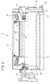
- the structure of the electric motor is shown in detail in FIG. 2.
- the electric motor has a rotor or rotor 32 and a stator or stator 34, the stator 34 is formed from individual windings with corresponding winding heads 36.
- the rotor 32 forms part of the propeller shaft 20 and is directly connected to it by a flange 44.
- the outside of the rotor 32 is pasted with permanent magnets 38, which are additionally bandaged.
- An air gap 40 is provided between the permanent magnets 38 and the stator 34.
- a housing 42 encloses the structure.
- the direct connection of the electric motor 24 to the rear axle differential 14 is provided, so that the electric motor has a first output via the cardan shaft to the front wheels and a second output via the rear axle differential to the rear wheels . Permanent four-wheel drive is thus achieved.
- the motor By designing the motor as a permanent magnet synchronous motor, a speed of rotation of the rotor 32 of up to 10,000 revolutions per minute is possible, so that a constant running of the motor 24 is possible even in high-speed vehicles without the motor being damaged.
- the housing 24 is approximately square in the outer shape of its radial cross section, so that the housing jacket has a relatively large amount of material in the corners of the square.
- a bore 50 is provided from the end face, which points in the direction of the differential, which begins at the end face of the pot-like housing 24 and extends through the wall almost to the bottom, which points in the direction of the internal combustion engine.
- two bores 52 and 54 are provided, which extend almost to the end face.
- the bores 50, 52 and 54 overlap so that an overall channel is formed in the inner region through which fluid can flow and which has a relatively large surface area due to the juxtaposition of the bores 50, 52 and 54.
- this wide channel which is composed of 50, 52 and 54, takes place solely through the circular bore 50, so that a connection of hoses or the like and the sealing is relatively simple.
- a connector 56 with a circular cross section is provided.
- the holes 52 and 54 made from behind form only two circular holes in the bottom, one of which is indicated at 58, and could accordingly be closed with simple circular plugs.
- a further bore 60 is provided through the bottom, via this bore 60, of which several can be attached in the same way, are in the quadrilaterals of the housing which is square in external cross section lying bores connected to each other, so that a circulation of cooling fluid can occur.
- the cover 62 to be placed on the end face after installation of the motor on the housing 24 has openings 56 in the area of the connection piece, so that these connection pieces pass through the cover 62 and no longer have to be interrupted and no sealing points between the cover and the housing are necessary.
- the end windings 36 are also arranged near the housing wall 42 and cast thermally conductively with this housing wall, so that the end windings, as particularly vulnerable points, are thermally cooled and are protected against overheating.
- air cooling can also be provided, with a closed cooling air circuit preferably being formed, which is therefore sucked out of air blown into the interior through the housing wall at a suitable point and passed in a closed circuit through a heat exchanger.
- a closed cooling air circuit preferably being formed, which is therefore sucked out of air blown into the interior through the housing wall at a suitable point and passed in a closed circuit through a heat exchanger.
Landscapes
- Engineering & Computer Science (AREA)
- Power Engineering (AREA)
- Transportation (AREA)
- Mechanical Engineering (AREA)
- Chemical & Material Sciences (AREA)
- Combustion & Propulsion (AREA)
- Sustainable Energy (AREA)
- Sustainable Development (AREA)
- Life Sciences & Earth Sciences (AREA)
- Motor Or Generator Cooling System (AREA)
- Electric Propulsion And Braking For Vehicles (AREA)
- Air-Conditioning For Vehicles (AREA)
- Reciprocating, Oscillating Or Vibrating Motors (AREA)
- Hybrid Electric Vehicles (AREA)
- Arrangement Or Mounting Of Propulsion Units For Vehicles (AREA)
- Permanent Field Magnets Of Synchronous Machinery (AREA)
- Permanent Magnet Type Synchronous Machine (AREA)
Claims (7)
- Véhicule (10) à propulsion électrique comportant un moteur électrique (24) qui comprend un rotor (32) de forme cylindrique au à section polygonale qui comporte des aimants permanents (38) placés sur le corps cylindrique ou polygonal du rotor, ainsi qu'un stator (34) conformé de manière correspondante et muni d'enroulements, le moteur électrique (24) étant placé dans un carter (42) muni de canaux (50, 52, 54) de circulation d'eau, caractérisé en ce que le moteur électrique est un moteur synchrone (24) à aimants permanents, en ce que le carter est en forme de pot et comporte un couvercle (62), le couvercle (62) présentant, dans la zone de sa surface d'appui sur la face frontale des parois latérales, des ouvertures à travers lesquelles les raccords (56) pour les canaux (50, 52, 54) de circulation d'eau sont introduits.
- Véhicule à propulsion électrique selon la revendication 1, caractérisé en ce que les raccords pour les canaux (50, 52, 54) de circulation d'eau sont en forme de manchons cylindriques (56).
- Véhicule à propulsion électrique selon l'une quelconque des revendications 1 et 2, caractérisé en ce que les têtes (36) des enroulements sont associées a la paroi (42) du carter par conduction thermique.
- Véhicule à propulsion électrique selon l'une quelconque des revendications 1 a 3, caractérisé en ce que les canaux sont réalisés sous la forme d'au moins un perçage (50) allant de la face frontale jusque juste avant la face de fond et d'au moins un perçage (52, 54) allant de la face de fond jusque juste avant la face frontale, les perçages venant de la face frontale et venant de la face de fond étant en chevauchement.
- Véhicule à propulsion électrique selon l'une quelconque des revendications 1 à 4, caractérisé en ce qu'il est prévu en outre un refroidissement à air au moyen d'une circulation d'air à l'intérieur du carter, un circuit fermé de circulation d'air étant formé et traversant un échangeur de chaleur après la traversée de l'intérieur du carter.
- Véhicule à propulsion électrique selon l'une quelconque des revendications 1 à 5, caractérisé en ce que l'électronique de puissance est également refroidie par eau.
- Véhicule a propulsion électrique selon la revendication 6, caractérisé en ce que les canaux de refroidissement dans lesquels circule l'eau pour le refroidissement du carter du moteur électrique et pour le refroidissement de l'électronique de puissance sont disposés en série.
Applications Claiming Priority (3)
| Application Number | Priority Date | Filing Date | Title |
|---|---|---|---|
| DE4115303 | 1991-05-10 | ||
| DE4115303 | 1991-05-10 | ||
| PCT/EP1992/000915 WO1992020545A1 (fr) | 1991-05-10 | 1992-04-27 | Vehicule propulse par un moteur electrique |
Publications (2)
| Publication Number | Publication Date |
|---|---|
| EP0583301A1 EP0583301A1 (fr) | 1994-02-23 |
| EP0583301B1 true EP0583301B1 (fr) | 1994-12-07 |
Family
ID=6431401
Family Applications (1)
| Application Number | Title | Priority Date | Filing Date |
|---|---|---|---|
| EP92909462A Expired - Lifetime EP0583301B1 (fr) | 1991-05-10 | 1992-04-27 | Vehicule propulse par un moteur electrique |
Country Status (5)
| Country | Link |
|---|---|
| EP (1) | EP0583301B1 (fr) |
| JP (1) | JPH07505755A (fr) |
| AT (1) | ATE115068T1 (fr) |
| DE (2) | DE4213132A1 (fr) |
| WO (1) | WO1992020545A1 (fr) |
Cited By (2)
| Publication number | Priority date | Publication date | Assignee | Title |
|---|---|---|---|---|
| US11502349B2 (en) | 2020-08-31 | 2022-11-15 | Borgwarner, Inc. | Cooling manifold assembly |
| US11837943B2 (en) | 2019-12-20 | 2023-12-05 | Volvo Car Corporation | Rotor air cooling system |
Families Citing this family (25)
| Publication number | Priority date | Publication date | Assignee | Title |
|---|---|---|---|---|
| DE4334134B4 (de) * | 1993-10-07 | 2005-09-29 | Battenfeld Kunststoffmaschinen Ges.M.B.H. | Verwendung einer Leistungs- und Ansteuerelektronik an einer Spritzgießmaschine |
| DE4407714C1 (de) * | 1994-03-08 | 1995-07-06 | Gruendl & Hoffmann | Elektromotor |
| DE4407713C1 (de) * | 1994-03-08 | 1995-04-13 | Gruendl & Hoffmann | Bürstenloser Elektromotor und Verfahren zu dessen Betrieb |
| DE19532135A1 (de) | 1995-08-31 | 1997-03-06 | Clouth Gummiwerke Ag | Antriebssystem, insbesondere für ein Kraftfahrzeug, und Verfahren zum Betreiben desselben |
| DE19532164A1 (de) | 1995-08-31 | 1997-03-06 | Clouth Gummiwerke Ag | Antriebssystem, insbesondere für ein Kraftfahrzeug, und Verfahren zum Betreiben desselben |
| US6158405A (en) * | 1995-08-31 | 2000-12-12 | Isad Electronic Systems | System for actively reducing rotational nonuniformity of a shaft, in particular, the drive shaft of an internal combustion engine, and method of operating the system |
| DE19532136A1 (de) * | 1995-08-31 | 1997-03-06 | Clouth Gummiwerke Ag | Antriebssystem, insbesondere für ein Kraftfahrzeug, und Verfahren zum Betreiben desselben |
| DE19532129A1 (de) | 1995-08-31 | 1997-03-06 | Clouth Gummiwerke Ag | System zur aktiven Verringerung von Drehungleichförmigkeiten einer Welle, insbesondere der Triebwelle eines Verbrennungsmotors, und Verfahren hierzu |
| JP2002515962A (ja) * | 1995-08-31 | 2002-05-28 | イーエスアーデー・エレクトロニク・ジステームス・ゲーエムベーハー・ウント・コンパニ・カーゲー | 回転する軸の半径方向振動を積極的に減少するための機構並びにこのために適する方法 |
| US6177734B1 (en) | 1998-02-27 | 2001-01-23 | Isad Electronic Systems Gmbh & Co. Kg | Starter/generator for an internal combustion engine, especially an engine of a motor vehicle |
| US6148784A (en) * | 1995-08-31 | 2000-11-21 | Isad Electronic Systems Gmbh & Co. Kg | Drive systems, especially for a motor vehicle, and method of operating same |
| JP2002516055A (ja) | 1995-08-31 | 2002-05-28 | イーエスアーデー・エレクトロニク・ジステームス・ゲーエムベーハー・ウント・コンパニ・カーゲー | 電気機械を用いて自動車用のけん引制御システムおよび方法 |
| DE19627323A1 (de) * | 1996-06-26 | 1998-01-02 | Siemens Ag | Gondelartig anzuordnender Schiffsantrieb mit Synchronmotor |
| DE19651119A1 (de) * | 1996-12-09 | 1998-07-16 | Magnet Motor Gmbh | Elektrische Maschine mit integriertem Wärmetauscher |
| ATE209587T1 (de) | 1997-06-12 | 2001-12-15 | Helmut Schiller | Triebsatzschwinge für ein- oder mehrspurige, elektromotorisch angetriebene fahrzeuge |
| DE29722432U1 (de) * | 1997-12-18 | 1998-02-26 | Siemens AG, 80333 München | Elektromotor |
| DE19902837C1 (de) | 1999-01-20 | 2000-08-10 | Siemens Ag | Rotierende elektrische Maschine mit permanenterregtem Rotor |
| DE10047911A1 (de) * | 2000-09-27 | 2002-04-18 | Siemens Ag | Antrieb eines Radsatzes |
| DE10122425B4 (de) * | 2001-05-09 | 2006-06-01 | Siemens Ag | Elektrische Maschine |
| DE20216112U1 (de) * | 2002-10-18 | 2004-03-18 | Baumüller Nürnberg GmbH | Kühl-Gehäusemantel für elektrische Maschinen |
| JP4146784B2 (ja) * | 2003-11-18 | 2008-09-10 | 富士重工業株式会社 | ハイブリッド車両の駆動力制御装置 |
| US7950481B2 (en) * | 2005-09-29 | 2011-05-31 | Caterpillar Inc. | Electric powertrain for machine |
| EP2112744A1 (fr) * | 2008-04-24 | 2009-10-28 | Magneti Marelli Holding S.p.A. | Machine synchrone polyphasée pour convertir l'énergie cinétique en énergie électrique et l'énergie électrique en une énergie cinétique à bord d'un véhicule de transport, et véhicule de transport comprenant cette machine électrique |
| DE102010054496B4 (de) | 2010-12-14 | 2020-06-18 | Volkswagen Ag | Durch Gießen hergestelltes Elektromotorgehäuseteil für einen Elektromotor |
| CN107947475A (zh) * | 2017-11-30 | 2018-04-20 | 广东葆德科技有限公司 | 一种散热性电机 |
Family Cites Families (3)
| Publication number | Priority date | Publication date | Assignee | Title |
|---|---|---|---|---|
| GB803388A (en) * | 1955-10-15 | 1958-10-22 | Bbc Brown Boveri & Cie | Improvements in or relating to cooling systems |
| US2938131A (en) * | 1957-07-15 | 1960-05-24 | Smith Corp A O | Liquid filled submersible motor |
| JP2567014B2 (ja) * | 1988-02-02 | 1996-12-25 | ファナック株式会社 | 液冷モータの冷却用管路接合構造 |
-
1992
- 1992-04-21 DE DE4213132A patent/DE4213132A1/de not_active Withdrawn
- 1992-04-27 EP EP92909462A patent/EP0583301B1/fr not_active Expired - Lifetime
- 1992-04-27 WO PCT/EP1992/000915 patent/WO1992020545A1/fr not_active Ceased
- 1992-04-27 JP JP4508508A patent/JPH07505755A/ja active Pending
- 1992-04-27 DE DE59200923T patent/DE59200923D1/de not_active Expired - Fee Related
- 1992-04-27 AT AT92909462T patent/ATE115068T1/de not_active IP Right Cessation
Cited By (2)
| Publication number | Priority date | Publication date | Assignee | Title |
|---|---|---|---|---|
| US11837943B2 (en) | 2019-12-20 | 2023-12-05 | Volvo Car Corporation | Rotor air cooling system |
| US11502349B2 (en) | 2020-08-31 | 2022-11-15 | Borgwarner, Inc. | Cooling manifold assembly |
Also Published As
| Publication number | Publication date |
|---|---|
| DE4213132A1 (de) | 1992-11-12 |
| ATE115068T1 (de) | 1994-12-15 |
| DE59200923D1 (de) | 1995-01-19 |
| JPH07505755A (ja) | 1995-06-22 |
| WO1992020545A1 (fr) | 1992-11-26 |
| EP0583301A1 (fr) | 1994-02-23 |
Similar Documents
| Publication | Publication Date | Title |
|---|---|---|
| DE4213132A1 (de) | Elektrisch antreibbares kraftfahrzeug | |
| DE69827376T2 (de) | Kompaktantrieb | |
| EP0685122B1 (fr) | Machine electrique comportant au moins un embrayage | |
| DE102004054601B4 (de) | Kompaktantrieb, Spiroplangetriebe und Verfahren zur Fertigung eines Antriebs | |
| DE60035592T2 (de) | Elektrische maschine | |
| DE3883563T2 (de) | Mehrfach magnetisch angetriebene Pumpe. | |
| DE4121430C1 (fr) | ||
| EP0778649B1 (fr) | Ensemble moto-pompe | |
| DE69005567T2 (de) | Foucault-Strom-Verzögerungssystem. | |
| EP0919512B1 (fr) | Treuil avec électromoteur refroidi par un liquide | |
| AT414064B (de) | Pumpe für flüssige medien | |
| EP3766164B1 (fr) | Véhicule électrique | |
| DE69501066T3 (de) | Synchronmotor mit im Rotor eingebetteten Permanentmagneten | |
| EP1173917A1 (fr) | Unite de production de courant constituee d'un generateur et d'un moteur a combustion interne a piston alternatif servant de systeme de commande | |
| EP0660492B1 (fr) | Système de refroidissement d'un moteur | |
| DE112008002978T5 (de) | Elektromotor und Antriebsvorrichtung | |
| EP3777478B1 (fr) | Générateur de chaleur à induction par rotation avec excitation dc, efficacité électrique / cinétique extrêmement faible et un coefficient de performance thermique extrêmement élevé | |
| DE3732799C2 (fr) | ||
| DE2307800A1 (de) | Kollektorloser gleichstrommotor fuer hohe drehzahlen | |
| EP0585644B1 (fr) | Machine électrique entièrement fermée, refroidie en surface par liquide | |
| DE19736907A1 (de) | Elektrisch angetriebener Verdichter | |
| EP1081386A2 (fr) | Moteur électrique a flux axial | |
| DE102004003400B4 (de) | Kreiselpumpenaggregat | |
| EP0788779B1 (fr) | Moteur à courant continu pour l'entraínement d'un instrument dentaire | |
| EP1516109B1 (fr) | Dispositif de refroidissement d'unite generatrice de courant |
Legal Events
| Date | Code | Title | Description |
|---|---|---|---|
| PUAI | Public reference made under article 153(3) epc to a published international application that has entered the european phase |
Free format text: ORIGINAL CODE: 0009012 |
|
| 17P | Request for examination filed |
Effective date: 19930625 |
|
| AK | Designated contracting states |
Kind code of ref document: A1 Designated state(s): AT DE FR GB |
|
| 17Q | First examination report despatched |
Effective date: 19940325 |
|
| GRAA | (expected) grant |
Free format text: ORIGINAL CODE: 0009210 |
|
| AK | Designated contracting states |
Kind code of ref document: B1 Designated state(s): AT DE FR GB |
|
| REF | Corresponds to: |
Ref document number: 115068 Country of ref document: AT Date of ref document: 19941215 Kind code of ref document: T |
|
| REF | Corresponds to: |
Ref document number: 59200923 Country of ref document: DE Date of ref document: 19950119 |
|
| ET | Fr: translation filed | ||
| GBT | Gb: translation of ep patent filed (gb section 77(6)(a)/1977) |
Effective date: 19950130 |
|
| PLBE | No opposition filed within time limit |
Free format text: ORIGINAL CODE: 0009261 |
|
| 26N | No opposition filed | ||
| PGFP | Annual fee paid to national office [announced via postgrant information from national office to epo] |
Ref country code: DE Payment date: 19990409 Year of fee payment: 8 |
|
| PGFP | Annual fee paid to national office [announced via postgrant information from national office to epo] |
Ref country code: FR Payment date: 19990419 Year of fee payment: 8 |
|
| PGFP | Annual fee paid to national office [announced via postgrant information from national office to epo] |
Ref country code: AT Payment date: 19990426 Year of fee payment: 8 |
|
| PGFP | Annual fee paid to national office [announced via postgrant information from national office to epo] |
Ref country code: GB Payment date: 20000323 Year of fee payment: 9 |
|
| PG25 | Lapsed in a contracting state [announced via postgrant information from national office to epo] |
Ref country code: AT Free format text: LAPSE BECAUSE OF NON-PAYMENT OF DUE FEES Effective date: 20000427 |
|
| PG25 | Lapsed in a contracting state [announced via postgrant information from national office to epo] |
Ref country code: FR Free format text: LAPSE BECAUSE OF NON-PAYMENT OF DUE FEES Effective date: 20001229 |
|
| PG25 | Lapsed in a contracting state [announced via postgrant information from national office to epo] |
Ref country code: DE Free format text: LAPSE BECAUSE OF NON-PAYMENT OF DUE FEES Effective date: 20010201 |
|
| REG | Reference to a national code |
Ref country code: FR Ref legal event code: ST |
|
| PG25 | Lapsed in a contracting state [announced via postgrant information from national office to epo] |
Ref country code: GB Free format text: LAPSE BECAUSE OF NON-PAYMENT OF DUE FEES Effective date: 20010427 |
|
| GBPC | Gb: european patent ceased through non-payment of renewal fee |
Effective date: 20010427 |