EP0583476A1 - Procede de commande adaptative en mode reglable pour objet commande comprenant un systeme elastique - Google Patents
Procede de commande adaptative en mode reglable pour objet commande comprenant un systeme elastique Download PDFInfo
- Publication number
- EP0583476A1 EP0583476A1 EP93901526A EP93901526A EP0583476A1 EP 0583476 A1 EP0583476 A1 EP 0583476A1 EP 93901526 A EP93901526 A EP 93901526A EP 93901526 A EP93901526 A EP 93901526A EP 0583476 A1 EP0583476 A1 EP 0583476A1
- Authority
- EP
- European Patent Office
- Prior art keywords
- processing
- value
- servomotor
- suf
- estimated
- Prior art date
- Legal status (The legal status is an assumption and is not a legal conclusion. Google has not performed a legal analysis and makes no representation as to the accuracy of the status listed.)
- Withdrawn
Links
Images



Classifications
-
- G—PHYSICS
- G05—CONTROLLING; REGULATING
- G05B—CONTROL OR REGULATING SYSTEMS IN GENERAL; FUNCTIONAL ELEMENTS OF SUCH SYSTEMS; MONITORING OR TESTING ARRANGEMENTS FOR SUCH SYSTEMS OR ELEMENTS
- G05B19/00—Program-control systems
- G05B19/02—Program-control systems electric
- G05B19/18—Numerical control [NC], i.e. automatically operating machines, in particular machine tools, e.g. in a manufacturing environment, so as to execute positioning, movement or co-ordinated operations by means of program data in numerical form
- G05B19/19—Numerical control [NC], i.e. automatically operating machines, in particular machine tools, e.g. in a manufacturing environment, so as to execute positioning, movement or co-ordinated operations by means of program data in numerical form characterised by positioning or contouring control systems, e.g. to control position from one programmed point to another or to control movement along a programmed continuous path
-
- G—PHYSICS
- G05—CONTROLLING; REGULATING
- G05B—CONTROL OR REGULATING SYSTEMS IN GENERAL; FUNCTIONAL ELEMENTS OF SUCH SYSTEMS; MONITORING OR TESTING ARRANGEMENTS FOR SUCH SYSTEMS OR ELEMENTS
- G05B2219/00—Program-control systems
- G05B2219/30—Nc systems
- G05B2219/41—Servomotor, servo controller till figures
- G05B2219/41112—Control parameter such as motor controlled by a torque signal
-
- G—PHYSICS
- G05—CONTROLLING; REGULATING
- G05B—CONTROL OR REGULATING SYSTEMS IN GENERAL; FUNCTIONAL ELEMENTS OF SUCH SYSTEMS; MONITORING OR TESTING ARRANGEMENTS FOR SUCH SYSTEMS OR ELEMENTS
- G05B2219/00—Program-control systems
- G05B2219/30—Nc systems
- G05B2219/41—Servomotor, servo controller till figures
- G05B2219/41251—Servo with spring, resilient, elastic element, twist
-
- G—PHYSICS
- G05—CONTROLLING; REGULATING
- G05B—CONTROL OR REGULATING SYSTEMS IN GENERAL; FUNCTIONAL ELEMENTS OF SUCH SYSTEMS; MONITORING OR TESTING ARRANGEMENTS FOR SUCH SYSTEMS OR ELEMENTS
- G05B2219/00—Program-control systems
- G05B2219/30—Nc systems
- G05B2219/41—Servomotor, servo controller till figures
- G05B2219/41367—Estimator, state observer, space state controller
-
- G—PHYSICS
- G05—CONTROLLING; REGULATING
- G05B—CONTROL OR REGULATING SYSTEMS IN GENERAL; FUNCTIONAL ELEMENTS OF SUCH SYSTEMS; MONITORING OR TESTING ARRANGEMENTS FOR SUCH SYSTEMS OR ELEMENTS
- G05B2219/00—Program-control systems
- G05B2219/30—Nc systems
- G05B2219/42—Servomotor, servo controller kind till VSS
- G05B2219/42352—Sliding mode controller SMC, select other gain
Definitions
- the present invention relates to a control method for object of control including spring system, such as a robot driven by a servomotor, more particularly to an adaptive sliding mode control method for object of control.
- linear control such as PI (proportional-plus-integral) control
- PI proportional-plus-integral
- a robot since a robot is generally constructed in the form of a cantilever, it undergoes a large variation of inertia depending on the attitude of the robot, accompanying the change in the response of a servo system. Moreover, a robot has a low rigidity and resulting low resonance frequency due to the effects of the spring element such as the speed reducer and others, and so, in positioning the distal end (tool center point) of a robot, the end of the robot tends to sway even after positioning by servomotor.
- the present inventors have proposed inventions in which sliding mode control is applied to a control object driven by a servomotor, in order to prevent a moving part of a machine from vibrating (See Publication JP-A-3-92911 and JP-A-3-118618).
- the object of the present invention is to provide an adaptive sliding mode control method capable of improving the convergence of the aforesaid estimated parameters, as well as capable of providing an excellent vibration-damping effect.
- an adaptive sliding mode control method is arranged so that the difference between the position of a servomotor and the position of a moving part of an object of control driven by the servomotor is fed back to a phase plane for sliding mode control, and a torque command for the servomotor is controlled so that the value of the phase plane converges to 0.
- the difference ⁇ t between the position of the servomotor and the position of the moving part of the object of control driven by the servomotor and the differential ⁇ t thereof are obtained by observer processing.
- adaptive sliding mode control comprising the following processings is applied to a robot which is regarded as an object of control including a spring system. That is, the control comprises: setting and entering, in a memory of a servo circuit, various constants required for a sliding mode control processing and observer processing, besides the maximum value Dis(max) and minimum value Dis(min) of a foreseen disturbance; starting the operation of the robot, reading a position command ⁇ r and a position feedback amount ⁇ with every period, and calculating a motor speed ⁇ , a command speed ⁇ r, a command acceleration r, a position deviation ⁇ equivalent to the difference between the position command ⁇ r and the position feedback amount ⁇ , and a speed deviation ⁇ on the bases of the read values; executing observer processing in accordance with the obtained motor speed ⁇ to obtain an estimated torsion ⁇ tf and an estimated torsional speed ⁇ tf between a motor and the distal end of the robot, further subjecting these deviations to filter
- the difference between the position of the servomotor and the position of the moving part of the object of control driven by the servomotor is fed back to the phase plane for sliding mode control; the torque command for the motor is calculated so that the value of the phase plane converges to 0; and the servomotor is driven in accordance with this torque command.
- the vibration of the moving part of the object of control after positioning is reduced.
- a torsion ⁇ t (more specifically, a value obtained by multiplying an estimated position deviation by a transfer function (S + Kp)/(S + A) , as will be mentioned later) is fed back to a phase plane Suf for sliding mode control.
- This phase plane is given by the following equation (1).
- the following equation (2) is an equation for the motion of an object of control such as the robot.
- ⁇ is a position deviation equivalent to the difference between a command position of the motor and the actual position of the motor, and ⁇ is the actual position of the motor.
- Kp is a position loop gain
- K1 is a feedback gain of the torsion ⁇ t of the machine or control object, which is a state quantity
- ⁇ is a torque
- J is inertia
- A is a coefficient of dynamic friction
- Gr is a gravity term
- Dis is a disturbance.
- the torque command ⁇ for the motor is given by the following equation.
- K2 is a constant determined depending on the maximum value of the inertia in the manner mentioned later;
- Jhat is an estimated value of the inertia term;
- Ahat is an estimated value of the coefficient of dynamic friction;
- Grhat is an estimated value of the gravity term; and
- ⁇ 1 is a switching input.
- a Liapunov function candidate V is given by the following equation.
- V (1/2)J ⁇ Suf2 + (1/2) ⁇ ⁇ Jbar2 + (1/2) ⁇ ⁇ Abar2 + (1/2) ⁇ ⁇ Grbar2, (5)
- ⁇ , ⁇ and ⁇ are positive adjustment parameters for determining an adaptive speed
- Jbar, Abar and Grbar are estimated errors of the inertia term
- coefficient of dynamic friction, and gravity term respectively, having relationships given by the following equations (6):
- the aforesaid Liapunov function candidate V is a function having a minimum value of 0 and being always positive.
- Equation (11) in order to make the first term of the right side of equation (11) negative, it is sufficient that J ⁇ Kp - K2 ⁇ 0 be established.
- the torque command ⁇ for the motor can be obtained from equation (4) by adjusting the value (equation (12)) of the factor K2 to Kp ⁇ J(max) and adjusting the switching input ⁇ 1 to Dis(max) or Dis(max) depending on whether the sign of Suf is plus or minus.
- Fig. 2 shows a model of the robot. The observer will be considered with reference to this model.
- numerals 10 and 11 designate the motor and machine sides, respectively.
- a speed reducer is provided between these sides, and its spring constant and viscosity term are represented by Kc and Bk, respectively.
- Kc and Bk spring constant and viscosity term
- an equation of motion for the motor side 10 is given by Further, an equation of motion for the load side (machine side) 11 is given by
- ( ⁇ - ⁇ t) represents a position deviation (torsion) of the load compared with the rotational position of the rotor of the motor, while ( ⁇ - ⁇ t) represents a speed deviation (torsional speed).
- ⁇ t and ⁇ t are obtained by subjecting ⁇ tf and ⁇ tf, obtained by the observer processing, to filtering processing using the transfer function (S + Kp)/(S + A).
- ⁇ t ⁇ tf ⁇ (S + Kp)/(S + A)
- ⁇ ⁇ t ⁇ ⁇ tf ⁇ (S + Kp)/(S + A).
- Fig. 1 is a block diagram showing the principal part of a robot control system for carrying out one embodiment of the present invention.
- numeral 1 denotes a host processor for controlling the robot.
- the host processor 1 not only performs interpolation, conversion or reverse conversion of coordinate values in a rectangular coordinate system into or from rotational angles of individual axes, etc., but distributes a position command to each axis of the robot.
- Numeral 2 denotes a common RAM which mediates between the host processor 1 and a processor of a digital servo circuit 3 in transferring information.
- the common RAM 2 delivers position commands and other data written by the host processor 1 to the processor of the digital servo circuit 3, and deliver alarm information and the like written by the processor of the digital servo circuit 3 to the host processor.
- Numeral 3 denotes the digital servo circuit 3, which is formed of a digital signal processor and the like including a processor, ROM, RAM, etc., and controls servomotors for the individual axes of the robot, thereby executing the sliding mode control processing and the observer processing according to the present invention.
- Numeral 4 denotes a servo amplifier formed of a transistor inverter or the like, and 5 denotes a servomotor.
- numeral 6 denotes a pulse coder for detecting the position ⁇ of the servomotor 5. The position ⁇ is fed back to the digital servo circuit. For each of the servo amplifier 4 and servomotor 5, only one axis is shown in the figure.
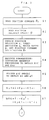
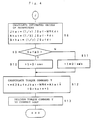
- Figs. 3 and 4 are flow charts relating to a servomotor control processing of the present invention to be executed by the processings of the digital servo circuit according to the present embodiment.
- This processor executes the processings shown in Figs. 3 and 4 in every predetermined period.
- the host processor 1 distributes the position commands to the individual axes, while the processor of the digital servo circuit 3 reads the position command ⁇ r from the common RAM 2, and also reads a position feedback amount ⁇ delivered from the pulse coder 6 (Steps S1 and S2). Then, the position deviation ⁇ is obtained in accordance with the position command ⁇ r and the position feedback amount ⁇ . More specifically, the position deviation ⁇ is obtained by adding a value, obtained by subtracting the position feedback position ⁇ from the position command ⁇ r, to a register in which the position deviation is stored. Further, the motor speed (first-order differential of motor position ⁇ ) ⁇ is obtained by subtracting the feedback position detected in the preceding period from the detected feedback position ⁇ .
- the speed deviation ⁇ is obtained by subtracting the aforesaid motor speed from the command speed ⁇ r (first-order differential of position command ⁇ r) equivalent to a value obtained by subtracting the position command for the preceding period from the position command ⁇ r
- the command acceleration (second-order differential of position command ⁇ r) r is obtained by subtracting the command speed obtained in the preceding period from the obtained command speed ⁇ r (Step S3).
- Step S4 the aforesaid observer processing is executed on the basis of the motor speed ⁇ , whereby the estimated torsion ⁇ tf and the estimated torsional speed ⁇ tf between the motor and the distal end of the robot are obtained (Step S4).
- computations are made according to equations (32) and (33) to effect filtering processing, whereby a filtered estimated torsion ⁇ t and a filtered estimated torsional speed ⁇ t between the motor and the distal end of the robot are obtained (Step S5).
- the computation by equation (1) is made in accordance with the position deviation ⁇ and the speed deviation ⁇ , which are obtained in Step S3, and the filtered estimated torsion ⁇ t between the motor and the distal end of the robot obtained in Step S5, whereby the phase plane Suf is obtained (Step S6).
- a value relating to the estimated value Jhat of the inertia of equation (4) is obtained in accordance with the position deviation ⁇ and the position command acceleration r, which are obtained in Step S3, and the estimated torsion ⁇ t and the estimated torsional speed ⁇ t, which are obtained in Step S5, and this value is stored as WRK in the register (Step S7).
- equations (15), (16) and (17) are integrated in accordance with the respective values of the phase plane Suf and WRK respectively obtained in Steps S6 and S7, whereby the estimated value Jhat of the inertia term, the estimated value Ahat of the coefficient of dynamic friction, and the estimated value Grhat of the gravity term are obtained.
- value of Suf ⁇ WRK is calculated at every period, and the calculated values are integrated in an accumulator, whereby the estimated value Jhat of the inertia term is obtained by multiplying the integrated value by a factor (1/ ⁇ ).
- value of suf ⁇ ⁇ is obtained and integrated in an accumulator to estimate Ahat, the value of coefficient of dynamic friction by multiplying the integrated value by a factor (1/ ⁇ ).
- the estimated value Grhat of the gravity term is obtained by multiplying the value of Suf, which is integrated in the accumulator, by a factor (1/ ⁇ ).
- Step S9 it is determined whether or not the value of the phase plane Suf is smaller than 0 (Step S9). If not smaller than 0, Dis(max) is stored in the register as the switching input ⁇ 1, and if negative, Dis(min) is stored (Steps S10 and S11).
- the torque command ⁇ for the motor is obtained by making the computation by equation (4) (Step S12), and computed torque command ⁇ is delivered to a current loop (Step S13), whereupon the processing for the processing period concerned is finished.
- the processor of the digital servo circuit 3 executes the aforesaid processing for each period, thereby controlling the servomotor to drive the robot.
- Figs. 5 to 8 are diagrams showing simulation data used to observe the effects of the present invention.
- Fig. 5 is a diagram showing the frequency response of a model spring system.
- Fig. 6 shows input waveforms for a simulation, in which (a), (b), (c) and (d) illustrate the jerk, acceleration, speed, and position, respectively.
- Fig. 7 shows data indicative of simulation results obtained when the present invention is not applied, while Fig. 8 shows data indicative of simulation results obtained when the present invention is applied.
- (a) illustrates the motor position ⁇ ; (b), motor speed ⁇ (1); (c), arm distal end position ⁇ t; (d), arm distal end position speed ⁇ t; (e), estimated value Jhat of the inertia; (f), estimated value Ahat of the coefficient of dynamic friction; (g), estimated value Grhat of the gravity term; and (h), torque command ⁇ for the motor.
- the difference between the position of the motor and the distal end position of the moving part driven by the motor can be fed back to the phase plane for sliding mode to improve the convergence of the parameters (inertia, coefficient of dynamic friction, and gravity term) of the object of control, so that vibration of the machine moving part can be reduced.
Landscapes
- Engineering & Computer Science (AREA)
- Human Computer Interaction (AREA)
- Manufacturing & Machinery (AREA)
- Physics & Mathematics (AREA)
- General Physics & Mathematics (AREA)
- Automation & Control Theory (AREA)
- Control Of Position Or Direction (AREA)
- Feedback Control In General (AREA)
- Control Of Electric Motors In General (AREA)
Abstract
Procédé de commande adaptative en mode réglable permettant d'améliorer la convergence des paramètres d'évaluation et présentant d'excellentes caractéristiques d'amortissement. On détermine (S3) une erreur de position epsilon entre une position d'instruction et une position de moteur, une erreur de vitesse epsilon, et une accélération r de la position d'instruction. On détermine (S4, S5) une erreur de position epsilont entre la position de moteur et une partie mobile mécanique, ainsi que sa valeur de différentiation epsilont. On obtient (S7) un plan de phase Suf en réinjectant l'erreur de position epsilont entre la position de moteur et la partie mobile mécanique. On détermine (S8) les valeurs d'évaluation Jhat, Ahat et Grhat des termes de l'inertie, du coefficient de friction cinétique, et de la pesanteur, et on adapte un signal d'entrée de commutateur tau1 à une valeur maximale Dis(max) ou minimale Dis(min) de perturbation en fonction du signe du plan de phase Suf (S10, S11). On détermine l'instruction de couple tau destinée au moteur, et on l'introduit dans une boucle de courant (S12, S13). On réduit les vibrations de la partie mobile mécanique une fois que le positionnement est achevé.
Applications Claiming Priority (2)
| Application Number | Priority Date | Filing Date | Title |
|---|---|---|---|
| JP4056344A JPH05216504A (ja) | 1992-02-06 | 1992-02-06 | バネ系を含む制御対象に対する適応的スライディングモード制御方式 |
| JP56344/92 | 1992-02-06 |
Publications (2)
| Publication Number | Publication Date |
|---|---|
| EP0583476A1 true EP0583476A1 (fr) | 1994-02-23 |
| EP0583476A4 EP0583476A4 (en) | 1996-02-07 |
Family
ID=13024619
Family Applications (1)
| Application Number | Title | Priority Date | Filing Date |
|---|---|---|---|
| EP93901526A Withdrawn EP0583476A4 (en) | 1992-02-06 | 1993-01-18 | Adaptive sliding mode control method for control object including spring system |
Country Status (4)
| Country | Link |
|---|---|
| US (1) | US5442270A (fr) |
| EP (1) | EP0583476A4 (fr) |
| JP (1) | JPH05216504A (fr) |
| WO (1) | WO1993016423A1 (fr) |
Cited By (8)
| Publication number | Priority date | Publication date | Assignee | Title |
|---|---|---|---|---|
| DE10054534A1 (de) * | 1999-11-19 | 2001-07-26 | Unisia Jecs Corp | Gleitmodusregelungseinheit für eine elektronisch geregelte Drosselvorrichtung |
| EP1118436A4 (fr) * | 1999-04-05 | 2006-05-31 | Sony Corp | Robot, circuit asservi, actionneur, procede de commande d'un robot, et procede de commande d'un actionneur |
| CN103257573A (zh) * | 2013-05-23 | 2013-08-21 | 西北工业大学 | 一种用于飞机电刹车双余度无刷直流电机的滑模控制方法 |
| CN105173606A (zh) * | 2015-07-27 | 2015-12-23 | 江苏大学 | 混联式汽车电泳涂装输送机构的复合动力学控制系统与方法 |
| CN106774385A (zh) * | 2016-12-05 | 2017-05-31 | 烟台南山学院 | 一种采用自适应变结构的飞艇定点悬停控制方法 |
| CN108459499A (zh) * | 2018-02-27 | 2018-08-28 | 北京控制工程研究所 | 一种抑制液体晃动时间最优避障方法及系统 |
| CN110412870A (zh) * | 2019-07-04 | 2019-11-05 | 南京理工大学 | 基于扰动观测器与趋近自适应滑模的立式物料传送装置控制方法 |
| CN113703313A (zh) * | 2021-10-28 | 2021-11-26 | 季华实验室 | 一种基于改进预设性能的无模型自适应滑模约束控制方法 |
Families Citing this family (63)
| Publication number | Priority date | Publication date | Assignee | Title |
|---|---|---|---|---|
| US5532566A (en) * | 1995-02-01 | 1996-07-02 | Tektronix, Inc. | Voltage mode drive of servo system |
| JP3422393B2 (ja) * | 1995-02-24 | 2003-06-30 | 本田技研工業株式会社 | 内燃機関の空燃比制御装置 |
| US5781365A (en) * | 1995-03-07 | 1998-07-14 | Cirrus Logic, Inc. | Sliding mode control of a magnetoresistive read head for magnetic recording |
| US5847895A (en) * | 1995-03-07 | 1998-12-08 | Cirrus Logic, Inc. | Chatter reduction in sliding mode control of a disk drive actuator |
| US5825582A (en) * | 1995-03-07 | 1998-10-20 | Cirrus Logic, Inc. | Sliding mode control of a disk drive actuator for positioning a read/write head over a selected track during seeking and tracking operations |
| US5699207A (en) * | 1995-03-07 | 1997-12-16 | Cirrus Logic, Inc. | Chatter reduction in sliding mode control of a disk drive actuator |
| US5650704A (en) * | 1995-06-29 | 1997-07-22 | Massachusetts Institute Of Technology | Elastic actuator for precise force control |
| US5814850A (en) * | 1995-08-22 | 1998-09-29 | Nippon Steel Corporation | Semiconductor device including a capacitor responsible for a power supply voltage to semiconductor device and capable of blocking an increased voltage |
| US5982721A (en) * | 1996-03-29 | 1999-11-09 | Cirrus Logic, Inc. | Optical disc drive comprising switching gains for forcing phase states to follow a sliding line trajectory in a servo system |
| JP3239789B2 (ja) * | 1997-02-21 | 2001-12-17 | 松下電器産業株式会社 | 制御装置および制御方法 |
| KR100237306B1 (ko) * | 1997-03-25 | 2000-01-15 | 윤종용 | 2관성 공진계의 진동 억제방법 및 장치 |
| US6046878A (en) * | 1997-04-30 | 2000-04-04 | Seagate Technology, Inc. | Object positioning using discrete sliding mode control with variable parameters |
| KR19990032321A (ko) * | 1997-10-17 | 1999-05-15 | 이해규 | 교류전동기를 이용한 기계시스템 제어방법 |
| US6185467B1 (en) | 1998-09-02 | 2001-02-06 | Cirrus Logic, Inc. | Adaptive discrete-time sliding mode controller |
| US6798611B1 (en) | 1998-09-02 | 2004-09-28 | Cirrus Logic, Inc. | Disk storage system employing a discrete-time sliding mode controller for servo control |
| US6236895B1 (en) | 1998-09-02 | 2001-05-22 | Cirrus Logic, Inc. | Reference estimator in a discrete-time sliding mode controller |
| US6060854A (en) * | 1998-11-12 | 2000-05-09 | Vickers, Inc. | Method and apparatus for compensating for windup in a machine |
| US6699665B1 (en) * | 2000-11-08 | 2004-03-02 | Surface Logix, Inc. | Multiple array system for integrating bioarrays |
| US20030009240A1 (en) * | 2001-04-20 | 2003-01-09 | Honda Giken Kogyo Kabushiki Kaisha | Control system for plant |
| US6636783B2 (en) * | 2001-06-05 | 2003-10-21 | Honda Giken Kogyo Kabushiki Kaisha | Control system for throttle valve actuating device |
| US6958850B2 (en) * | 2002-03-12 | 2005-10-25 | Corning Incorporated | Pointing angle control of electrostatic micro mirrors with modified sliding mode control algorithm for precision control |
| US6985271B2 (en) * | 2002-03-12 | 2006-01-10 | Corning Incorporated | Pointing angle control of electrostatic micro mirrors |
| US20040064195A1 (en) | 2002-07-15 | 2004-04-01 | Hugh Herr | Variable-mechanical-impedance artificial legs |
| JP3739749B2 (ja) * | 2003-01-07 | 2006-01-25 | ファナック株式会社 | 制御装置 |
| JP2007515697A (ja) * | 2003-05-13 | 2007-06-14 | ナショナル ユニバーシティ オブ シンガポール | ダンパシステム |
| US7019482B2 (en) * | 2003-05-29 | 2006-03-28 | Sodick Co., Ltd. | Motion controller having sliding mode controller |
| JP4014162B2 (ja) * | 2003-08-06 | 2007-11-28 | ヤマザキマザック株式会社 | 工作機械の位置制御装置及び工作機械の位置制御方法 |
| US8075633B2 (en) | 2003-09-25 | 2011-12-13 | Massachusetts Institute Of Technology | Active ankle foot orthosis |
| US7190140B2 (en) * | 2004-04-05 | 2007-03-13 | Sodick Co., Ltd. | Sliding mode controller position control device |
| US20070162152A1 (en) | 2005-03-31 | 2007-07-12 | Massachusetts Institute Of Technology | Artificial joints using agonist-antagonist actuators |
| US10080672B2 (en) | 2005-03-31 | 2018-09-25 | Bionx Medical Technologies, Inc. | Hybrid terrain-adaptive lower-extremity systems |
| US20060249315A1 (en) | 2005-03-31 | 2006-11-09 | Massachusetts Institute Of Technology | Artificial human limbs and joints employing actuators, springs, and variable-damper elements |
| US10307272B2 (en) | 2005-03-31 | 2019-06-04 | Massachusetts Institute Of Technology | Method for using a model-based controller for a robotic leg |
| US8512415B2 (en) | 2005-03-31 | 2013-08-20 | Massachusetts Institute Of Technology | Powered ankle-foot prothesis |
| US20070043449A1 (en) | 2005-03-31 | 2007-02-22 | Massachusetts Institute Of Technology | Artificial ankle-foot system with spring, variable-damping, and series-elastic actuator components |
| US11278433B2 (en) | 2005-03-31 | 2022-03-22 | Massachusetts Institute Of Technology | Powered ankle-foot prosthesis |
| US8864846B2 (en) | 2005-03-31 | 2014-10-21 | Massachusetts Institute Of Technology | Model-based neuromechanical controller for a robotic leg |
| US20070123997A1 (en) | 2005-03-31 | 2007-05-31 | Massachusetts Institute Of Technology | Exoskeletons for running and walking |
| US8500823B2 (en) | 2005-03-31 | 2013-08-06 | Massachusetts Institute Of Technology | Powered artificial knee with agonist-antagonist actuation |
| US8209052B2 (en) * | 2006-03-31 | 2012-06-26 | Societe de Commercialisation de Produits de la Recherche Appliquee-Socpra-Sciences et Genie, S.E.C. | High performance differential actuator for robotic interaction tasks |
| EP3219295B1 (fr) | 2008-09-04 | 2023-11-15 | Otto Bock HealthCare LP | Systèmes hybrides à extrémités inférieures s'adaptant au terrain |
| US20110082566A1 (en) | 2008-09-04 | 2011-04-07 | Herr Hugh M | Implementing a stand-up sequence using a lower-extremity prosthesis or orthosis |
| JP5371494B2 (ja) * | 2009-03-09 | 2013-12-18 | 三菱重工業株式会社 | 直線移動装置 |
| WO2011126985A2 (fr) | 2010-04-05 | 2011-10-13 | Iwalk, Inc. | Commande du couple dans une prothèse ou une orthèse |
| JP5453606B2 (ja) * | 2010-04-09 | 2014-03-26 | 株式会社ハーモニック・ドライブ・システムズ | 波動歯車装置を備えたアクチュエータの位置決め制御方法 |
| WO2012096956A1 (fr) | 2011-01-10 | 2012-07-19 | Iwalk, Inc. | Orthèse d'articulation électrique |
| WO2012097156A2 (fr) | 2011-01-12 | 2012-07-19 | Iwalk, Inc. | Commande de dispositifs électriques d'augmentation humaine |
| US9687377B2 (en) | 2011-01-21 | 2017-06-27 | Bionx Medical Technologies, Inc. | Terrain adaptive powered joint orthosis |
| JP5370392B2 (ja) * | 2011-02-23 | 2013-12-18 | 株式会社安川電機 | ロボットシステム、ロボット制御装置およびロボット制御方法 |
| WO2012125562A1 (fr) | 2011-03-11 | 2012-09-20 | Iwalk, Inc. | Organes de commande de joint biomimétique |
| JP5209810B1 (ja) * | 2011-07-27 | 2013-06-12 | ファナック株式会社 | イナーシャと摩擦係数とばね定数を同時に推定する機能を備える電動機の制御装置 |
| WO2013067407A1 (fr) | 2011-11-02 | 2013-05-10 | Iwalk, Inc. | Prothèse transfémorale biomimétique |
| US9032635B2 (en) | 2011-12-15 | 2015-05-19 | Massachusetts Institute Of Technology | Physiological measurement device or wearable device interface simulator and method of use |
| US9221177B2 (en) | 2012-04-18 | 2015-12-29 | Massachusetts Institute Of Technology | Neuromuscular model-based sensing and control paradigm for a robotic leg |
| EP2858602A2 (fr) | 2012-06-12 | 2015-04-15 | Iwalk, Inc. | Dispositif prothétique, orthétique ou d'exosquelette |
| RU2540848C2 (ru) * | 2013-03-15 | 2015-02-10 | Федеральное государственное бюджетное образовательное учреждение высшего профессионального образования "Тихоокеанский государственный университет" | Адаптивно-робастная система управления для априорно неопределенных нестационарных динамических объектов |
| KR102177156B1 (ko) | 2014-03-10 | 2020-11-10 | 삼성전자주식회사 | 로봇 및 그를 구비한 기판 처리 장치 |
| CN104651909B (zh) * | 2015-01-28 | 2017-05-03 | 江苏大学 | 一种混联式汽车电泳涂装输送机构的同步协调控制方法 |
| CN106169893B (zh) * | 2016-07-22 | 2018-08-07 | 扬州大学 | 一种永磁同步电机滑模变结构位置控制的方法 |
| WO2018023201A1 (fr) * | 2016-08-03 | 2018-02-08 | 孟强 | Procédé de commande de mode de glissement terminal adaptatif |
| CN110350841B (zh) * | 2019-07-31 | 2021-01-01 | 沈阳工业大学 | 一种数控机床的永磁直线同步电机控制装置及方法 |
| CN110989691B (zh) * | 2019-11-22 | 2023-04-11 | 普宙飞行器科技(深圳)有限公司 | 一种云台控制方法、装置、存储介质、电子设备及无人机 |
| CN113852305B (zh) * | 2021-09-22 | 2023-10-27 | 广州大学 | 一种直流电机终端滑模控制方法、系统、设备及介质 |
Family Cites Families (5)
| Publication number | Priority date | Publication date | Assignee | Title |
|---|---|---|---|---|
| JPH02297602A (ja) * | 1989-05-12 | 1990-12-10 | Fanuc Ltd | 非線形項補償を含むスライディングモード制御方式 |
| JP2798217B2 (ja) * | 1989-07-27 | 1998-09-17 | 三菱重工業株式会社 | 高速位置決め制御方法 |
| JPH03118618A (ja) * | 1989-09-30 | 1991-05-21 | Fanuc Ltd | 制振効果を持つスライディングモード制御による制御方式 |
| JP2637578B2 (ja) * | 1989-11-08 | 1997-08-06 | オークマ株式会社 | 工作機械の位置制御装置 |
| KR950009528B1 (ko) * | 1989-12-11 | 1995-08-23 | 화낙 가부시끼가이샤 | 비틀림량의 피드백을 포함하는 슬라이딩 모드 제어 실행방법 |
-
1992
- 1992-02-06 JP JP4056344A patent/JPH05216504A/ja active Pending
-
1993
- 1993-01-18 WO PCT/JP1993/000056 patent/WO1993016423A1/fr not_active Ceased
- 1993-01-18 EP EP93901526A patent/EP0583476A4/en not_active Withdrawn
- 1993-01-19 US US08/129,084 patent/US5442270A/en not_active Expired - Fee Related
Cited By (14)
| Publication number | Priority date | Publication date | Assignee | Title |
|---|---|---|---|---|
| EP1118436A4 (fr) * | 1999-04-05 | 2006-05-31 | Sony Corp | Robot, circuit asservi, actionneur, procede de commande d'un robot, et procede de commande d'un actionneur |
| DE10054534A1 (de) * | 1999-11-19 | 2001-07-26 | Unisia Jecs Corp | Gleitmodusregelungseinheit für eine elektronisch geregelte Drosselvorrichtung |
| US6367449B1 (en) | 1999-11-19 | 2002-04-09 | Unisia Jecs Corporation | Sliding mode control unit of electronically controlled throttle device |
| CN103257573A (zh) * | 2013-05-23 | 2013-08-21 | 西北工业大学 | 一种用于飞机电刹车双余度无刷直流电机的滑模控制方法 |
| CN103257573B (zh) * | 2013-05-23 | 2015-07-01 | 西北工业大学 | 一种用于飞机电刹车双余度无刷直流电机的滑模控制方法 |
| CN105173606A (zh) * | 2015-07-27 | 2015-12-23 | 江苏大学 | 混联式汽车电泳涂装输送机构的复合动力学控制系统与方法 |
| CN106774385A (zh) * | 2016-12-05 | 2017-05-31 | 烟台南山学院 | 一种采用自适应变结构的飞艇定点悬停控制方法 |
| CN106774385B (zh) * | 2016-12-05 | 2019-08-20 | 烟台南山学院 | 一种采用自适应变结构的飞艇定点悬停控制方法 |
| CN108459499A (zh) * | 2018-02-27 | 2018-08-28 | 北京控制工程研究所 | 一种抑制液体晃动时间最优避障方法及系统 |
| CN108459499B (zh) * | 2018-02-27 | 2021-06-11 | 北京控制工程研究所 | 一种抑制液体晃动时间最优避障方法及系统 |
| CN110412870A (zh) * | 2019-07-04 | 2019-11-05 | 南京理工大学 | 基于扰动观测器与趋近自适应滑模的立式物料传送装置控制方法 |
| CN110412870B (zh) * | 2019-07-04 | 2022-03-22 | 南京理工大学 | 基于扰动观测器与趋近自适应滑模的立式物料传送装置控制方法 |
| CN113703313A (zh) * | 2021-10-28 | 2021-11-26 | 季华实验室 | 一种基于改进预设性能的无模型自适应滑模约束控制方法 |
| CN113703313B (zh) * | 2021-10-28 | 2022-02-08 | 季华实验室 | 一种基于改进预设性能的无模型自适应滑模约束控制方法 |
Also Published As
| Publication number | Publication date |
|---|---|
| EP0583476A4 (en) | 1996-02-07 |
| WO1993016423A1 (fr) | 1993-08-19 |
| US5442270A (en) | 1995-08-15 |
| JPH05216504A (ja) | 1993-08-27 |
Similar Documents
| Publication | Publication Date | Title |
|---|---|---|
| US5442270A (en) | Adaptive sliding mode control method for object of control including spring system | |
| US5691615A (en) | Adaptive PI control method | |
| CN101678551B (zh) | 用于弹性机器人结构的运动控制器 | |
| US5341078A (en) | Sliding mode control method for a machine having an operating section operatively coupled to a servomotor and wherein a switching variable is determined based on a torsion amount and a torsion speed | |
| US5637969A (en) | Vibration control method | |
| JP3506157B2 (ja) | 電動機の位置制御装置 | |
| JPS61226804A (ja) | 多自由度非線形機械システムの制御装置 | |
| US5986422A (en) | Control mode changing over method for servo control system | |
| Sariyildiz et al. | Robust position control of a novel series elastic actuator via disturbance observer | |
| Su et al. | Hybrid adaptive/robust motion control of rigid-link electrically-driven robot manipulators | |
| US5587638A (en) | Flexible servo control method capable of specifying flexibility on working coordinates | |
| US5091683A (en) | Servo control apparatus | |
| US5191272A (en) | Method of adjusting gain for motor control | |
| Bascetta et al. | Two-time scale visual servoing of eye-in-hand flexible manipulators | |
| JP3481004B2 (ja) | 外乱オブザーバを使用したバックラッシュ補正方法 | |
| EP0779566A1 (fr) | Procede de regulation des operations d'acceleration et de deceleration d'un robot | |
| JPH0991004A (ja) | 負荷重量の推定方法 | |
| JP2002091570A (ja) | サーボ制御方法 | |
| Stockić et al. | Historical perspectives and state of the art in joint force sensory feedback control of manipulation robots | |
| JP2709773B2 (ja) | サーボモータの制御方式 | |
| JPH0392911A (ja) | スライディングモード制御によるロボット制御方法 | |
| JPH08190433A (ja) | 負荷重量推定方法 | |
| JPH08278821A (ja) | サーボ制御系の制振方法 | |
| JPS6190207A (ja) | ロボツト制御装置 | |
| Lee et al. | Adaptive perturbation control with feedforward compensation for robot manipulators |
Legal Events
| Date | Code | Title | Description |
|---|---|---|---|
| PUAI | Public reference made under article 153(3) epc to a published international application that has entered the european phase |
Free format text: ORIGINAL CODE: 0009012 |
|
| 17P | Request for examination filed |
Effective date: 19931028 |
|
| AK | Designated contracting states |
Kind code of ref document: A1 Designated state(s): DE IT SE |
|
| A4 | Supplementary search report drawn up and despatched |
Effective date: 19951221 |
|
| AK | Designated contracting states |
Kind code of ref document: A4 Designated state(s): DE IT SE |
|
| RHK1 | Main classification (correction) |
Ipc: G05B 19/19 |
|
| STAA | Information on the status of an ep patent application or granted ep patent |
Free format text: STATUS: THE APPLICATION IS DEEMED TO BE WITHDRAWN |
|
| 18D | Application deemed to be withdrawn |
Effective date: 19960314 |