EP0583790A2 - Trommelmotor für Videokassetterecorder - Google Patents
Trommelmotor für Videokassetterecorder Download PDFInfo
- Publication number
- EP0583790A2 EP0583790A2 EP93113355A EP93113355A EP0583790A2 EP 0583790 A2 EP0583790 A2 EP 0583790A2 EP 93113355 A EP93113355 A EP 93113355A EP 93113355 A EP93113355 A EP 93113355A EP 0583790 A2 EP0583790 A2 EP 0583790A2
- Authority
- EP
- European Patent Office
- Prior art keywords
- rotating shaft
- rotor
- bearing member
- radial
- thrust
- Prior art date
- Legal status (The legal status is an assumption and is not a legal conclusion. Google has not performed a legal analysis and makes no representation as to the accuracy of the status listed.)
- Withdrawn
Links
Images




Classifications
-
- F—MECHANICAL ENGINEERING; LIGHTING; HEATING; WEAPONS; BLASTING
- F16—ENGINEERING ELEMENTS AND UNITS; GENERAL MEASURES FOR PRODUCING AND MAINTAINING EFFECTIVE FUNCTIONING OF MACHINES OR INSTALLATIONS; THERMAL INSULATION IN GENERAL
- F16C—SHAFTS; FLEXIBLE SHAFTS; ELEMENTS OR CRANKSHAFT MECHANISMS; ROTARY BODIES OTHER THAN GEARING ELEMENTS; BEARINGS
- F16C33/00—Parts of bearings; Special methods for making bearings or parts thereof
- F16C33/02—Parts of sliding-contact bearings
- F16C33/04—Brasses; Bushes; Linings
- F16C33/06—Sliding surface mainly made of metal
- F16C33/10—Construction relative to lubrication
- F16C33/1025—Construction relative to lubrication with liquid, e.g. oil, as lubricant
- F16C33/106—Details of distribution or circulation inside the bearings, e.g. details of the bearing surfaces to affect flow or pressure of the liquid
- F16C33/107—Grooves for generating pressure
-
- F—MECHANICAL ENGINEERING; LIGHTING; HEATING; WEAPONS; BLASTING
- F16—ENGINEERING ELEMENTS AND UNITS; GENERAL MEASURES FOR PRODUCING AND MAINTAINING EFFECTIVE FUNCTIONING OF MACHINES OR INSTALLATIONS; THERMAL INSULATION IN GENERAL
- F16C—SHAFTS; FLEXIBLE SHAFTS; ELEMENTS OR CRANKSHAFT MECHANISMS; ROTARY BODIES OTHER THAN GEARING ELEMENTS; BEARINGS
- F16C17/00—Sliding-contact bearings for exclusively rotary movement
- F16C17/10—Sliding-contact bearings for exclusively rotary movement for both radial and axial load
- F16C17/102—Sliding-contact bearings for exclusively rotary movement for both radial and axial load with grooves in the bearing surface to generate hydrodynamic pressure
- F16C17/107—Sliding-contact bearings for exclusively rotary movement for both radial and axial load with grooves in the bearing surface to generate hydrodynamic pressure with at least one surface for radial load and at least one surface for axial load
-
- F—MECHANICAL ENGINEERING; LIGHTING; HEATING; WEAPONS; BLASTING
- F16—ENGINEERING ELEMENTS AND UNITS; GENERAL MEASURES FOR PRODUCING AND MAINTAINING EFFECTIVE FUNCTIONING OF MACHINES OR INSTALLATIONS; THERMAL INSULATION IN GENERAL
- F16C—SHAFTS; FLEXIBLE SHAFTS; ELEMENTS OR CRANKSHAFT MECHANISMS; ROTARY BODIES OTHER THAN GEARING ELEMENTS; BEARINGS
- F16C33/00—Parts of bearings; Special methods for making bearings or parts thereof
- F16C33/02—Parts of sliding-contact bearings
- F16C33/04—Brasses; Bushes; Linings
- F16C33/043—Sliding surface consisting mainly of ceramics, cermets or hard carbon, e.g. diamond like carbon [DLC]
-
- G—PHYSICS
- G11—INFORMATION STORAGE
- G11B—INFORMATION STORAGE BASED ON RELATIVE MOVEMENT BETWEEN RECORD CARRIER AND TRANSDUCER
- G11B5/00—Recording by magnetisation or demagnetisation of a record carrier; Reproducing by magnetic means; Record carriers therefor
- G11B5/48—Disposition or mounting of heads or head supports relative to record carriers ; arrangements of heads, e.g. for scanning the record carrier to increase the relative speed
- G11B5/52—Disposition or mounting of heads or head supports relative to record carriers ; arrangements of heads, e.g. for scanning the record carrier to increase the relative speed with simultaneous movement of head and record carrier, e.g. rotation of head
- G11B5/53—Disposition or mounting of heads on rotating support
-
- H—ELECTRICITY
- H02—GENERATION; CONVERSION OR DISTRIBUTION OF ELECTRIC POWER
- H02K—DYNAMO-ELECTRIC MACHINES
- H02K5/00—Casings; Enclosures; Supports
- H02K5/04—Casings or enclosures characterised by the shape, form or construction thereof
- H02K5/16—Means for supporting bearings, e.g. insulating supports or means for fitting bearings in the bearing-shields
- H02K5/167—Means for supporting bearings, e.g. insulating supports or means for fitting bearings in the bearing-shields using sliding-contact or spherical cap bearings
- H02K5/1675—Means for supporting bearings, e.g. insulating supports or means for fitting bearings in the bearing-shields using sliding-contact or spherical cap bearings radially supporting the rotary shaft at only one end of the rotor
-
- H—ELECTRICITY
- H02—GENERATION; CONVERSION OR DISTRIBUTION OF ELECTRIC POWER
- H02K—DYNAMO-ELECTRIC MACHINES
- H02K7/00—Arrangements for handling mechanical energy structurally associated with dynamo-electric machines, e.g. structural association with mechanical driving motors or auxiliary dynamo-electric machines
- H02K7/08—Structural association with bearings
- H02K7/09—Structural association with bearings with magnetic bearings
Definitions
- the present invention relates to a drum motor for a VCR (Video Cassette Recorder; a cassette VTR) which employs hydrodynamic bearings as radial and thrust bearings. More particularly, the present invention relates to a drum motor for a VCR which rotates with minimal vibration, satisfies the demand for higher recording densities in VCR and has excellent durability and reliability.
- VCR Video Cassette Recorder
- cassette VTR cassette VTR
- VCR systems for business use are now shifting from analog recording to digital recording, to attains a higher than was formerly possible; and there has been a demand for higher recording densities.
- As one of the measures taken to increase recording density it is common practice to narrow the width and pitch of tracks recorded on a magnetic tape. To realize this, a technique of minimizing the run-out of the rotor-side unit is indispensable.
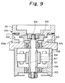
- Fig. 9 is a fragmentary sectional view of a conventional drum motor for a VCR.
- a rotating shaft 104 is rotatably supported by the inner peripheral surface 101a of the bottom center of a motor casing 101 and the inner peripheral surface 101b of the top center of the motor casing 101 through ball bearings 102 and 103.
- a flange 105 is secured to the outer periphery of the upper end of the rotating shaft 104 so that a rotor-side unit 110 can be mounted thereon.
- a rotor magnet 106 of a motor part for driving the rotating shaft 104 to rotate is coaxially secured to the outer periphery of the central portion of the rotating shaft 104 through a cylindrical back yoke 107 made of a magnetic material or the like.
- a stator core 108 is secured to the inner peripheral surface of the motor casing 101 in opposing relation to the rotor magnet 106.
- a stator-side unit 109 is generally secured to the top of the motor casing 101, whereas the rotor-side unit 110 is secured to the flange 105 to constitute a drum unit.
- a magnetic tape for recording is wound on both the outer peripheral surface 109a of the stator-side unit 109 and the outer peripheral surface 110a of the rotor-side unit 110, and in this state, the tape is fed at a constant speed so that recording tracks are provided on the magnetic tape by means of a magnetic head 111 attached to the rotor-side unit 110a.
- the magnitude of vibration of the rotating shaft 104 depends on the bearing clearance of the ball bearings 102 and 103.
- the vibration in the radial direction is substantially equal to the radial clearance of the ball bearings 102 and 103, while the vibration in the thrust direction is substantially equal to the thrust clearance of the ball bearings 102 and 103.
- various schemes have been devised, for example, application of preload to the ball bearings 102 and 103.
- the non-repeatable run out i.e.
- the non-repeatable component of vibration in the radial and axial directions which cannot be removed even after coaxial machining of the flange to remove vibration thereof, is of the order of 0.3 to 0.5 microns, and the minimization of the vibration of the rotating shaft 104 has already reached the limit due to problems peculiar to ball bearings.
- the vibration of the rotating shaft 104 is a serious obstacle to the achievement of a higher recording density on magnetic tape.
- a drum motor that employs hydrodynamic bearings, as shown in Japanese Patent Application Post-Exam Publication No. 63-64645.
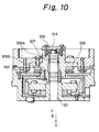
- Fig. 10 schematically shows the structure of this drum motor. Referring to Fig. 10, a disc 123 is rotatably fitted on a fixed shaft 121, and a thrust bearing member 124 is attached to the top of the disc 123.
- the fixed shaft 121 is provided at two portions thereof with radial grooves 126A and 126B, which constitute a radial hydrodynamic bearing in combination with the inner peripheral surface of the disc 123.
- the end surface of the fixed shaft 121 and the thrust bearing member 124, which faces it, constitute in combination a thrust hydrodynamic bearing.
- the disc 123 is rotatably supported on the fixed shaft 121 without coming into solid contact with it. Accordingly, it is possible to rotate the disc 123 smoothly with minimal vibration and high accuracy in comparison to the conventional drum motor employing ball bearings.
- the thrust load bearing direction is limited to one. Therefore, the force that is produced in the thrust hydrodynamic bearing during the rotation of the rotating shaft is equal to the thrust load and will never exceed it.
- the amount of levitation of the thrust bearing is a function of the hydrodynamic force and the thrust load. Therefore, if the thrust load changes due to a change of the position or attitude in which the motor is used, the amount of thrust levitation changes substantially according to the change in the thrust load. For example, when the motor is used in a horizontal position, the thrust load is approximately zero, and the amount of thrust levitation is infinite. In an extreme case, the rotor-side unit may fall off and break down.
- the conventional drum motor is arranged such that a change in the amount of levitation of the thrust bearing due to a change of the position in which the motor is used, that is, a change in the relative height of the rotor-side unit relative to the stationary-side unit in the thrust direction, is reduced by using the axial attraction force of a permanent magnet 138, thereby enabling the motor to be used even in a horizontal position.
- the permanent magnet 138 is disposed to face an iron piece 142 to exert an attraction force in the downward direction, i.e., the direction of the arrow X.
- the attraction force of the permanent magnet 138 and the weight of the rotor act in the same direction
- the thrust load is the sum of the attraction force of the permanent magnet and the weight of the rotor, which increases the wear of sliding surfaces of the bearing members.
- the thrust bearing is composed of the end surface of the fixed shaft 121 and the thrust bearing member 124, which faces it. Therefore, the outer diameter of the thrust dynamic pressure generating surface cannot be increased as desired, and hence the thrust load bearing capacity is low relative to the radial load bearing capacity. Accordingly, a high-viscosity fluid, e.g., lubricating oil, is used in this type of hydrodynamic bearing because if a non-viscosity fluid like air is employed, the load bearing capacity, particularly that of the thrust bearing is insufficient in general.
- the viscosity of lubricating oil shows a logarithmic change with temperature and becomes particularly high at low temperatures. This implies that a temperature change causes a change in the amount of levitation of the thrust bearing, leading to a change in the relative height of the rotor-side unit and other problems related thereto.
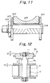
- Fig. 11 schematically shows the H-shaped bearing structure.
- two thrust plates 203 are brought into direct contact with both end surfaces of a radial bearing member 205, and these plates and bearing member are secured to a fixed shaft 204 by tightening a nut 208, for example.
- the two thrust plates 203 are provided with respective dynamic pressure generating parts 209 such that the directions of dynamic pressures generated are opposite to each other.
- the bearing rigidity in the thrust direction is determined by clearances at both ends of the thrust bearing.
- the bearing rigidity can be enhanced, and it is possible to realize a hydrodynamic bearing having high rigidity even if air is employed as a fluid.
- a bearing having the structure shown in Fig. 11 also suffers from problems. For example, if an improper torque is applied for tightening the nut 208, the thrust plates 203 are deformed. As a result, the expected uniform clearances cannot be ensured, and the expected bearing performance cannot be obtained. To cope with such problems, attempts have been made to minimize the deformation of the thrust plates 203, for example, by setting the tightening torque at a level which is a fraction of the standard value (i.e., the torque at which the tensile force arising from the axial force caused by the bolt tightening torque reaches 70% of the yield point of the material concerned). With this method, however, it is impossible to sufficiently ensure the force required to secure the rotor-side bearing member to the rotating shaft. Accordingly, when the shaft-side members are used as a rotor in the above-described H-shaped bearing structure, reliability during high-speed rotation is unsatisfactory in view of the influence of centrifugal force acting on the bearing during rotation.
- a rotating shaft 5 is provided with a flange 10 for mounting a rotor-side unit, e.g., a recording head, a rotary drum, etc., as shown in Fig. 12, since the rotor-side unit is mounted directly on the flange 10, the accuracy of rotation of the flange 10, i.e. coaxial rotation of the flange and the rotary shaft, directly determines the accuracy of rotation of the rotor-side unit. Therefore, it is necessary in order to realize higher recording densities of VCR to raise the rotational accuracy of the flange 10.
- the flange 10 is secured to the rotating shaft 5 by means, for example, of using a locking member, e.g., a locking nut 11 which clamps the center portion of the flange.
- a locking member e.g., a locking nut 11 which clamps the center portion of the flange.
- the machined surface 10b is deformed with time, as shown by a2 in Fig. 12, even after the flange 10 has been machined coaxially, by the clamping stress, i.e. uneven residual stress in the flange, imposed by the locking nut 11, for example, thus giving rise to problems such as an increase in the run-out of the machined surface 10b.
- the clamping stress exerted by the locking nut 11 causes deformation of a stepped portion 5a provided on the rotating shaft 5 and further causes a rotor-side bearing member 17 to be deformed as shown by a1 in the figure.
- an increase in the axial dimension l1 results in an increase in the overall length of the rotating shaft 5.
- such a conventional practice is an obstacle to a reduction in the overall size of the motor.
- the flange 10 is made of the same material as that used to form a rotary drum or other member mounted thereon, e.g., an aluminum alloy, because the coefficient of linear expansion of the flange 10 needs to be coincident with that of the member mounted thereon.
- the rotating shaft is formed by using stainless steel or other similar material in many cases, although it is different in the coefficient of linear expansion from a material used for the bearing members, e.g., a ceramic material, by taking into consideration the rigidity and workability of such material.
- the rotor is composed of a combination of different kinds of materials, which have different coefficients of linear expansion, and it is likely that the bearing members and the flange will be deformed or displaced at the joint due to a change in temperature. Accordingly, it is extremely difficult to maintain rotation of high accuracy over the entire range of temperatures at which the motor is used.
- the present invention provides a drum motor for VCR including radial and thrust hydrodynamic bearings which are composed of a rotor-side bearing member formed by bringing a pair of first and second thrust plates, at least sliding portions of which are made of a ceramic material, into direct contact with both end surfaces, respectively, of a cylindrical radial bearing member at least a sliding portion of which is made of a ceramic material, and integrating the first and second thrust plates and the radial bearing member into one unit, and a stator-side bearing member comprised of a cylindrical radial sleeve, at least sliding portions of which are made of a ceramic material.
- the radial sleeve is disposed to face the rotor-side bearing member so that the inner peripheral surface and both end surfaces of the radial sleeve respectively cooperate with the outer peripheral surface of the radial bearing member and the mutually facing surfaces of the first and second thrust plates.
- a rotating shaft extends through a through-hole provided in the center of the rotor-side bearing member.
- the rotor-side bearing member is secured to the rotating shaft by a locking member provided on the rotating shaft.
- the drum motor further includes a rotor magnet of a motor part for driving the rotating shaft to rotate.
- the rotor magnet is secured to the rotating shaft.
- a motor casing is secured at the inner peripheral surface thereof to the outer peripheral surface of the radial sleeve.
- a stator unit is secured to the motor casing so as to face the rotor magnet of the motor part. Further, a dynamic pressure generating groove is provided on either each end surface of the radial sleeve, or each of the mutually facing surfaces of the first and second thrust plates.
- the rotating shaft has a stepped portion with an enlarged radius which is defined by a radially extended portion of the rotating shaft, and an abutting surface defined by a flat surface of the stepped portion which extends at right angles to the axial direction of the rotating shaft.
- One end surface of the first thrust plate is in direct contact with the abutting surface.
- the rotor magnet is axially secured to a cylindrical back yoke made of a magnetic material.
- the rotating shaft extends through a through-hole provided in the center of the back yoke.
- the back yoke has a flat end surface extending at right angles to the through-hole of the back yoke.
- the end surface of the back yoke is in direct contact with one end surface of the second thrust plate.
- the rotating shaft, the rotor-side bearing member, the first and second thrust plates and the back yoke are integrated into one unit by axially pressing the rotor-side bearing member, the first and second thrust plates and the back yoke against the abutting surface with a predetermined pressure by using the locking member provided on the rotating shaft.
- At least one of the outer diameters of the abutting surface and the end surface of the back yoke is approximately equal to the outer diameter of the radial bearing member.
- the present invention provides a drum motor for a VCR including a rotating shaft having a flange for mounting a rotor-side unit including a rotary drum and a recording head thereon, and a hydrodynamic bearing for rotatably supporting the rotating shaft.
- the hydrodynamic bearing includes radial and thrust hydrodynamic bearings composed of a rotor-side bearing member formed by bringing a pair of first and second thrust plates, at least the sliding portions of which are made of a ceramic material, into direct contact with both end surfaces, respectively, of a cylindrical radial bearing member at least a sliding portion of which is made of a ceramic material, and integrating the first and second thrust plates and the radial bearing member into one unit, and a stator-side bearing member comprised of a cylindrical radial sleeve, at least sliding portions of which are made of a ceramic material.
- the radial sleeve is disposed to face the rotor-side bearing member so that the inner peripheral surface and both end surfaces of the radial sleeve respectively cooperate with the outer peripheral surface of the radial bearing member and the mutually facing surfaces of the first and second thrust plates.
- the rotating shaft extends through a through-hole provided in the center of the rotor-side bearing member.
- the rotor-side bearing member is secured to the rotating shaft by a locking member provided on the rotating shaft.
- the drum motor further includes a rotor magnet of a motor part for driving the rotating shaft to rotate.
- the rotor magnet is secured to the rotating shaft.
- a motor casing is secured at the inner peripheral surface thereof to the outer peripheral surface of the radial sleeve.
- a stator unit is secured to the motor casing so as to face the rotor magnet of the motor part. Further, a dynamic pressure generating groove is provided on either each end surface of the radial sleeve, or each of the mutually facing surfaces of the first and second thrust plates.
- the rotating shaft has a stepped portion with an enlarged radius which is defined by a radially extended portion of the rotating shaft, and a pair of first and second abutting surfaces respectively defined by flat surfaces of the stepped portion which extend at right angles to the axial direction of the rotating shaft.
- One end surface of the first thrust plate is in direct contact with the first abutting surface.
- the rotor magnet is axially secured to a cylindrical back yoke made of a magnetic material.
- the rotating shaft extends through a through-hole provided in the center of the back yoke.
- the back yoke has a flat end surface extending at right angles to the through-hole of the back yoke.
- the end surface of the back yoke is in direct contact with one end surface of the second thrust plate.
- the rotor-side bearing member, the first and second thrust plates and the back yoke are axially pressed against the first abutting surface with a predetermined pressure by using a first locking member provided on the rotating shaft.
- the flange has a through-hole provided in the center thereof.
- the rotating shaft extends through the through-hole of the flange so that one end surface of the flange faces the end surface of the first thrust plate across the stepped portion and is brought into direct contact with the second abutting surface.
- the flange is axially pressed against the second abutting surface with a predetermined pressure by using a second locking member provided on the rotating shaft, thereby integrating the flange and the rotating shaft into one unit.
- At least one of the outer diameters of the first and second abutting surfaces, the end surface of the back yoke and the end surface of the flange is approximately equal to the outer diameter of the radial bearing member.
- the pressures applied by the first and second locking members are axially counter to each other and approximately equal to each other in magnitude.
- the drum motor further includes means for effecting proper adjustment for a position in which the motor is installed, which includes preload generating means for previously magnetically generating force counter to a thrust load attributable to the weight of the motor rotor and so forth in the range of from a level approximately half the thrust load to a level approximately equal to it.
- the preload generating means includes a second magnet disposed so as to cooperate with the rotating shaft to form a magnetic circuit, thereby previously generating force counter to the thrust load by magnetic force from the magnet.
- At least the stepped portion of the rotating shaft is made of a magnetic material so that the stepped portion cooperates with the second magnet to form the magnetic circuit.
- the motor part comprises a radial gap type magnetic circuit, and the preload generating means is arranged to previously generate a force counter to the thrust load by axially offsetting the magnetic center of the stator core of the motor part and the magnetic center of the rotor magnet from each other.
- a dynamic pressure generating groove is provided on either the outer peripheral surface of the radial bearing member or the inner peripheral surface of the radial sleeve.
- a sliding portion of at least either of the radial and thrust bearing members is made of a ceramic material, e.g., silicon carbide or alumina.
- the perpendicularity between the outer peripheral surface of the radial bearing member and each of the mutually facing surfaces of the thrust plates, which are in direct contact with both end surfaces of the radial bearing member, can readily be realized by accurately forming the thrust plates and the radial bearing member so that the thrust plates have the required flatness and the required perpendicularity is attained between each end surface of the radial bearing member and the outer peripheral surface thereof, and securing these members to the rotating shaft by using a locking member, e.g., a locking nut.
- a predetermined clearance can be obtained by properly setting machining dimensions for the outer peripheral surface of the radial bearing member and the inner peripheral surface of the radial sleeve.
- a predetermined clearance can readily be realized by ensuring the required height difference between the radial bearing member and the radial sleeve.
- ceramic parts which are excellent in the machining accuracy in their single part state, are brought into direct contact with each other without interposition and integrated into one unit, excellent assembling accuracy can be obtained.
- the bearing structure Since the radial bearing member and the two thrust plates, which are secured to the rotating shaft, each face the radial sleeve across a narrow clearance, these members are uniformly pressed by sufficiently high dynamic pressures applied in the thrust and radial directions during rotation. Accordingly, the bearing structure has sufficiently high rigidity to satisfactorily endure external force or the like irrespective of the position of the motor in which it is operated. Thus, the motor is capable of rotating with extremely high accuracy and with minimal vibration.
- the hydrodynamic bearings of the present invention have advantages in that the load bearing capacity, bearing torque and other performance of the bearings show an extremely small change with respect to a change in temperature, and that there is no possibility of the working fluid drying up, and further that no peripheral parts will be contaminated.
- the bearing rigidity is 2,300 gf/ ⁇ m in the thrust direction and 2,200 gf/ ⁇ m in the radial direction.
- the bearing rigidity in the thrust direction is raised relative to that in the radial direction in accordance with the purpose of use. For example, when the weight of the rotor is about 400 g, if the motor is used in a position where the rotating shaft extends vertically upward, the thrust load is about 400 gf, whereas, when the motor is used in a position where the rotating shaft extends horizontally, the thrust load is zero. Accordingly, the change of the thrust load due to a change of the position of the rotating shaft is 400 gf at maximum.
- the displacement of the rotating shaft in the thrust direction at the time of change of the position of the rotating shaft or attitude of the hydrodynamic bearings is determined by the bearing rigidity in the thrust direction. In the embodiment of the present invention, it is about 0.17 ⁇ m.
- the motor of the present invention can be used in an inverted position without any practical problem.
- it is made possible to minimize a change of the relative height of the rotating shaft with respect to a change in the operating position of the motor, which is particularly important. Particularly excellent effects can be expected when the bearing structure of the present invention is used for a drum motor for a VCR.
- the run-out of the rotating shaft in the embodiment of the present invention is about 1/10 to about 1/20 of that in the conventional drum motor employing ball bearings in both the radial and thrust directions in the rotational speed range of from 1,800 rpm to 5,000 rpm, which is the service rotational speed range of drum motors.
- the members which are to be locked are clamped by applying a predetermined level of force with a locking member, e.g., a locking nut, through a coned disc spring or other similar spring. Further, the outer diameters of the respective abutting surfaces of the members to be locked are made equal to each other so that the clamping stress is leveled out.
- a locking member e.g., a locking nut
- the outer diameters of the respective abutting surfaces of the members to be locked are made equal to each other so that the clamping stress is leveled out.
- the fit clearance between the rotating shaft and the through-hole in the rotor-side bearing member where the rotating shaft extends and is secured is set so as to be approximately zero at the maximum service temperature of the motor. That is, a clearance fit is employed (the coefficient of linear expansion of the shaft is greater than that of the bearing member). Accordingly, the radial displacement of the rotor-side bearing member relative to the rotating shaft, which is caused by a difference in the coefficient of linear expansion between the materials of the two members, occurs reversibly and coaxially with respect to the rotating shaft by virtue of fact that the fit clearance between the rotating shaft and the through-hole is minimized in combination with the fact that the clamping stress imposed on the abutting surfaces is leveled out, as described above.
- any change in the run-out of the rotating shaft due to a temperature change is extremely small.
- the rotor-side bearing member is made of a brittle material, e.g., a ceramic material, it is possible to prevent damage to the rotor-side bearing member.
- the manner in which the rotating shaft fits the through-hole in the flange, where the rotating shaft extends and is secured, is specified as being an interference fit (the coefficient of linear expansion of the flange is greater than that of the shaft) so that the fit clearance is approximately zero at the maximum service temperature of the motor. Accordingly, it is possible to minimize displacement of the flange relative to the rotating shaft and deformation thereof due to a temperature change. Thus, it is possible to maintain a stable performance, attended with minimal run-out, over the entire range of temperatures at which the motor is used.
- the apparent thrust load can be made approximately zero by magnetically generating force counter to the thrust load attributable to the weight of the rotor.
- the loss torque in the thrust bearing at the time of starting can be made approximately zero.
- the sliding portions are formed by using a ceramic material, e.g., silicon carbide or alumina, which is excellent in wear resistance and slip properties. Accordingly, it is possible to save electric power at the time of starting and to eliminate damage to the thrust bearing members which might otherwise occur when the motor is started and stopped. Thus, the durability to the repetition of start and stop also improves by a large margin in comparison to the prior art.
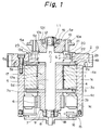
- Fig. 1 is a sectional view showing the structure of the drum motor for a VCR according to the present invention.
- a cylindrical radial bearing member 1 is made of a ceramic material.
- a pair of first and second thrust plates 2 and 3, which are made of a ceramic material, are in direct contact with both end surfaces, respectively, of the radial bearing member 1.
- a cylindrical radial sleeve 4 is made of a ceramic material.
- the radial sleeve 4 is supported at its inner peripheral surface 4a and end surfaces 4b and 4c by the outer peripheral surface 1a of the radial bearing member 1 and the mutually facing surfaces 2a and 3a of the first and second thrust plates 2 and 3, respectively, so that the radial bearing member 1 is rotatably supported by the radial sleeve 4.
- the outer peripheral surface 1a of the radial bearing member 1 and the inner peripheral surface 4a of the radial sleeve 4 constitute in combination a radial hydrodynamic bearing, while the mutually facing surfaces 2a and 3a of the first and second thrust plates 2 and 3 constitute a thrust hydrodynamic bearing in combination with the two end surfaces 4b and 4c of the radial sleeve 4.
- a rotating shaft 5 extends through a through-hole provided in the rotor-side bearing member 17, which is formed by bringing the first and second thrust plates 2 and 3 into contact with both end surfaces of the cylindrical radial bearing member 1 and integrating them into one unit.
- the rotating shaft 5 has a stepped portion 5a with an enlarged radius which is defined by a radially extended portion of the rotating shaft 5, and a first abutting surface 5b defined by a flat surface of the stepped portion 5a which extends at right angles to the axial direction.
- One end surface 2b of the first thrust plate 2 is in direct contact with the first abutting surface 5b.
- a rotor magnet 6 of a motor part for driving the rotating shaft 5 to rotate is coaxially secured to a cylindrical back yoke 7 made of a magnetic material.
- the rotating shaft 5 extends through a through-hole provided in the center of the back yoke 7.
- One end surface 7a of the back yoke 7 is in direct contact with one end surface 3b of the second thrust plate 3.
- the rotor-side bearing member 17 and the back yoke 7 are integrated into one unit by pressing them with a predetermined pressure by using a locking nut 8 which is provided on the lower end of the rotating shaft 5. It should be noted that a coned disc spring 9 is interposed between the locking nut 8 and the back yoke 7.
- a flange 10 for mounting a rotor-side unit comprising a rotary drum and a recording head is pierced with the rotating shaft 5 extending through a through-hole provided in the center thereof.
- One end surface 10a of the flange 10 is in direct contact with a second abutting surface 5c provided on the stepped portion 5a.
- the flange 10 and the rotating shaft 5 are integrated into one unit by pressing them with a predetermined pressure by using a locking nut 11 which is provided on the upper end of the rotating shaft 5.
- a coned disc spring 12 is interposed between the locking nut 11 and the flange 10.
- a motor casing 13 is secured to the outer peripheral surface of the radial sleeve 4, and a stator unit 14 is secured to the inner peripheral surface of the motor casing 13 in opposing relation to the rotor magnet 6.
- reference numeral 15 denotes a Hall element substrate for detecting the radial position of the rotor magnet 6
- reference numeral 16 denotes a ring-shaped FG magnet which is disposed so as to cooperate with a comb-like coil printed on the Hall element substrate 15 to constitute a frequency generator for detecting the axial position of the rotor side unit.
- the mutually facing surfaces 2a and 3a of the first and second thrust plates 2 and 3, which are rotating members of the thrust hydrodynamic bearing, are provided with respective dynamic pressure generating grooves, e.g., spiral dynamic pressure generating grooves C1 as shown in Fig. 2.
- the two end surfaces 4b and 4c of the radial sleeve 4, which is a stationary member of the thrust hydrodynamic bearing are smoothed.
- both end portions of the outer peripheral surface 1a of the radial bearing member 1, which is a rotating member of the radial hydrodynamic bearing are provided with dynamic pressure generating grooves, e.g., herringbone-shaped dynamic pressure generating grooves D1 as shown in Fig. 3.
- the inner peripheral surface 4a of the radial sleeve 4, which is a stationary member of the radial hydrodynamic bearing is smoothed.
- members which are provided with such dynamic pressure generating grooves are not limited to the rotating members.
- the arrangement may be such that spiral dynamic pressure generating grooves are provided on the two end surfaces 4b and 4c of the radial sleeve 4, which is a stationary member, and herringbone-shaped dynamic pressure generating grooves are provided on the inner peripheral surface 4a of the radial sleeve 4, whereas the mutually facing surfaces 2a and 3a of the first and second thrust plates 2 and 3, which are rotating members, together with the outer peripheral surface 1a of the radial bearing member 1 (which is also a rotating member), are smoothed.
- the radial hydrodynamic bearing used in the drum motor for a VCR may be provided with no radial dynamic pressure generating groove. That is, the rotational speed of a drum motor for a VCR is of the order of 1,800 rpm to 3,600 rpm. In such a rotational speed range, which is relatively low for hydrodynamic bearings, there is substantially no difference in bearing rigidity between cylindrical bearings having no radial dynamic pressure generating groove and bearings provided with radial dynamic pressure generating grooves. There are cases where the bearing rigidity of cylindrical bearings is rather higher than that of bearings provided with radial dynamic pressure generating grooves under certain conditions.
- the perpendicularity between the outer peripheral surface 1a of the radial bearing member 1 and the mutually facing surfaces 2a and 3a of the first and second thrust plates 2 and 3 after these members have been assembled together to constitute a hydrodynamic bearing is important for uniformly forming a thin air film on each dynamic pressure generating surface and also for enhancing the bearing rigidity.
- the required accuracy can be reproduced even after they have been assembled together, by clamping these members with the locking nut 8. That is, it is possible to obtain a remarkably high degree of assembling accuracy by bringing ceramic members, which are excellent in the machining accuracy in their single part state, into direct contact with each other without interposition and integrating them into one unit. Accordingly, it is possible to readily realize a hydrodynamic bearing having high bearing rigidity, in which a narrow clearance is uniformly ensured.
- the end surface 2b of the first thrust plate 2 is brought into direct contact with the first abutting surface 5b, while the end surface 7a of the back yoke 7 is brought into direct contact with the end surface 3b of the second thrust plate 3, and a spring 9, for example, a coned disc spring or a coil spring, having an appropriate spring constant is interposed between the locking nut 8 and the back yoke 7.
- a spring 9 for example, a coned disc spring or a coil spring, having an appropriate spring constant is interposed between the locking nut 8 and the back yoke 7.
- the locking nut 8 is tightened within the elastically deformable range of the spring 9. Consequently, the rotor-side bearing member 17 is uniformly pressed in the axial direction by a predetermined pressure.
- the rotor-side bearing member 17 can be secured to the rotating shaft 5 without applying excess force thereto.
- the rotor-side bearing member 17 is secured to the rotating shaft 5 by applying force which is sufficient to secure the thrust plates 2 and 3 and the radial bearing member 1 to the rotating shaft 5, and yet which minimizes the deformation of the rotor-side bearing member 17 due to the clamping stress.
- the stress which would cause the rotor-side bearing member 17 to be deformed even after the assembly, is effectively relaxed by properly controlling the perpendicularity of the first abutting surface 5b with respect to the center hole of the rotor-side bearing member 17 and the perpendicularity of the end surface 7a of the back yoke 7 with respect to the center hole of the back yoke 7.
- the constituent elements can be assembled together without lowering the machining accuracy of these elements in their single part state.
- the outer diameter of the first abutting surface 5b and that of the end surface 7a of the back yoke 7 are made approximately equal to the outer diameter of the radial bearing member 1.
- the abutting surfaces of the thrust plates 2 and 3 are axially pressed by uniform force over the entire area of each abutting surface even after the clamping process. Accordingly, it is possible to minimize warpage or other deformation of the thrust plates 2 and 3 due to the clamping stress.
- the warpage a1 of the thrust plates 2 and 3 after assembly is not more than 0.2 ⁇ m, whereas in the conventional bearing structure it has been 1 ⁇ m or more, as shown in Fig. 4.
- the flange end surface 10a is brought into direct contact with the second abutting surface 5c, and a spring 12, e.g., a coned disc spring or a coil spring, having an appropriate spring constant, is interposed between the locking nut 11 and the flange 10. Then, the locking nut 11 is tightened within the elastically deformable range of the spring 12 in the same way as the above.
- a spring 12 e.g., a coned disc spring or a coil spring, having an appropriate spring constant
- the second abutting surface 5c is uniformly pressed in the axial direction by a predetermined pressure, thereby enabling the flange 10 to be secured to the rotating shaft 5 in such a manner that the deformation of the stepped portion 5a and the rotor-side bearing member 17 due to the clamping stress is minimized.
- the outer diameter of the second abutting surface 5c and that of the end surface 10a of the flange 10 are made approximately equal to each other.
- the abutting end surface 10a of the flange 10 is axially pressed uniformly over the entire area thereof even after the clamping process. Accordingly, it is possible to reduce the change of the rotor-side unit mounting surface 10b of the flange 10 with time due to the clamping stress. It is also possible to further minimize the deformation of the stepped portion 5a and the rotor-side bearing member 17.
- the clamping force applied by the first locking member (the locking nut 8 and the coned disc spring 9) and the clamping force by the second locking member 19 (the locking nut 11 and the coned disc spring 12) are made approximately equal to each other so that the surface pressures applied to the first and second abutting surfaces 5b and 5c are equal to each other.
- the deformation of the stepped portion 5a due to uneven clamping stress is reduced, and the deformation of the rotor-side bearing member 17 due to uneven clamping stress is also reduced.
- the rotor-side bearing member 17 is formed by using a brittle material, e.g., a ceramic material, it is also possible to prevent damage to the rotor-side bearing member 17 caused by a difference in the coefficient of linear expansion between the materials of the two members.
- a brittle material e.g., a ceramic material
- a ring-shaped second magnet 20 and two yoke plates 21 and 22 are coaxially secured to a cylindrical sleeve 23, made of a non-magnetic material, so as to abut on the second magnet 20.
- the outer periphery of the sleeve 23 is provided with a thread, which is in engagement with a thread provided on the inner peripheral surface 13a of the top of the motor casing 13.
- the sleeve 23 is axially movably secured.
- the second magnet 20 has been magnetized, for example, SN, in the direction of the axis (thickness) thereof to form a magnetic circuit through the two yoke plates 21 and 22 and the outer peripheral surface 5g of the stepped portion 5a of the rotating shaft 5.
- the flange 10 is made of a non-magnetic material, e.g., aluminum, and it is not concerned with forming the magnetic circuit.
- the center of the two yoke plates 21 and 22 and the center of the stepped portion 5a are axially offset from each other by ⁇ 1, thereby axially generating magnetic attraction force (preload) F1 counter to the thrust load.
- ⁇ 1 The relationship between ⁇ 1 and the attraction force is such as that shown in Fig. 5.
- the attraction force F1 can be adjusted in the range of from approximately 1/2 of the thrust load to a level approximately equal to the thrust load.
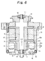
- the drum motor may be arranged as shown in Fig. 6. That is, the magnetic center of the stator core of the stator unit 14 and the magnetic center of the rotor magnet 6 are axially offset from each other by ⁇ 2, thereby generating axial attraction force F2.
- the attraction force F2 can be set to an appropriate value through adjustment of ⁇ 2 by changing the axial thickness of a ring-shaped shim 24 inserted in between the end portion 14a of the stator core of the stator unit 14 and the abutting surface 13b of the motor casing 13.
- the drum motor in a case where the drum motor is used only in a state where the rotating shaft 5 extends vertically upward, it is preferable to nullify the apparent thrust load by making the preload approximately equal to the thrust load.
- the preload may be set at a level approximately half the weight of the rotor.
- the thrust load applied to the sliding surfaces on the first thrust plate side is approximately half the weight of the rotor
- the thrust load applied to the sliding surfaces on the second thrust plate side is approximately half the weight of the rotor
- first and second thrust plates 2 and 3 are all made of a ceramic material
- each of these members is not necessarily limited to the one the whole of which is made of a ceramic material, and that only sliding portions of these members may be formed from a ceramic material according to circumstances.
- the present invention is applied to a radial gap type of motor
- the present invention is not necessarily limited to the radial gap type of motor but may also be applied to an axial gap type of motor such as that shown in Fig. 7. That is, the motor structure may be such that a rotor magnet 6 is secured to the lower end surface of a back yoke 7, and a stator unit 14 is provided so as to face the rotor magnet 6 across a gap in the axial direction of the rotating shaft 5.
- the thrust load additionally includes the attraction force of the rotor magnet 6 acting in the thrust direction.
- Fig. 8 shows the drum motor for VCR having the structure shown in Fig. 1, which is equipped with a rotor-side unit 25 and a stator-side unit 26.
- the present invention provides the following excellent effects:
Landscapes
- Engineering & Computer Science (AREA)
- General Engineering & Computer Science (AREA)
- Mechanical Engineering (AREA)
- Power Engineering (AREA)
- Chemical & Material Sciences (AREA)
- Oil, Petroleum & Natural Gas (AREA)
- Ceramic Engineering (AREA)
- Physics & Mathematics (AREA)
- Fluid Mechanics (AREA)
- Sliding-Contact Bearings (AREA)
- Motor Or Generator Frames (AREA)
- Connection Of Motors, Electrical Generators, Mechanical Devices, And The Like (AREA)
Applications Claiming Priority (2)
| Application Number | Priority Date | Filing Date | Title |
|---|---|---|---|
| JP244181/92 | 1992-08-20 | ||
| JP4244181A JPH0668439A (ja) | 1992-08-20 | 1992-08-20 | Vtr用ドラムモーター |
Publications (2)
| Publication Number | Publication Date |
|---|---|
| EP0583790A2 true EP0583790A2 (de) | 1994-02-23 |
| EP0583790A3 EP0583790A3 (en) | 1994-05-18 |
Family
ID=17114975
Family Applications (1)
| Application Number | Title | Priority Date | Filing Date |
|---|---|---|---|
| EP19930113355 Withdrawn EP0583790A3 (en) | 1992-08-20 | 1993-08-20 | Drum motor for vcr |
Country Status (3)
| Country | Link |
|---|---|
| US (1) | US5471104A (de) |
| EP (1) | EP0583790A3 (de) |
| JP (1) | JPH0668439A (de) |
Cited By (4)
| Publication number | Priority date | Publication date | Assignee | Title |
|---|---|---|---|---|
| EP0825355A3 (de) * | 1996-08-23 | 1998-11-18 | Eastman Kodak Company | Luftgeschmiertes hydrodynamisches Keramiklager |
| GB2330179B (en) * | 1997-04-23 | 2001-04-11 | Seagate Technology | Spindle motor with multiple thrust plate fluid dynamic bearing |
| WO2003019753A3 (en) * | 2001-08-27 | 2004-03-18 | Colibri Spindles Ltd | Spindle motor |
| CN107809151A (zh) * | 2016-09-08 | 2018-03-16 | 博格华纳公司 | 用于轴承的具有延伸肩部的电机转子 |
Families Citing this family (19)
| Publication number | Priority date | Publication date | Assignee | Title |
|---|---|---|---|---|
| US5834870A (en) * | 1994-04-28 | 1998-11-10 | Hitachi, Ltd. | Oil impregnated porous bearing units and motors provided with same |
| US5793561A (en) * | 1994-10-14 | 1998-08-11 | Canon Kabushiki Kaisha | Rotary drum assembly having dynamic-pressure generating mechanism between rotary shaft and bearing |
| KR960018713U (ko) * | 1994-11-21 | 1996-06-19 | 헤드드럼 조립체 | |
| JPH10184302A (ja) * | 1996-11-11 | 1998-07-14 | Daikin Ind Ltd | 流体機械 |
| JP3266559B2 (ja) * | 1997-08-26 | 2002-03-18 | 三星電機株式会社 | ブラシレスdcモータ |
| EP1024294A3 (de) * | 1999-01-29 | 2002-03-13 | Ibiden Co., Ltd. | Motor und Turbomolekularpumpe |
| US6747383B2 (en) * | 2002-04-09 | 2004-06-08 | Honeywell International, Inc. | Generator with hydraulically mounted stator rotor |
| JP2004266891A (ja) * | 2003-02-25 | 2004-09-24 | Matsushita Electric Ind Co Ltd | 動圧気体軸受モータ |
| JP4461180B2 (ja) * | 2004-09-22 | 2010-05-12 | ハミルトン・サンドストランド・コーポレイション | モーター冷却経路およびスラストベアリング負荷設計 |
| US7956499B2 (en) * | 2005-06-02 | 2011-06-07 | Seagate Technology Llc | Motor magnetic force attenuator |
| JP4483899B2 (ja) * | 2007-06-21 | 2010-06-16 | 日産自動車株式会社 | アキシャルギャップ型回転電機の交流制御装置 |
| CN101833354B (zh) * | 2009-03-13 | 2013-07-31 | 鸿富锦精密工业(深圳)有限公司 | 旋转控制系统及方法 |
| US8411389B1 (en) * | 2010-06-29 | 2013-04-02 | Western Digital Technologies, Inc. | Disk drive fluid dynamic bearing spindle |
| KR101218995B1 (ko) * | 2011-06-03 | 2013-01-04 | 삼성전기주식회사 | 모터 |
| DE102012016003A1 (de) * | 2012-08-11 | 2014-05-15 | Minebea Co., Ltd. | Fluiddynamisches Lagersystem |
| CN104756373B (zh) * | 2014-06-30 | 2018-06-05 | 深圳市大疆灵眸科技有限公司 | 云台电机及云台 |
| JP6533008B2 (ja) * | 2016-03-07 | 2019-06-19 | 日立オートモティブシステムズ株式会社 | スタータモータ |
| KR102152714B1 (ko) * | 2019-05-28 | 2020-09-07 | 엘지전자 주식회사 | 모터 어셈블리 및 그 제조 방법 |
| CN117145859B (zh) * | 2023-10-16 | 2026-03-20 | 江苏翰琪电机股份有限公司 | 动压轴承高速电主轴及动压轴承 |
Family Cites Families (10)
| Publication number | Priority date | Publication date | Assignee | Title |
|---|---|---|---|---|
| FR1372560A (fr) * | 1963-07-31 | 1964-09-18 | Rech S Magnetiques Soc Et | Asservissement magnétique |
| DE2404325A1 (de) * | 1974-01-30 | 1975-07-31 | Skf Kugellagerfabriken Gmbh | Rollenlagerung in textilmaschinen |
| DE2535852C2 (de) * | 1975-08-12 | 1984-05-17 | Teldix Gmbh, 6900 Heidelberg | Elektrische Maschine |
| JPS5712828A (en) * | 1980-06-16 | 1982-01-22 | Carus Corp | Rare-earth metal-manganese oxydizing catalyst and its manufacture |
| JPS61204864A (ja) * | 1985-03-08 | 1986-09-10 | Hitachi Ltd | 回転ドラム装置 |
| JPS63176813A (ja) * | 1987-01-19 | 1988-07-21 | Hitachi Ltd | 軸受装置 |
| JPS63213453A (ja) * | 1987-03-02 | 1988-09-06 | Shinano Totsuki Kk | マグネツトロ−タ形直流モ−タの回転音低減構造 |
| JPH0255546A (ja) * | 1988-08-16 | 1990-02-23 | Nec Corp | 電動機 |
| JP2826156B2 (ja) * | 1990-03-15 | 1998-11-18 | イビデン株式会社 | スピンドルモータ |
| US5019738A (en) * | 1990-07-16 | 1991-05-28 | Lincoln Laser Company | Self-pressurizing gas supported surface-roughness bearing |
-
1992
- 1992-08-20 JP JP4244181A patent/JPH0668439A/ja active Pending
-
1993
- 1993-08-19 US US08/109,706 patent/US5471104A/en not_active Expired - Fee Related
- 1993-08-20 EP EP19930113355 patent/EP0583790A3/en not_active Withdrawn
Cited By (5)
| Publication number | Priority date | Publication date | Assignee | Title |
|---|---|---|---|---|
| EP0825355A3 (de) * | 1996-08-23 | 1998-11-18 | Eastman Kodak Company | Luftgeschmiertes hydrodynamisches Keramiklager |
| GB2330179B (en) * | 1997-04-23 | 2001-04-11 | Seagate Technology | Spindle motor with multiple thrust plate fluid dynamic bearing |
| WO2003019753A3 (en) * | 2001-08-27 | 2004-03-18 | Colibri Spindles Ltd | Spindle motor |
| CN107809151A (zh) * | 2016-09-08 | 2018-03-16 | 博格华纳公司 | 用于轴承的具有延伸肩部的电机转子 |
| CN107809151B (zh) * | 2016-09-08 | 2021-08-20 | 博格华纳公司 | 用于轴承的具有延伸肩部的电机转子 |
Also Published As
| Publication number | Publication date |
|---|---|
| JPH0668439A (ja) | 1994-03-11 |
| US5471104A (en) | 1995-11-28 |
| EP0583790A3 (en) | 1994-05-18 |
Similar Documents
| Publication | Publication Date | Title |
|---|---|---|
| US5471104A (en) | Drum motor for VCR | |
| US5289067A (en) | Bearing device | |
| US5142173A (en) | Bearing structure | |
| CA1133972A (en) | Hydrodynamic thrust bearing | |
| EP0410293B1 (de) | Spindelmotor | |
| US6020664A (en) | Electric spindle motor | |
| US5036235A (en) | Brushless DC motor having a stable hydrodynamic bearing system | |
| US6545378B2 (en) | Electric spindle motor with magnetic bearing and hydrodynamic bearing | |
| US4961122A (en) | Hydrodynamic grooved bearing device | |
| US7448805B2 (en) | Thrust dynamic pressure bearing, spindle motor using thereof, and information recording/reproducing device using the spindle motor | |
| EP0754871A1 (de) | Wellendichtung für hydrodynamische Lagereinheit | |
| US6563243B2 (en) | Spindle motor | |
| KR20000071559A (ko) | 동압형 베어링 유닛 및 그 제조방법 | |
| US6717308B2 (en) | Electric spindle motor and method having magnetic starting/stopping device | |
| JPH05272532A (ja) | 多角形ミラー駆動用モータ装置 | |
| US5524985A (en) | Fluid thermal compensation and containment for hydrodynamic bearings | |
| US5743655A (en) | Self-acting fluid dynamic bearing support and method of assembling thereof | |
| US6246137B1 (en) | Spindle motor | |
| US5379169A (en) | Magnetic disk drive spindle motor having plates to shield the motor enclosed space from the oustside | |
| US20040178688A1 (en) | Gasdynamic bearing motor | |
| JPS6044620A (ja) | 動圧軸受装置 | |
| JPH0874841A (ja) | スピンドルユニットとその製造方法および磁気ディスク装置 | |
| JP3092642B2 (ja) | 磁気ディスク装置 | |
| JP2718807B2 (ja) | ポリゴンミラーモートル | |
| KR100200852B1 (ko) | 하드 디스크 드라이브의 스핀들모터 |
Legal Events
| Date | Code | Title | Description |
|---|---|---|---|
| PUAI | Public reference made under article 153(3) epc to a published international application that has entered the european phase |
Free format text: ORIGINAL CODE: 0009012 |
|
| AK | Designated contracting states |
Kind code of ref document: A2 Designated state(s): DE FR GB IT NL |
|
| PUAL | Search report despatched |
Free format text: ORIGINAL CODE: 0009013 |
|
| AK | Designated contracting states |
Kind code of ref document: A3 Designated state(s): DE FR GB IT NL |
|
| 17P | Request for examination filed |
Effective date: 19941102 |
|
| 17Q | First examination report despatched |
Effective date: 19950410 |
|
| 18D | Application deemed to be withdrawn |
Effective date: 19960716 |