EP0583924A2 - Dispositif d'élutriation et procédé pour nettoyer des granules - Google Patents
Dispositif d'élutriation et procédé pour nettoyer des granules Download PDFInfo
- Publication number
- EP0583924A2 EP0583924A2 EP93306247A EP93306247A EP0583924A2 EP 0583924 A2 EP0583924 A2 EP 0583924A2 EP 93306247 A EP93306247 A EP 93306247A EP 93306247 A EP93306247 A EP 93306247A EP 0583924 A2 EP0583924 A2 EP 0583924A2
- Authority
- EP
- European Patent Office
- Prior art keywords
- granules
- static
- elutriation column
- ground
- column
- Prior art date
- Legal status (The legal status is an assumption and is not a legal conclusion. Google has not performed a legal analysis and makes no representation as to the accuracy of the status listed.)
- Granted
Links
Images




Classifications
-
- B—PERFORMING OPERATIONS; TRANSPORTING
- B07—SEPARATING SOLIDS FROM SOLIDS; SORTING
- B07B—SEPARATING SOLIDS FROM SOLIDS BY SIEVING, SCREENING, SIFTING OR BY USING GAS CURRENTS; SEPARATING BY OTHER DRY METHODS APPLICABLE TO BULK MATERIAL, e.g. LOOSE ARTICLES FIT TO BE HANDLED LIKE BULK MATERIAL
- B07B7/00—Selective separation of solid materials carried by, or dispersed in, gas currents
- B07B7/01—Selective separation of solid materials carried by, or dispersed in, gas currents using gravity
-
- B—PERFORMING OPERATIONS; TRANSPORTING
- B07—SEPARATING SOLIDS FROM SOLIDS; SORTING
- B07B—SEPARATING SOLIDS FROM SOLIDS BY SIEVING, SCREENING, SIFTING OR BY USING GAS CURRENTS; SEPARATING BY OTHER DRY METHODS APPLICABLE TO BULK MATERIAL, e.g. LOOSE ARTICLES FIT TO BE HANDLED LIKE BULK MATERIAL
- B07B11/00—Arrangement of accessories in apparatus for separating solids from solids using gas currents
- B07B11/02—Arrangement of air or material conditioning accessories
-
- H—ELECTRICITY
- H05—ELECTRIC TECHNIQUES NOT OTHERWISE PROVIDED FOR
- H05F—STATIC ELECTRICITY; NATURALLY-OCCURRING ELECTRICITY
- H05F3/00—Carrying-off electrostatic charges
- H05F3/04—Carrying-off electrostatic charges by means of spark gaps or other discharge devices
Definitions
- This invention relates to granule or particle cleaning, and more particularly relates to an apparatus and method for separating shavings, fines, dust and debris from granular material, pellets and the like or small components or parts which have been or are susceptible to electro-static charge build-up as a result of exposure to electro-static fields or by tumbling against one another or by virtue of triboelectric charges produced on such materials by way of friction.
- the present invention is derived from a process, known as "elutriation" wherein a volume of random-sized particles or pellets are blown into a vertical column or tube such that they become fluidized and temporarily suspended therein, the lighter weight particulate consisting of dust, fines and debris being drawn off by suction or other means for disposal while the larger size fall by gravity where they are collected for re-cycling or re-use.
- balanced bipolar ionized air is used to neutralize the particles before they are thrust into the elutriation column for separation of the electro-statically adhered particles from each other prior to assortment.
- the falling granules which are to be re-claimed are again subjected to a balanced bipolar ionized air static neutralization as they drop through the lower portion of the elutriation column prior to collection.
- the bipolar air stream acting on the granules prior, during and subsequent to separation from the entrained fines preferably employs pointed static eliminators which are coupled to opposite sides of a high voltage AC power supply and including a reference electrode (adjacently spaced from the points to define an air gap with respect thereto) which is isolated from ground, whereby the reference electrode floats and provides a bipolar, dual phase balanced ion emission.
- the reference electrode preferably comprises the injection tube or the lower portion of the elutriation column in which the static eliminators are contained, both being conductive to enable ion emission from the points.
- U. S. Patent No. 4,895,642 shows a process for separating particles of non-conductive, plastic material from comminuted waste by first subjecting the ground waste material to electro-static charging and then fluidizing the charged particles on an upwardly directed stream of air. While the charged particles are in a state of suspension, they are electro-statically attracted to a transverse conveyor whereupon they are separated from the noncharged material and conveyed away.
- U.S. Patent No. 4,299,693 shows a fluidized bed wherein an inlet conduit injects fines and product entrained in a propellant gas at the bottom of a housing whereby the fines are drawn off at the top while the product falls to the bottom.
- An electro-static charge neutralizing magnetic field envelops the adulterated product before it impinges against the impact surface of a baffle.
- the instant invention is particularly useful for recycling plastic components, such as rejects, or re-use of plastic materials previously contemplated for throw-away.
- the reject or throw out plastic components are first ground in a mill to a particular size, such as granules or pellets whose dimensions range from about 0.125 inch to 0.375 inch (3.1 to 9.3 mm), and then introduced into a charge load or feedstock for moulding or extrusion.
- these ground materials not only contain entrained dust, and fine particulate or other debris, but also this fine material as well as the granules themselves are statically charged as a result of the grinding operation such that they adhere to each other by electro-static attraction. Foreign particles and other fines in the mix tends to cause burning, charring and other discolouration in the re-moulded articles.
- granules and fines (termed adulterated or dirty granules) on a stream of ionized air into an elutriation column to define a fluidized bed wherein the granules and fine particulate entrained therewith are temporarily maintained in floating suspension.
- the injection means includes a pair of opposed dual polarity electro-static eliminators subjecting the dirty granules to bipolar ions and serving to neutralize the charges which bind any dirt, debris, dust or particulate material to the granules themselves.
- a high velocity air jet propels the mixture into the elutriation column and strips the fine particulate from the granules.
- a suction or vacuum above the floating suspension draws the lighter weight particulate from the upper portion of the fluidized bed while the heavier weight granules are separated by gravity and fall through a second set of diametrically opposed dual polarity static eliminators where they are neutralized of any residual charges and collected for re-cycling.
- the static eliminators are pointed electrodes which are adjacently spaced from a conductive reference electrode to produce localised electrical breakdown of the air or other gaseous medium brought about by high surface charge density at the points.
- the corona produced on each set of needle electrodes on the oppositely arranged static bars causes the electrodes of the respective bars which are coupled to the opposite ends of an AC high voltage source to emit ions of each polarity on successive half cycles of the alternating voltage waveform.
- Dual phase power sources are used to drive the adjacently opposed bars so that positive and negative ions are produced simultaneously.
- a centre-tapped-to-ground transformer power supply has its high voltage terminals connected to the bars of opposing polarity at any particular time. By avoiding any adjacent ground to the reference electrodes enables the ion emission to be balanced without independent mechanical or electrical balancing devices.
- FIG. 1 an apparatus for cleaning granules comprising a hollow elutriation column, generally designated as A, into which adulterated (“dirty”) granules 10 are injected in a generally upward direction on a high velocity air stream from a propulsion tube B whereby both the granules and fine particulate released therefrom become temporarily suspended and transiently float within a medial portion of the elutriation tube.
- A hollow elutriation column
- a feed hopper C loads B where they are transported into communication with an air amplifying nozzle B1, (termed a Transvector, manufactured by Vortec Corporation of Cincinnati, Ohio) located immediately before a port 4 between the upper portion of the injector tube and the lower portion of the elutriation column A.
- an air amplifying nozzle B1 (termed a Transvector, manufactured by Vortec Corporation of Cincinnati, Ohio) located immediately before a port 4 between the upper portion of the injector tube and the lower portion of the elutriation column A.
- a pair of elongated static neutralizer bars D1 and D2 Positioned at diametrically opposite zones of the injection tube B are a pair of elongated static neutralizer bars D1 and D2 which are coupled to an AC high voltage power source G so as to subject the granules 10 and any electro-statically adhered particles of dust, dirt and debris whereby they are released from contact with each other and electro-statically neutralized.
- the elutriation column A comprises a vertically disposed tube 2, preferably of transparent plastic such as "Lexan” polycarbonate made by General Electric, to permit observation of the fluidized bed at the medial portion of the tube 2.
- a port 4 enables the dirty granules with entrained dirt and dust to be squirted from the injection tube B against an impact pad 6 in column A and thereafter for flotation within the medial portion of the tube 2.
- a U-shaped bend 8 at the upper part of the elutriation column descends vertically on tubular conduit 12 into communication with a conventional vacuum or suction device, generally designated as E.
- the vacuum is sufficient to draw off the lighter weight particulate material (dust, fines and debris) exhausting from the upper zone of the suspended fluidized cloud.
- Air ports 14 and 15 enable the suction or vacuum from device E to draw off the lighter weight particulate without disturbing the flow in the elutriation column particulate without disturbing the flow in the elutriation column A set up by the air amplifying nozzle B1.
- the heavier cleansed granules fall to the bottom of the elutriation column A for deposit into a clean granule reservoir or collector 16.
- the cleansed granules 10A Prior to dumping into the collector 16, the cleansed granules 10A fall through a restricted lower portion 18 of column A where they are again subjected to bipolar ions emitted by opposed AC static bars F1-F2 mounted in the tube to maintain the clean granules electro-statically neutral.
- the lower portion 18 of column A is conductive, for example, any suitable metal such as steel, to act as a reference electrode with respect to the discharge electrodes of the static bars F1-F2.
- the injection tube B constitutes a high velocity air nozzle in the form of an inclined metal tube 20 which draws the dirty granules 10 from hopper C and feeder tube 19 for propulsion by way of Transvector B1 through orifice 4 into the elutriation column A.
- the hopper C is a generally funnel-shaped bowl which empties its contents on demand into feeder tube 19 and thence into the lower portion of inclined tubular member 20.
- a compressed air conduit 22 first draws the dirty granule feed through the lower bend 25 of the feeder tube into the inclined tubular member 20.
- Ambient air enters tubular member 20 through openings 27 and inter-mixes with the dirty granules.
- the transvector B1 squirts the granules 10 and entrained ambient air into the vertical tube 2.
- the Transvector B is an air flow amplifier that increases air flow without any moving parts by means of an energy transfer process.
- the transfer process induces motion in the free surrounding air within a duct or conduit by employing a small amount of compressed air as a power source to move large volumes of air in said duct.
- An impulse principle of the Transvector accelerates a large mass of air at relatively low velocity to feed air from compressor conduit 24 into the injector tube B to carry the entrained dirty granules 10 into position for being acted upon by the transvector B1.
- Amplification ratios up to 20 times greater than the compressed air supply allows the ducted air flow to run about 100 CFM (2.83 cubic m/min).
- a jet of clean compressed air drawn through injector conduit 24 is forced into annular space 26 within Transvector housing 28 to propel the clean air passed annular lip 30 and thence through barrel 32 of housing 28. This causes the low velocity air with its dust entrained granules to be blasted through the Transvector B1 and against polyurethane pad 6 mounted on the opposite wall of the elutriation tube 2.
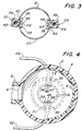
- the electro-static neutralizers D1 and D2 (mounted in injector tube B) and F1 and F2 (mounted in the lower portion of the elutriation column A) each comprise a longitudinally extending bar 36 of insulative material, such as polystyrene or polytetrafluroethylene, Teflon (registered trade mark), having a flanged portion 38 defining slots 40 which attach to the cylindrical wall of the injection tube 20 or correspondingly to that of the down tube 18 of the elutriation column.
- insulative material such as polystyrene or polytetrafluroethylene, Teflon (registered trade mark)
- the conductive metal injector tube 20 and the conductive metal down tube 18 of the elutriation column A act as spaced reference electrodes for the points 46 and 47 of the respective electro-static neutralizers D1-D2 and F1-F2 to enable AC ion emission from said points.
- Longitudinally spaced conductive needles 47 pass through complementary apertures in the elongated bars 36 of neutralizers D2 and F2 into engagement with the central conductor of cable 44.
- the needle electrodes 46 and 47 face one another.
- the neutralizers F1 and F2 are mounted in diametrically opposed disposition within the walls 18, the needle electrodes 47 project through the slot 48 of the corresponding bar 36 into the interior of the down tube 18 and face the pointed electrodes 46 thereof.
- the mode of operation of the prior art electro-static elimination system embodies a pair of diametrically opposed static neutralizers H1 and H2 oriented on the opposite walls of a metal tube 49 and whose discharge electrodes 46 and 47 are both connected to one side of an AC high voltage power supply G. That is, the high side of the transformer secondary 51 is connected to common lead 53 branching off to lines 55 and 57 coupled to the points 46 and 47 of each of the static neutralizers H1 and H2 while the low side of the transformer secondary is connected to ground.
- the metal tube 49 is also coupled to ground. It has been found that a slight excess of negative ions are produced by this system and a predominant negative charge is produced on particulate material passing through the tube 49.
- the opposed static neutralizers D1-D2 and F1-F2 of the present invention are coupled to the opposite sides of secondary coil 50 of the AC high voltage power supply G and the transformer secondary 50 itself is centre tapped to ground via lead 52.
- a positive half cycle of voltage imposed on the primary 54 of the power supply G will appear as a positive half cycle of voltage on cable 42 and points 46 while a negative half cycle of voltage is imposed on the points 47 via cable 44.
- a negative half cycle of voltage is applied to emitter points 46 via cable 42
- a positive half cycle of voltage is applied to points 47 by way of cable conductor 44.
- FIG 7 there is shown a test set up in which one ionizer, for example F1,is coupled to voltage V1 of phase A from one side of the secondary coil 50 by way of cable 42 while the other ionizer F2 arranged in diametrically opposing disposition is coupled to voltage V2 from phase B of the other side of the secondary coil via conductor 44.
- the tube 18 was allowed to float (no ground connection).
- the AC and DC voltage on the tube 18 was measured using a non-contact electrometer type field meter 60 adjacently spaced from the tube 18 by way of an sir space of about 1/4 inch distance (i.e. - designated by capacitance 62).
- the voltage on the wall of tube 18 with respect to ground provided one input 58 to the field meter 60 and field meter output was connected to an oscilloscope 64. This provided a very high impedance arrangement for measuring voltages on the tube 18.
- a negative ion imbalance is the result.
- This negative ion imbalance is due primarily to the fact that the negative corona onset voltage is lower than the positive corona onset but also because the difference in negative ion mobility plays a role in ion imbalance.
- the charge on the pellets was reduced to approximately -0.31 nC/g.
- the charge level was reduced only by a factor of about ten and the polarity of the charge reversed to become negative. This would indicate that where single-phase static neutralizers are employed (i.e. the same AC high voltage being applied to the emitter points at the same time) and the metal tub grounded (i.e. adjacent ground), that neutralization would occur but a low level of residual static charge would be deposited on the pellets due to imbalance of the air ionizers.
- Suitable air pressure gauges 70 and 72 on the face of the cleaning apparatus enable the operator to feed air at a pre-determined pressure from compressed air sources (not shown) to the compressed air conduits 22 and 24 in order to inject the dirty granules through the injection tube B and into the elutriation column A to provide a fluidized bed at the desired level.
- the vacuum applied to the tubular conduit 12 is monitored by vacuum gauge 74 to ensure that adequate vacuum level is maintained and assure complete collection of the lighter weight particulate.
Landscapes
- Elimination Of Static Electricity (AREA)
Applications Claiming Priority (2)
| Application Number | Priority Date | Filing Date | Title |
|---|---|---|---|
| US93081192A | 1992-08-17 | 1992-08-17 | |
| US930811 | 1992-08-17 |
Publications (3)
| Publication Number | Publication Date |
|---|---|
| EP0583924A2 true EP0583924A2 (fr) | 1994-02-23 |
| EP0583924A3 EP0583924A3 (fr) | 1994-10-19 |
| EP0583924B1 EP0583924B1 (fr) | 1998-05-27 |
Family
ID=25459808
Family Applications (1)
| Application Number | Title | Priority Date | Filing Date |
|---|---|---|---|
| EP19930306247 Expired - Lifetime EP0583924B1 (fr) | 1992-08-17 | 1993-08-06 | Dispositif d'élutriation et procédé pour nettoyer des granules |
Country Status (2)
| Country | Link |
|---|---|
| EP (1) | EP0583924B1 (fr) |
| DE (1) | DE69318774T2 (fr) |
Cited By (1)
| Publication number | Priority date | Publication date | Assignee | Title |
|---|---|---|---|---|
| EP0891820A3 (fr) * | 1997-07-16 | 2000-01-12 | Mann + Hummel ProTec GmbH | Séparateur pneumatique |
Families Citing this family (1)
| Publication number | Priority date | Publication date | Assignee | Title |
|---|---|---|---|---|
| TWI842050B (zh) * | 2022-08-11 | 2024-05-11 | 能資國際股份有限公司 | 外層地導電迴路架構的奈米碳管式軟x射線靜電消除裝置 |
Family Cites Families (5)
| Publication number | Priority date | Publication date | Assignee | Title |
|---|---|---|---|---|
| US2940592A (en) * | 1955-02-23 | 1960-06-14 | Union Carbide Corp | Method of and apparatus for powder elutriation |
| US3137806A (en) * | 1960-11-22 | 1964-06-16 | Simco Co Inc | Dustproof static eliminator |
| US3475652A (en) * | 1966-12-05 | 1969-10-28 | Simco Co Inc The | Dual phase static eliminator |
| US4046492A (en) * | 1976-01-21 | 1977-09-06 | Vortec Corporation | Air flow amplifier |
| US4299693A (en) * | 1980-04-30 | 1981-11-10 | Allied Industries | Separator |
-
1993
- 1993-08-06 DE DE1993618774 patent/DE69318774T2/de not_active Expired - Fee Related
- 1993-08-06 EP EP19930306247 patent/EP0583924B1/fr not_active Expired - Lifetime
Cited By (1)
| Publication number | Priority date | Publication date | Assignee | Title |
|---|---|---|---|---|
| EP0891820A3 (fr) * | 1997-07-16 | 2000-01-12 | Mann + Hummel ProTec GmbH | Séparateur pneumatique |
Also Published As
| Publication number | Publication date |
|---|---|
| DE69318774D1 (de) | 1998-07-02 |
| EP0583924A3 (fr) | 1994-10-19 |
| EP0583924B1 (fr) | 1998-05-27 |
| DE69318774T2 (de) | 1998-09-24 |
Similar Documents
| Publication | Publication Date | Title |
|---|---|---|
| US5289921A (en) | Elutriation apparatus and method for cleaning granules | |
| US3407930A (en) | Method and apparatus for the electrostatic sorting of granular materials | |
| Calin et al. | Tribocharging of granular plastic mixtures in view of electrostatic separation | |
| US20040226446A1 (en) | Grid type electrostatic separator/collector and method of using same | |
| KR100710697B1 (ko) | 가스 흐름으로부터 입자 및/또는 소적 형태의 물질을분리시키는 방법 및 장치 | |
| US3747299A (en) | Electrostatic precipitator | |
| GB1036604A (en) | High tension separation of materials | |
| Park et al. | Separation of covering plastics from particulate copper in cable wastes by induction electrostatic separation | |
| US5735403A (en) | Apparatus for removal of fine particles in material flow system | |
| US6789679B2 (en) | Method and apparatus for separating particles | |
| GB2130922A (en) | Electrostatic separation particulate materials | |
| US4305797A (en) | Material separation by dielectrophoresis | |
| US6034342A (en) | Process and apparatus for separating particles by use of triboelectrification | |
| GB2130921A (en) | Electrostatic separation of particulate materials | |
| EP0583924B1 (fr) | Dispositif d'élutriation et procédé pour nettoyer des granules | |
| JP5534800B2 (ja) | 選別装置 | |
| JP3512319B2 (ja) | プラスチック選別装置 | |
| JPS5742355A (en) | Electrostatic separator | |
| JPS59109262A (ja) | 粒状物の分離方法および装置 | |
| Achouri et al. | Tribo-electrostatic separation of two or more plastics contained in granular mixtures originating from WEEE | |
| KR0176069B1 (ko) | 싸이클론 마찰대전장치 | |
| GB1107574A (en) | Method and apparatus for the electrostatic sorting of granular materials | |
| ATE230307T1 (de) | Verfahren und vorrichtung zur elektrostatischer trennung eines bruchgutes | |
| EP0024867B1 (fr) | Appareil de détection de particules stagnantes | |
| Benaouda et al. | Insulating conveyor-belt-type electrostatic separator for triboelectrically-charged granular plastic wastes |
Legal Events
| Date | Code | Title | Description |
|---|---|---|---|
| PUAI | Public reference made under article 153(3) epc to a published international application that has entered the european phase |
Free format text: ORIGINAL CODE: 0009012 |
|
| AK | Designated contracting states |
Kind code of ref document: A2 Designated state(s): DE ES FR GB IT |
|
| PUAL | Search report despatched |
Free format text: ORIGINAL CODE: 0009013 |
|
| AK | Designated contracting states |
Kind code of ref document: A3 Designated state(s): DE ES FR GB IT |
|
| 17P | Request for examination filed |
Effective date: 19950331 |
|
| 17Q | First examination report despatched |
Effective date: 19970414 |
|
| GRAG | Despatch of communication of intention to grant |
Free format text: ORIGINAL CODE: EPIDOS AGRA |
|
| GRAG | Despatch of communication of intention to grant |
Free format text: ORIGINAL CODE: EPIDOS AGRA |
|
| GRAH | Despatch of communication of intention to grant a patent |
Free format text: ORIGINAL CODE: EPIDOS IGRA |
|
| GRAH | Despatch of communication of intention to grant a patent |
Free format text: ORIGINAL CODE: EPIDOS IGRA |
|
| GRAA | (expected) grant |
Free format text: ORIGINAL CODE: 0009210 |
|
| AK | Designated contracting states |
Kind code of ref document: B1 Designated state(s): DE ES FR GB IT |
|
| PG25 | Lapsed in a contracting state [announced via postgrant information from national office to epo] |
Ref country code: IT Free format text: LAPSE BECAUSE OF FAILURE TO SUBMIT A TRANSLATION OF THE DESCRIPTION OR TO PAY THE FEE WITHIN THE PRE;WARNING: LAPSES OF ITALIAN PATENTS WITH EFFECTIVE DATE BEFORE 2007 MAY HAVE OCCURRED AT ANY TIME BEFORE 2007. THE CORRECT EFFECTIVE DATE MAY BE DIFFERENT FROM THE ONE RECORDED.SCRIBED TIME-LIMIT Effective date: 19980527 Ref country code: FR Free format text: LAPSE BECAUSE OF FAILURE TO SUBMIT A TRANSLATION OF THE DESCRIPTION OR TO PAY THE FEE WITHIN THE PRESCRIBED TIME-LIMIT Effective date: 19980527 Ref country code: ES Free format text: THE PATENT HAS BEEN ANNULLED BY A DECISION OF A NATIONAL AUTHORITY Effective date: 19980527 |
|
| REF | Corresponds to: |
Ref document number: 69318774 Country of ref document: DE Date of ref document: 19980702 |
|
| EN | Fr: translation not filed | ||
| PLBE | No opposition filed within time limit |
Free format text: ORIGINAL CODE: 0009261 |
|
| STAA | Information on the status of an ep patent application or granted ep patent |
Free format text: STATUS: NO OPPOSITION FILED WITHIN TIME LIMIT |
|
| 26N | No opposition filed | ||
| PGFP | Annual fee paid to national office [announced via postgrant information from national office to epo] |
Ref country code: DE Payment date: 20010719 Year of fee payment: 9 |
|
| PGFP | Annual fee paid to national office [announced via postgrant information from national office to epo] |
Ref country code: GB Payment date: 20010720 Year of fee payment: 9 |
|
| REG | Reference to a national code |
Ref country code: GB Ref legal event code: IF02 |
|
| PG25 | Lapsed in a contracting state [announced via postgrant information from national office to epo] |
Ref country code: GB Free format text: LAPSE BECAUSE OF NON-PAYMENT OF DUE FEES Effective date: 20020806 |
|
| PG25 | Lapsed in a contracting state [announced via postgrant information from national office to epo] |
Ref country code: DE Free format text: LAPSE BECAUSE OF NON-PAYMENT OF DUE FEES Effective date: 20030301 |
|
| GBPC | Gb: european patent ceased through non-payment of renewal fee |
Effective date: 20020806 |