EP0584164B1 - Systeme comportant des prises de courant electriqueset des connecteurs - Google Patents
Systeme comportant des prises de courant electriqueset des connecteurs Download PDFInfo
- Publication number
- EP0584164B1 EP0584164B1 EP92910331A EP92910331A EP0584164B1 EP 0584164 B1 EP0584164 B1 EP 0584164B1 EP 92910331 A EP92910331 A EP 92910331A EP 92910331 A EP92910331 A EP 92910331A EP 0584164 B1 EP0584164 B1 EP 0584164B1
- Authority
- EP
- European Patent Office
- Prior art keywords
- outlet
- electrical
- adaptor
- type
- connector
- Prior art date
- Legal status (The legal status is an assumption and is not a legal conclusion. Google has not performed a legal analysis and makes no representation as to the accuracy of the status listed.)
- Expired - Lifetime
Links
Images



Classifications
-
- H—ELECTRICITY
- H02—GENERATION; CONVERSION OR DISTRIBUTION OF ELECTRIC POWER
- H02G—INSTALLATION OF ELECTRIC CABLES OR LINES, OR OF COMBINED OPTICAL AND ELECTRIC CABLES OR LINES
- H02G3/00—Installations of electric cables or lines or protective tubing therefor in or on buildings, equivalent structures or vehicles
-
- H—ELECTRICITY
- H01—ELECTRIC ELEMENTS
- H01R—ELECTRICALLY-CONDUCTIVE CONNECTIONS; STRUCTURAL ASSOCIATIONS OF A PLURALITY OF MUTUALLY-INSULATED ELECTRICAL CONNECTING ELEMENTS; COUPLING DEVICES; CURRENT COLLECTORS
- H01R25/00—Coupling parts adapted for simultaneous co-operation with two or more identical counterparts, e.g. for distributing energy to two or more circuits
- H01R25/16—Rails or bus-bars provided with a plurality of discrete connecting locations for counterparts
-
- H—ELECTRICITY
- H02—GENERATION; CONVERSION OR DISTRIBUTION OF ELECTRIC POWER
- H02B—BOARDS, SUBSTATIONS OR SWITCHING ARRANGEMENTS FOR THE SUPPLY OR DISTRIBUTION OF ELECTRIC POWER
- H02B1/00—Frameworks, boards, panels, desks, casings; Details of substations or switching arrangements
- H02B1/24—Circuit arrangements for boards or switchyards
Definitions
- the present invention relates to an electrical outlet system having electrical outlets intended for use primarily for electric lighting but which may be used for power outlets.
- Various systems are available for providing power outlets at several places along a length of a fitted linear supply device where the outlets may be located movably or semi-permanently.
- This device is formed as a trunking for mounting at dado height or skirting level in offices or light industrial buildings where it may be needed to rapidly rearrange the outlets.
- Within the trunking is a triple busbar arrangement into which outlet sockets can be plugged anywhere along the busbar.
- busbar systems are available for installation in ceiling voids.
- track lighting systems where lighting outlets can be clipped into the track at any desired point see EP-A-0 299811.
- a system of electrical outlets and connectors comprising a plurality of electrical outlets which are interconnected electrically, each outlet having a plurality of contacts for a power supply characterised in that a first type and a second type of outlet connector are provided and in that each outlet has a switching means permanently provided to normally electrically connect two contacts of the outlet, the switching means being operable by the connection or disconnection of the first type of outlet connector to or from the outlet whilst the connection or disconnection of the second type of outlet connector to or from the outlet will leave the electrical connection of the two contacts intact.
- the switching means enables the transfer of electrical control from the feed to the outgoing power supply or from the outgoing power supply to the component supplied, to a location within "reach" of the switching means.
- the outlets are preferably mounted on linear support structure the outlets being interconnected electrically to form a limited bar.
- This enables an arrangement to be constructed with outlet connectors of the first type acting as control switches and outlet connectors of the second type acting as lighting or power outlets.
- the control switches separate the bar into sections and take "command" of a section preferably in one direction of the bar so as to switch lights plugged in that direction until the next control switch or end of the bar.
- Adaptors can be provided which comprise means for connection to the system and having electrical switching means so as to permit the carrying out of logical operations between any one or more electrical components associated with the system.
- the adaptor can be in the form of an extension with a simple switch control, dimmer, timer or may permit the carrying out of logical operations between an electrical signal present on any connection and an electrical, mechanical, optical or other input to the system.
- separately powered parallel bars may be provided and switch control jumped from bar to bar with if necessary interface isolation between switch control jumpers.
- power supplies can be of a different level or characteristic whilst switching can still be effected between bars.
- Figure 1 shows an outlet system according to the invention with three sockets, one free and the others having a simple control switch and a light respectively.
- Figure 2 shows an outlet system as in Fig. 1 but with extension sockets in each of the three sockets.
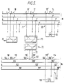
- Figure 3 shows an outlet system as in Fig. 1 but with a simple control switch, a two way control switch and a light the whole arranged for two way switching.
- Figure 4 shows an outlet system according to the invention having a pair of busbars with arrangements to transfer control from one bar to another.
- Figure 5 shows an outlet system similar to that shown in Figure 4 but in which the arrangements to transfer control include means for duplication on the second bar of a varying or modulated supply that exists on the first busbar.
- Figure 6 shows an outlet system similar to that of Fig. 1 with an adaptor introducing a control box.
- Figure 7 shows an adaptor inserted in an outlet of the system similar to that of Fig. 1 with a control box in series with an extension socket with the possibility of connecting further control devices, and
- Figure 8 shows an adaptor inserted as Fig. 7 but without an extension socket.
- the system comprises a linear quadruple busbar arrangement 16, busbar S being a switched line, busbar L being connected to a line supply, busbar N being the neutral line and connected to neutral of the supply, whilst E represents the earth line.
- Socket positions are indicated at 10, 12 and 14. These are spaced at convenient even distances along the quadruple busbar 16. At each position there are five connecting positions, namely 1 on bar E, 2 on bar N, 3 on bar L and 4 and 5 on bar or line S either side of switch 18 which makes or breaks line S.
- Switching device 20 has its own switch 22 connecting through lines 24 and 25 to positions 5 and 3 respectively. Switching device 20 also has spare lines 26 and 27. If required a locator lamp 28 can be connected across lines 26 and 25.
- Outlet 12 is not used in the Figure 1 arrangement switch 18' is left in its normal make condition across positions 4' and 5'.
- Outlet 14 is used to receive a second type of outlet connector shown as a lighting outlet connector 30.
- This second type of connector does not operate switch 18" between 4" and 5" but connects through lines 31, 32, 33 and 34 to positions 4", 3", 2" and 1" respectively. Only lines 31 and 33 are used to power lamp 35.
- the system is thus designed for uni-directional control although it could in theory be adapted to bi-directional control.
- the advantage of uni-directional control by switching line S is that installation is easy to comprehend.
- linear quadruple busbars as described above are conveniently installed in a building so as to be parallel with adjacent quadruple busbars arranged to have their directional control in opposite directions. That is the quadruple busbars are alternatively streamed in opposed directions. Whilst busbars are described above as quadruple they can incorporate furthers bar or lines for three phase power supplies and adjacent bars can be fed with differing phased or charactered power supplies whilst in effect having a common switching line which as will be described with reference to Fig. 5 may incorporate interfaced isolation.
- the arrangement in Figure 3 is such as to provide two way switching into unoccupied socket 12 of the Figure 1 arrangement, a two way switch device 50 of the first type of connector is plugged in. This opens socket switch 18' and transfers control of line S to a manual two way switch 51, device 50 also incorporating a change over relay 52 having a solenoid 53 controlling switch 54. Switches 22 and 51 both control power to downstream lamp 35 of outlet connector 30.
- FIG. 4 shows how adjacent busbars 16 and 116 can have their switching lines S and S' interconnected by jumper 60 so as to control lighting outlet connector 30 on busbar 16 and connector 130 on busbar 116 by switching device 20 on busbar 16.
- Jumper 60 has a first end plug 61 of the second type plugged into socket 12 of busbar 16 which does not open switch 18' and a second end plug 62 of the first type plugged into socket 112 of busbar 116 such that switch 118' in line S' is broken between points 104' and 105'.
- Jumper 60 also has a relay 63 comprising a solenoid 64 and switch 65.
- the power to operate lamp 35 comes solely from lines N and L via a switched (i.e. powered) portion of line S of busbar 16 whilst the power to operate lamp 135 comes solely from lines N' and L' of busbar 116 via a portion of line S' switched (i.e. powered) by relay switch 65.
- Busbars 16 and 116 are both shown streaming the same way but are preferably streamed in opposite directions. Both busbars 16 and 116 are individually powered and can be powered and earthed at either end of lines L, N, E, L', N' and E'. Making switch 22 causes lamp 35 and solenoid 64 to be powered and so powering lamp 135.
- a complex jumper 70 and control or switching device 20' is provided.
- Device 20' is for example a dimmer switch which modulates or drops the power supply to lamp 35.
- jumper 70 plugged by its plugs 71 and 72 into sockets 12 and 112 (as in Fig. 4), has an isolating interface relay device 73 which detects the modified supply across points 4' and 2' of bar 16 and relays this to points 105' and 103' on bar 116. Both lamps 35 and 135 are therefore similarly controlled by device 20'.
- Fig. 6 and adaptor 80 is plugged into busbar 16 across lines S, L, N and E having switching means in the adaptor 80 such as a residual circuit breaker so as to permit the carrying out of logical operations between any one or more components 81 such as lighting or power devices associated with the system.
- an adaptor with a first type outlet connector 83 (or plug) is plugged into outlet socket 10.
- the adaptor has an outlet 201-205 and electrical switching means 84 in the control box between the outlet 201-205 and connector 83 so as to permit the carrying out of logical operations including AND, OR and XOR between electrical signals present upon the connector or outlet or any one or more components 81.
- Switch 18 in line S is broken by insertion of connector 83 into the busbar 16.
- an adaptor 86 with a varied first type outlet connector 87 is plugged into outlet socket 10.
- Connector 87 may or may not operate switch 18 in line S of busbar 16 depending on the operation of adaptor 86 by control box 88 and switching means 89.
- the connector 87 is effectively of the first or second type since it may or may not open switch 18.
- the adaptor 86 therefore has at least one of the connectors and has electrical switching means 89 interposed between connections to, or point 5 and 4 in the system so as to permit the carrying out of logical operations between an electrical signal present on any connection and an electrical, mechanical, optical or other input to the system via switching means 89.
- the system has outlets and connectors such that when they are connected to one of the outlets the functionality of that outlet may be jumped either to a second outlet along the busbar or from busbar to adjacent busbar and if desired to further busbars.
- the present invention provides a system particularly useful for large office areas where the busbars 16, 116 and so on are fixed either directly to the ceiling or in a ceiling space with downward extensions as described with reference to Figure 2.
- the outlets on the busbars can be controlled by any suitable means plugged into the same or different such busbars and this switching can be arranged to control with components readily plugged into the outlets any number of other system outlets in blocks or lines, with the option of even leaving a single light on as an emergency light.
- the arrangement of outlets and controls of the system can be quickly rearranged. Control can always be arranged wherever it is most convenient.
Landscapes
- Engineering & Computer Science (AREA)
- Architecture (AREA)
- Civil Engineering (AREA)
- Structural Engineering (AREA)
- Power Engineering (AREA)
- Details Of Connecting Devices For Male And Female Coupling (AREA)
- Circuit Arrangement For Electric Light Sources In General (AREA)
- Connector Housings Or Holding Contact Members (AREA)
- Coupling Device And Connection With Printed Circuit (AREA)
- Connection Or Junction Boxes (AREA)
Abstract
Claims (8)
- Système comportant des prises de courant électrique et des connecteurs, comprenant plusieurs prises (10,12...) de courant électrique reliées électriquement les unes aux autres, chaque prise ayant plusieurs contacts (2,2'.., 3,3'.., 4,4'.., 5,5'..) pour une alimentation en courant, caractérisé en ce qu'un premier type (20) et un second type (30) de connecteur de prise sont présents et en ce que chaque prise a un moyen de commutation (18,18'..) disposé de manière permanente pour, dans des conditions normales, connecter électriquement deux contacts (4,5) de la prise, le moyen de commutation étant actionnable par la connexion ou la déconnexion du premier type de connecteur de prise à ou d'avec la prise, tandis que la connexion ou la déconnexion du second type de connecteur de prise à ou d'avec la prise laisse inchangée la connexion électrique des deux contacts.
- Système selon la revendication 1, dans lequel les prises sont montées sur une structure de support linéaire (16).
- Système selon la revendication 1 ou 2, dans lequel un adaptateur (80) est présent, l'adaptateur comportant un moyen pour la connexion avec le système et ayant un moyen de commutation électrique de façon à permettre l'exécution d'opérations logiques entre n'importe lesquels ou plusieurs des composants électriques (81) associés au système.
- Système selon l'une quelconque des revendications 1 à 3, dans lequel un adaptateur est présent, l'adaptateur comprenant un connecteur (83) de prise dudit premier type et une prise (201-205) et ayant un moyen de commutation électrique (84) intercalé entre ledit premier type de connecteur de prise et ladite prise de façon à permettre l'exécution d'opérations logiques comprenant des opérations ET, OU et OU EXCLUSIF entre des signaux électriques présents dans le connecteur de prise ou la prise.
- Système selon l'une quelconque des revendications précédentes, dans lequel un adaptateur (86) est présent, l'adaptateur comportant un des connecteurs (87) de prise et ayant un moyen de commutation électrique (89) intercalé entre des connexions au système de façon à permettre l'exécution d'opérations logiques entre un signal électrique présent à l'un quelconque desdits contacts et une entrée électrique, mécanique, optique ou autre du système.
- Système selon l'une quelconque des revendications précédentes, dans lequel un adaptateur pouvant être connecté à une prise est présent, l'adaptateur comprenant en outre un mécanisme de synchronisation.
- Système selon l'une quelconque des revendications précédentes dans lequel un adaptateur est présent, l'adaptateur comprenant en outre un moyen (20') de variation ou de modulation d'une alimentation en courant d'un ou plusieurs desdits contacts.
- Système selon l'une quelconque des revendications précédentes, comportant une autre prise (112) et un autre connecteur (72) de prise dudit premier type connectés électriquement l'un à l'autre, ledit autre connecteur de prise et ladite autre prise étant agencés de façon que lorsqu'ils sont connectés à une prise la fonctionnalité de cette prise est transmise à ladite autre prise.
Applications Claiming Priority (3)
| Application Number | Priority Date | Filing Date | Title |
|---|---|---|---|
| GB9110813 | 1991-05-17 | ||
| GB9110813A GB2255865B (en) | 1991-05-17 | 1991-05-17 | An electrical outlet system |
| PCT/GB1992/000870 WO1992021172A1 (fr) | 1991-05-17 | 1992-05-14 | Systeme comportant des prises de courant electriques |
Publications (2)
| Publication Number | Publication Date |
|---|---|
| EP0584164A1 EP0584164A1 (fr) | 1994-03-02 |
| EP0584164B1 true EP0584164B1 (fr) | 1996-03-20 |
Family
ID=10695253
Family Applications (1)
| Application Number | Title | Priority Date | Filing Date |
|---|---|---|---|
| EP92910331A Expired - Lifetime EP0584164B1 (fr) | 1991-05-17 | 1992-05-14 | Systeme comportant des prises de courant electriqueset des connecteurs |
Country Status (9)
| Country | Link |
|---|---|
| EP (1) | EP0584164B1 (fr) |
| JP (1) | JPH07501416A (fr) |
| AU (1) | AU655985B2 (fr) |
| CA (1) | CA2109196A1 (fr) |
| DE (1) | DE69209289D1 (fr) |
| FI (1) | FI935080A7 (fr) |
| GB (1) | GB2255865B (fr) |
| NO (1) | NO934150L (fr) |
| WO (1) | WO1992021172A1 (fr) |
Families Citing this family (6)
| Publication number | Priority date | Publication date | Assignee | Title |
|---|---|---|---|---|
| GB9304195D0 (en) * | 1993-03-02 | 1993-04-21 | Mk Electric Ltd | An electrical control and connection system |
| JP3186938B2 (ja) * | 1994-12-12 | 2001-07-11 | 富士通株式会社 | 外部電源オン/オフ制御システム |
| US7269034B2 (en) | 1997-01-24 | 2007-09-11 | Synqor, Inc. | High efficiency power converter |
| EP0954899A2 (fr) | 1997-01-24 | 1999-11-10 | Fische, LLC | Convertisseur de puissance a haute efficacite |
| US10199950B1 (en) | 2013-07-02 | 2019-02-05 | Vlt, Inc. | Power distribution architecture with series-connected bus converter |
| WO2018051381A1 (fr) * | 2016-09-19 | 2018-03-22 | Alosys Communications S.R.L. | Système d'éclairage conçu pour alimenter au moins un bloc d'alimentation pouvant alimenter des dispositifs ou des systèmes électroniques |
Family Cites Families (10)
| Publication number | Priority date | Publication date | Assignee | Title |
|---|---|---|---|---|
| GB548373A (en) * | 1941-06-04 | 1941-10-07 | Louis George Morten | Electricity conductor unit |
| DE1116296B (de) * | 1960-03-17 | 1961-11-02 | Krone Gmbh | Schaltstreifen, insbesondere Schalt- und Trennloetoesenstreifen |
| CH377419A (fr) * | 1961-11-03 | 1964-05-15 | Burkhard Charles | Procédé de montage d'une installation de distribution d'énergie électrique dans un immeuble et installation obtenue par ce procédé |
| FR1386504A (fr) * | 1963-12-13 | 1965-01-22 | élément de canalisation électrique et ses organes de raccordement | |
| US4059773A (en) * | 1976-07-15 | 1977-11-22 | Nash Charles A | Switch controlled power receptacle system |
| FR2488743A1 (fr) * | 1980-08-13 | 1982-02-19 | Quercy Equip Elect | Systeme de cablage electrique, boite de raccordement et dispositif de connexion s'y rapportant |
| US4759729A (en) * | 1984-11-06 | 1988-07-26 | Adc Telecommunications, Inc. | Electrical connector apparatus |
| US4591777A (en) * | 1984-12-17 | 1986-05-27 | Solid State Chargers Research & Development | Multi-station modular charging system for cordless tools and appliances |
| GB8524325D0 (en) * | 1985-10-02 | 1985-11-06 | Ranton & Co Ltd | Electrical accessories |
| FR2618026B1 (fr) * | 1987-07-08 | 1989-11-17 | Telemecanique Electrique | Canalisation electrique prefabriquee pour la realisation de circuits de distribution electrique pouvant incorporer des zones de distribution commandables a conformations variables |
-
1991
- 1991-05-17 GB GB9110813A patent/GB2255865B/en not_active Expired - Fee Related
-
1992
- 1992-05-14 DE DE69209289T patent/DE69209289D1/de not_active Expired - Lifetime
- 1992-05-14 FI FI935080A patent/FI935080A7/fi unknown
- 1992-05-14 EP EP92910331A patent/EP0584164B1/fr not_active Expired - Lifetime
- 1992-05-14 JP JP4510483A patent/JPH07501416A/ja active Pending
- 1992-05-14 AU AU17876/92A patent/AU655985B2/en not_active Ceased
- 1992-05-14 CA CA002109196A patent/CA2109196A1/fr not_active Abandoned
- 1992-05-14 WO PCT/GB1992/000870 patent/WO1992021172A1/fr not_active Ceased
-
1993
- 1993-11-16 NO NO934150A patent/NO934150L/no unknown
Also Published As
| Publication number | Publication date |
|---|---|
| CA2109196A1 (fr) | 1992-11-18 |
| FI935080A0 (fi) | 1993-11-16 |
| FI935080L (fi) | 1993-11-16 |
| GB2255865A (en) | 1992-11-18 |
| GB2255865B (en) | 1995-02-15 |
| WO1992021172A1 (fr) | 1992-11-26 |
| NO934150L (no) | 1993-11-17 |
| AU655985B2 (en) | 1995-01-19 |
| FI935080A7 (fi) | 1993-11-16 |
| AU1787692A (en) | 1992-12-30 |
| NO934150D0 (no) | 1993-11-16 |
| GB9110813D0 (en) | 1991-07-10 |
| JPH07501416A (ja) | 1995-02-09 |
| EP0584164A1 (fr) | 1994-03-02 |
| DE69209289D1 (de) | 1996-04-25 |
Similar Documents
| Publication | Publication Date | Title |
|---|---|---|
| AU2006326844B2 (en) | Power distribution system with individually isolatable functional zones | |
| DE3475589D1 (en) | Power supply system | |
| US20030194914A1 (en) | Modular plug connector | |
| JPH08211910A (ja) | 統合化フィールドバス接続部を有するモジュール形制御装置 | |
| US5071356A (en) | Modular terminal arrangement | |
| US7990082B2 (en) | Methods and systems for operating and controlling theatrical lighting | |
| EP0584164B1 (fr) | Systeme comportant des prises de courant electriqueset des connecteurs | |
| US4689493A (en) | Centralized switching circuit for building electrical network | |
| US5326933A (en) | Electrical installation system | |
| US6320732B1 (en) | Electrical power distribution control system with dual voltage sources | |
| US4578593A (en) | Two-way electrical control module for a lamp outlet | |
| GB2275835A (en) | Power distribution system; Lighting control system | |
| EP0950278B1 (fr) | Circuit pour alimenter selectivement des unites electriques | |
| US7204696B1 (en) | Duplex receptacle | |
| CN1913266B (zh) | 使用具有保护连接器的电缆的模块化配电设备和方法 | |
| EP3089552B1 (fr) | Distribution de puissance basse tension à courant continu et système pour un réseau électrique | |
| AU709346B2 (en) | Modular electrical power distribution and switching system | |
| EP0112311B1 (fr) | Une méthode pour la réalisation d'une fonction de relais temporisé et un dispositif pour l'utilisation de la méthode | |
| AU2013100509A4 (en) | Easy connect power control module | |
| AU731006B2 (en) | EIB device for insertion in an installation box | |
| JP3425087B2 (ja) | 配線システム | |
| EP0596257A3 (fr) | Prise pour composant. | |
| AU3394099A (en) | Modular electrical power distribution and switching system and connection module therefor | |
| EP3516934B1 (fr) | Système d'éclairage conçu pour alimenter au moins un bloc d'alimentation pouvant alimenter des dispositifs ou des systèmes électroniques | |
| JPH07274327A (ja) | 補助母線付固体絶縁開閉装置 |
Legal Events
| Date | Code | Title | Description |
|---|---|---|---|
| PUAI | Public reference made under article 153(3) epc to a published international application that has entered the european phase |
Free format text: ORIGINAL CODE: 0009012 |
|
| 17P | Request for examination filed |
Effective date: 19930913 |
|
| AK | Designated contracting states |
Kind code of ref document: A1 Designated state(s): DE FR IT NL SE |
|
| RAP1 | Party data changed (applicant data changed or rights of an application transferred) |
Owner name: CARADON MK ELECTRIC LIMITED |
|
| 17Q | First examination report despatched |
Effective date: 19950511 |
|
| GRAA | (expected) grant |
Free format text: ORIGINAL CODE: 0009210 |
|
| AK | Designated contracting states |
Kind code of ref document: B1 Designated state(s): DE FR IT NL SE |
|
| PG25 | Lapsed in a contracting state [announced via postgrant information from national office to epo] |
Ref country code: NL Free format text: LAPSE BECAUSE OF FAILURE TO SUBMIT A TRANSLATION OF THE DESCRIPTION OR TO PAY THE FEE WITHIN THE PRESCRIBED TIME-LIMIT Effective date: 19960320 Ref country code: IT Free format text: LAPSE BECAUSE OF FAILURE TO SUBMIT A TRANSLATION OF THE DESCRIPTION OR TO PAY THE FEE WITHIN THE PRE;WARNING: LAPSES OF ITALIAN PATENTS WITH EFFECTIVE DATE BEFORE 2007 MAY HAVE OCCURRED AT ANY TIME BEFORE 2007. THE CORRECT EFFECTIVE DATE MAY BE DIFFERENT FROM THE ONE RECORDED.SCRIBED TIME-LIMIT Effective date: 19960320 |
|
| REF | Corresponds to: |
Ref document number: 69209289 Country of ref document: DE Date of ref document: 19960425 |
|
| PG25 | Lapsed in a contracting state [announced via postgrant information from national office to epo] |
Ref country code: SE Effective date: 19960620 |
|
| ET | Fr: translation filed | ||
| PG25 | Lapsed in a contracting state [announced via postgrant information from national office to epo] |
Ref country code: DE Effective date: 19960621 |
|
| NLV1 | Nl: lapsed or annulled due to failure to fulfill the requirements of art. 29p and 29m of the patents act | ||
| PLBE | No opposition filed within time limit |
Free format text: ORIGINAL CODE: 0009261 |
|
| STAA | Information on the status of an ep patent application or granted ep patent |
Free format text: STATUS: NO OPPOSITION FILED WITHIN TIME LIMIT |
|
| 26N | No opposition filed | ||
| PGFP | Annual fee paid to national office [announced via postgrant information from national office to epo] |
Ref country code: FR Payment date: 20010516 Year of fee payment: 10 |
|
| PG25 | Lapsed in a contracting state [announced via postgrant information from national office to epo] |
Ref country code: FR Free format text: LAPSE BECAUSE OF NON-PAYMENT OF DUE FEES Effective date: 20030131 |
|
| REG | Reference to a national code |
Ref country code: FR Ref legal event code: ST |