EP0584353B1 - Verformbarer spiegel und korrespondierende lasereinrichtung - Google Patents
Verformbarer spiegel und korrespondierende lasereinrichtung Download PDFInfo
- Publication number
- EP0584353B1 EP0584353B1 EP93918755A EP93918755A EP0584353B1 EP 0584353 B1 EP0584353 B1 EP 0584353B1 EP 93918755 A EP93918755 A EP 93918755A EP 93918755 A EP93918755 A EP 93918755A EP 0584353 B1 EP0584353 B1 EP 0584353B1
- Authority
- EP
- European Patent Office
- Prior art keywords
- lamellas
- deformable mirror
- mirror according
- case
- journal
- Prior art date
- Legal status (The legal status is an assumption and is not a legal conclusion. Google has not performed a legal analysis and makes no representation as to the accuracy of the status listed.)
- Expired - Lifetime
Links
- 238000009826 distribution Methods 0.000 claims abstract description 10
- 230000007246 mechanism Effects 0.000 claims abstract description 9
- 241000446313 Lamella Species 0.000 claims description 21
- 238000009434 installation Methods 0.000 claims description 4
- 238000001816 cooling Methods 0.000 claims description 3
- 230000001419 dependent effect Effects 0.000 claims 2
- 238000006073 displacement reaction Methods 0.000 claims 1
- 238000005452 bending Methods 0.000 abstract description 4
- 238000007669 thermal treatment Methods 0.000 abstract 1
- 238000010438 heat treatment Methods 0.000 description 3
- 230000001788 irregular Effects 0.000 description 2
- 239000012528 membrane Substances 0.000 description 2
- 230000003287 optical effect Effects 0.000 description 2
- 125000006850 spacer group Chemical group 0.000 description 2
- 238000004381 surface treatment Methods 0.000 description 2
- 241001282135 Poromitra oscitans Species 0.000 description 1
- 206010048232 Yawning Diseases 0.000 description 1
- 238000010521 absorption reaction Methods 0.000 description 1
- 239000000498 cooling water Substances 0.000 description 1
- 230000008878 coupling Effects 0.000 description 1
- 238000010168 coupling process Methods 0.000 description 1
- 238000005859 coupling reaction Methods 0.000 description 1
- 238000010586 diagram Methods 0.000 description 1
- 230000000694 effects Effects 0.000 description 1
- 230000000717 retained effect Effects 0.000 description 1
- 238000010079 rubber tapping Methods 0.000 description 1
- 238000011282 treatment Methods 0.000 description 1
- 238000009827 uniform distribution Methods 0.000 description 1
- 238000011144 upstream manufacturing Methods 0.000 description 1
Images


Classifications
-
- B—PERFORMING OPERATIONS; TRANSPORTING
- B23—MACHINE TOOLS; METAL-WORKING NOT OTHERWISE PROVIDED FOR
- B23K—SOLDERING OR UNSOLDERING; WELDING; CLADDING OR PLATING BY SOLDERING OR WELDING; CUTTING BY APPLYING HEAT LOCALLY, e.g. FLAME CUTTING; WORKING BY LASER BEAM
- B23K26/00—Working by laser beam, e.g. welding, cutting or boring
- B23K26/02—Positioning or observing the workpiece, e.g. with respect to the point of impact; Aligning, aiming or focusing the laser beam
- B23K26/06—Shaping the laser beam, e.g. by masks or multi-focusing
- B23K26/073—Shaping the laser spot
- B23K26/0732—Shaping the laser spot into a rectangular shape
-
- G—PHYSICS
- G02—OPTICS
- G02B—OPTICAL ELEMENTS, SYSTEMS OR APPARATUS
- G02B26/00—Optical devices or arrangements for the control of light using movable or deformable optical elements
- G02B26/08—Optical devices or arrangements for the control of light using movable or deformable optical elements for controlling the direction of light
- G02B26/0816—Optical devices or arrangements for the control of light using movable or deformable optical elements for controlling the direction of light by means of one or more reflecting elements
- G02B26/0833—Optical devices or arrangements for the control of light using movable or deformable optical elements for controlling the direction of light by means of one or more reflecting elements the reflecting element being a micromechanical device, e.g. a MEMS mirror, DMD
-
- G—PHYSICS
- G02—OPTICS
- G02B—OPTICAL ELEMENTS, SYSTEMS OR APPARATUS
- G02B26/00—Optical devices or arrangements for the control of light using movable or deformable optical elements
- G02B26/08—Optical devices or arrangements for the control of light using movable or deformable optical elements for controlling the direction of light
- G02B26/0816—Optical devices or arrangements for the control of light using movable or deformable optical elements for controlling the direction of light by means of one or more reflecting elements
- G02B26/0833—Optical devices or arrangements for the control of light using movable or deformable optical elements for controlling the direction of light by means of one or more reflecting elements the reflecting element being a micromechanical device, e.g. a MEMS mirror, DMD
- G02B26/0866—Optical devices or arrangements for the control of light using movable or deformable optical elements for controlling the direction of light by means of one or more reflecting elements the reflecting element being a micromechanical device, e.g. a MEMS mirror, DMD the reflecting means being moved or deformed by thermal means
Definitions
- the invention relates to a deformable mirror which can in particular be used in a laser installation.
- Lasers emit beams whose energy is not uniform over the section.
- This energy distribution generally has a symmetry of revolution and is in the form of a succession of rings of different energies.
- a particular case of this distribution can be a normal law.
- the disadvantage of such a situation appears in particular when the laser is used to make a surface treatment on a part, since the heating of the surface is irregular, as is the treatment obtained.
- the mirror consists of a deformable membrane stretched over a housing, the bottom of which is provided with support pieces of adjustable height, each reaching a particular point of the membrane.
- each of the supports can in particular provide a constant curvature for all the sections of the mirror arranged in a direction - which we will call longitudinal - in order to make the beam converge to control the width of the focused spot, and an irregular curvature on the perpendicular sections - in a transverse direction - so that the concavity of the mirror is maximum at the periphery and minimal in the center, where the mirror can also be convex, in order to disperse the light intensity in the center of the beam.
- This arrangement provides a light spot of rectangular shape and where the energy is uniformly distributed. It is obviously possible to obtain other forms of focusing of the beam as required.
- Such deformable mirror devices take a long time to adjust because the support parts are numerous and the adjustment of each has repercussions both on a width adjustment curvature and on an intensity adjustment curvature, that is to say - say that there is a coupling between the two settings.
- the fact of combining several mirrors causes an additional attenuation of the beam caused by the absorption of the mirrors (of the order of 2% per mirror).
- the laser powers used during surface treatments are high (greater than or equal to 5 kW), which requires cooling systems for all the components used in the optical system.
- the essential object of the invention is to simplify the adjustments of the deformations of a single mirror and that we submit to different curvatures in two perpendicular orientations to adjust in particular the width of a focused spot and the distribution of energy. along the length of the spot.
- the new and characteristic combination of the invention is a row of rectangular slats with light reflecting faces and juxtaposed by their long sides or sides in length, that is to say without significant yawning through which incident light would be lost.
- the slats are fixed to trunnions rotating in a housing and oriented along the length of the slats, and orientation mechanisms for turning the trunnions exist.
- Means for bending the slats around axes oriented along their width are added if it is desired to modify the curvature of the slats at will, which is then chosen to be elastic. Otherwise, we can be content rigid slats with cylindrical reflecting face.
- This arrangement allows complete decoupling between the curvature of the slats and the orientation of the slats according to a rotation perpendicular to the plane of curvature.
- the curvature of a lamella is difficult to adjust with precision as long as one wants to obtain deformed surfaces of complex shape, one preferably associates the curvature, adjustable or not, of the lamellae with the focusing in width, and the orientation of the slats then allows energy to be distributed along the focused spot.
- an orientation can be adjusted with great precision and the lamellae can be without numerous disadvantages, very different and complex distributions can be obtained if desired, or else great precision if one is interested in a uniform distribution.
- each pin is extended by a bar behind the reflecting face of one of the strips and the means for bending the strips consist of screw systems engaged on the strips and the strips to modify their spacings.
- a particularly simple arrangement consists in using a single screw system on the center of said strip, which is supported on the bar by its longitudinal ends.
- the slats are all controlled simultaneously and at a uniform curvature.
- Each pin is then composed of two separate parts and fixed respectively to a longitudinal end of one of the strips, the housing comprising two parts rotating one on the other. around an axis oriented along the width of the slats under the action of a curvature mechanism, one part of each pin turning in one of the housing parts, the other part of each pin turning in the other part of the housing.
- each orientation mechanism is arranged so as to impose rotations opposite to a respective pair of lamellae arranged symmetrically with respect to a median line, oriented longitudinally, of the mirror, because as the beam has a distribution of symmetrical energy and that one normally seeks to obtain a symmetrical distribution of the light energy on the focused spot, the mirror must be deformed symmetrically around the midline.
- the slats are juxtaposed with depth offsets so that they overlap over part of their width, the diffractions on the edges of the slats are reduced.
- the invention also relates to a laser and deformable mirror installation, the laser beam and the mirror being arranged so as to focus the beam on a rectangular portion of a surface to be treated, the width of said portion depending on the curvature of the strips and the length of said portion, as well as the distribution of the energy of the beam along said portion, depending on the orientation of the strips.
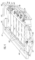
- FIG. 1 to 3 comprises a single housing 1 composed of two parallel and opposite flanges 2 and 3 connected by spacers 4.
- Each flange 2 and 3 carries a row of pins, respectively 5 and 6 and each pin 5 is associated with a pin 6 located in extension on the same axis by a bar 7 which connects them.
- the bar 7 is curved so that the reflecting face 8 of a rectangular and planar strip 9 has its center disposed on the axis of rotation of the pins 5 and 6. It can be seen in FIG. 2 that the strips 9 are rectangles long enough and almost joined by their long sides to form an almost continuous mirror surface.
- the longitudinal ends of the strips 9 are placed in simple support on rollers 10 and 11 respectively close to the pins 5 and 6 and glued to the bar 7, and a threaded rod 12 is fixed to the center of each strip 9, on its opposite rear face to the reflecting face 8.
- the threaded rod 12 has a length sufficient to pass through a bore 13 of the bar 7 and protrude on the other side.
- the nut 14 touches the bar 7, and if we continue the screwing, a curvature of the strip 9 is imposed which makes its reflecting face 8 concave.
- the bar 7 has in fact a very high rigidity with respect to the strip 9.
- a flexible jacket 15, made of rubber for example is bonded to the rear face of the strip 9 and traversed by cooling water thanks to a supply duct 16 and a discharge duct 17 placed on opposite ends of the jacket 15, not far from the rollers 10 and 12.
- Each pin 5 is provided with a lever 18 outside of the flange 2 and which moves at a constant distance from the latter when the pin 5 rotates. It is the lever 18 which controls the rotation of the pin 5 to which it is rigidly connected by means of conical head screws 19 engaged in threads of longitudinal orientation of the flange 2. It can be seen in FIG. 2 that the rotation of the screws with conical head 19 displaces levers 18, which touch the conical face of the heads, and in FIG. 3 that each conical head screw 19 is associated with two identical levers 18 and which control pins 5 and lamellae 9 located symmetrically with respect to to a longitudinal center line 20 of the mirror.
- the slats 9 are stepped in depth and are only approximately contiguous, because one of the edges 21 of each covers the edge 22 adjacent to its neighbor set back. The edges 22 are therefore not reached by the rays of the light beam F emitted towards the mirror, which reduces the inevitable diffractions at these places and which disturb the quality of the focusing.
- the housing 31 is here composed of a frame 32 carrying a simple bar 33 and a support bar 34.
- the bars 33 and 34 rotate one relative to the another around respective axes 35 and 36 located transversely relative to the lamellae, here again referenced by 9.
- Each of the axes 35 and 36 is terminated by a lever 37 or 38 whose free end passes within reach of the tip of a pressure screw 39 engaged in a tapping of the frame 32. It can be seen that the position adjustments of the screw 39 push the levers 37 and 38 more or less and cause the axes 35 and 36 and the bars 33 and 34 to tilt.
- Each of the bars 33 and 34 carries a row of split pins, respectively 40 and 41; the ends of each strip 9 are engaged in the slots of a pair of split trunnions 40 and 41 each belonging to one of the bars 33 and 34, so that the rotation of the latter causes uniform bending or curvature of the strips 9.
- the orientation of the slats 9 is caused by a device similar to the previous one and composed of levers 18 and conical head screws 19 which are engaged in the support bar 34, the levers 18 rotating the split trunnions 41.
- the trunnions 5, 6, 40 and 41 which are therefore free to rotate in the flanges 2 and 3 and the bars 33 and 34 are retained against sliding by a conventional means such as elastic rings serving as an axial stop.
- a conventional means such as elastic rings serving as an axial stop.
- the same assembly can be adopted for the axes 35 and 36.
- the slats 9 are prevented from sliding from the slots of the pins 40 and 41 by fixing them with pins or means similar to these pins 40 and 41.
- torsion springs 42 engaged around the pins 41 hold the levers 18 against the conical head screws 19.
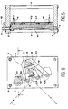
- the strip 49 of FIG. 5 can be used in place of one of the strips 9 on the device of FIGS. 1 to 3, of which the flanges 2 and 3 are distinguished and two of the spacers 4. It is massive, rigid and its reflective face 48 is concave and cylindrical.
- the cooling device consists of a succession of bores which constitute a channel 50 bored in the lamella 49 between the supply and exhaust ducts 16. It can be seen in FIG. 6 that the lamellae 49 decrease towards the 'rear by side faces in relief 51, by which the lamellae 49 do not touch and can be turned without hindrance.
- FIG. 7 very schematically represents an installation on which mirror devices can be used: a light beam F coming from a laser is sent to the mirror, the lamellae 9 of which have been only shown and which return it after having focused it towards a surface S of a part having to undergo a heat treatment: the mirror is oriented so that the curvature of the lamellae 9 governs the width l of the focusing spot T, while the orientation of the lamellae 9 makes it possible to distribute as is wishes the energy of the beam F along the length L of the spot T.
Landscapes
- Physics & Mathematics (AREA)
- Optics & Photonics (AREA)
- General Physics & Mathematics (AREA)
- Engineering & Computer Science (AREA)
- Plasma & Fusion (AREA)
- Mechanical Engineering (AREA)
- Optical Elements Other Than Lenses (AREA)
- Laser Beam Processing (AREA)
- Lasers (AREA)
- Mechanical Light Control Or Optical Switches (AREA)
Claims (12)
- Verformbarer Spiegel, gebildet durch eine Reihe von Lamellen (9, 49) mit das Licht reflektierender Fläche (8, 48), rechtwinklig und mit ihren Längsseiten nebeneinanderliegend, bei dem die Lamellen (9, 49) an Lagerzapfen (5, 6, 40, 41) befestigt sind, drehbar in einem Gehäuse (2 und 3, 32, 33 und 34) und entsprechend der Länge der Lamellen orientiert bzw. ausgerichtet, und Orientierungs- bzw. Ausrichtmechanismen (18, 19) zum Drehen der Lagerzapfen vorhanden sind.
- Verformbarer Spiegel nach Anspruch 1,
dadurch gekennzeichnet, daß jeder Ausrichtmechanismus (18, 19) so beschaffen ist, daß er jeweils ein Paar Lamellen in entgesetzten Richtungen in Drehung versetzt, die symetrisch angeordnet sind bezüglich einer Mittellinie (20) in der Längsrichtung des Spiegels. - Verformbarer Spiegel nach Anspruch 2,
dadurch gekennzeichnet, daß jeder Ausrichtmechanismus ein Paar Hebel (18) umfaßt, von denen jeder am Lagerzapfen von einer der Lamellen des Paares befestigt ist, und eine mit dem Gehäuse verbundene Nocke (19). - Verformbarer Spiegel nach Anspruch 3,
dadurch gekennzeichnet, daß die Nocke von jedem Ausrichtmechanismus aus einer Schraube mit einem konischen Kopf besteht, eingefügt in das Gehäuse, deren Kopf die Hebel berührt, wobei Federn (23) die Hebel gegen den Kopf drücken. - Verformbarer Spiegel nach Anspruch 1,
dadurch gekennzeichnet, daß die Lamellen mit Tiefenversetzungen nebeneinanderliegen und dadurch, daß sie sich überdecken auf einem Teil ihrer Breite (21 und 22). - Verformbarer Spiegel nach Anspruch 1,
dadurch gekennzeichnet, daß die Lamellen (49) eine zylindrische reflektierende Fläche (48) haben. - Verformbarer Spiegel nach Anspruch 1,
dadurch gekennzeichnet, daß die Lamellen (9) elastisch sind und dadurch, daß Einrichtungen (12 bis 14, 37 bis 39) vorhanden sind, um die Lamellen um Achsen zu krümmen, die entsprechend ihrer Breite ausgerichtet sind. - Verformbarer Spiegel nach Anspruch 7,
dadurch gekennzeichnet, daß jeder Lagerzapfen sich durch einen Stab (7) hinter der reflektierenden Fläche (8) von einer der Lamellen verlängert, wobei die Einrichtungen zum Krümmen der Lamellen gebildet werden durch Schraubsysteme, angebracht an den Lamellen und den Stäben, um ihre Abstände zu verändern. - Verformbarer Spiegel nach Anspruch 3,
dadurch gekennzeichnet, daß jeder Stab nur ein Schraubsystem umfaßt, angebracht in der Mitte der Lamelle, die sich mit ihren Längsenden auf dem Stab abstützt. - Verformbarer Spiegel nach Anspruch 7,
dadurch gekennzeichnet, daß jeder Lagerzapfen gebildet wird durch zwei getrennte Teile (40, 41), jeweils befestigt an einem Längsende von einer der Lamellen (9), wobei das Gehäuse zwei Teile (33, 34) umfaßt, drehbar unter der Wirkung eines Krümmungsmechnismus (37, 39) um eine in Richtung Lamellenbreite ausgerichtete Achse (35, 36), und einer der Teile jedes Lagerzapfens in einem der Teile des Gehäuses dreht und der andere Teil jedes Lagerzapfens in dem anderen Teil des Gehäuses dreht. - Verformbarer Spiegel nach Anspruch 1,
dadurch gekennzeichnet, daß die Lamellen (9) dubliert werden durch eine biegsame Haut (15), die mit diesen Lamellen einen durch ein Fluid durchströmten Kühlkreis begrenzt. - Laservorrichtung, umfassend einen Laserstrahl und einen verformbaren Spiegel nach Anspruch 1, wobei der Strahl und der Spiegel eingestellt werden, um den Strahl (F) auf ein rechteckiges Teilstück (T) einer zu behandelnden Fläche (S) zu fokussieren, und die Breite (l) des besagten Teilstücks abhängt von der Krümmung der Lamellen (9), und die Länge (L) des besagten Teilstücks ebenso wie die Verteilung der Energie des Strahl längs des besagten Teilstücks abhängt von der Orientierung bzw. Ausrichtung der Lamellen.
Applications Claiming Priority (3)
| Application Number | Priority Date | Filing Date | Title |
|---|---|---|---|
| FR9202949A FR2688601B1 (fr) | 1992-03-12 | 1992-03-12 | Miroir deformable et installation a laser correspondante. |
| FR9202949 | 1992-03-12 | ||
| PCT/FR1993/000244 WO1993018427A1 (fr) | 1992-03-12 | 1993-03-11 | Miroir deformable et installation a laser correspondante |
Publications (2)
| Publication Number | Publication Date |
|---|---|
| EP0584353A1 EP0584353A1 (de) | 1994-03-02 |
| EP0584353B1 true EP0584353B1 (de) | 1996-09-11 |
Family
ID=9427609
Family Applications (1)
| Application Number | Title | Priority Date | Filing Date |
|---|---|---|---|
| EP93918755A Expired - Lifetime EP0584353B1 (de) | 1992-03-12 | 1993-03-11 | Verformbarer spiegel und korrespondierende lasereinrichtung |
Country Status (6)
| Country | Link |
|---|---|
| EP (1) | EP0584353B1 (de) |
| JP (1) | JPH06507740A (de) |
| DE (1) | DE69304639T2 (de) |
| ES (1) | ES2094562T3 (de) |
| FR (1) | FR2688601B1 (de) |
| WO (1) | WO1993018427A1 (de) |
Cited By (1)
| Publication number | Priority date | Publication date | Assignee | Title |
|---|---|---|---|---|
| DE102006031654A1 (de) * | 2006-04-24 | 2007-10-25 | Carl Zeiss Smt Ag | Facettenspiegel mit einer Vielzahl von Spiegelsegmenten |
Families Citing this family (3)
| Publication number | Priority date | Publication date | Assignee | Title |
|---|---|---|---|---|
| JPH08108289A (ja) * | 1994-10-07 | 1996-04-30 | Sumitomo Electric Ind Ltd | レーザ加工用光学装置 |
| DE29617111U1 (de) | 1996-10-01 | 1996-12-05 | O'Hara-Smith, Stephen C., Celbridge, Co. Kildare | Justierbarer Reflektor |
| CN111812133B (zh) * | 2020-07-16 | 2023-02-28 | 北京大学 | 一种可调节聚焦半径的单色器 |
Family Cites Families (6)
| Publication number | Priority date | Publication date | Assignee | Title |
|---|---|---|---|---|
| US4056313A (en) * | 1976-06-15 | 1977-11-01 | Arbogast Porter R | Multiple mirrored apparatus utilizing solar energy |
| US4116539A (en) * | 1977-09-20 | 1978-09-26 | Evans Ralph S | Multi-position focusing apparatus |
| US4226506A (en) * | 1978-04-10 | 1980-10-07 | Saint-Gobain Industries | Swiveling solar reflector with multiple reflecting elements supported by prefabricated cambered members |
| DE3036083A1 (de) * | 1980-09-25 | 1982-04-29 | Messerschmitt-Bölkow-Blohm GmbH, 8000 München | Spiegel mit variabler kruemmung |
| FR2528585B1 (fr) * | 1982-06-11 | 1986-03-21 | Gleizes Raymond | Procede de fabrication de miroir cylindrique, miroir cylindrique et appareil d'irradiation par un faisceau laser |
| FR2584824B1 (fr) * | 1985-07-10 | 1987-09-25 | Commissariat Energie Atomique | Miroir deformable |
-
1992
- 1992-03-12 FR FR9202949A patent/FR2688601B1/fr not_active Expired - Fee Related
-
1993
- 1993-03-11 DE DE69304639T patent/DE69304639T2/de not_active Expired - Fee Related
- 1993-03-11 JP JP5515409A patent/JPH06507740A/ja active Pending
- 1993-03-11 WO PCT/FR1993/000244 patent/WO1993018427A1/fr not_active Ceased
- 1993-03-11 EP EP93918755A patent/EP0584353B1/de not_active Expired - Lifetime
- 1993-03-11 ES ES93918755T patent/ES2094562T3/es not_active Expired - Lifetime
Cited By (1)
| Publication number | Priority date | Publication date | Assignee | Title |
|---|---|---|---|---|
| DE102006031654A1 (de) * | 2006-04-24 | 2007-10-25 | Carl Zeiss Smt Ag | Facettenspiegel mit einer Vielzahl von Spiegelsegmenten |
Also Published As
| Publication number | Publication date |
|---|---|
| DE69304639T2 (de) | 1997-03-20 |
| EP0584353A1 (de) | 1994-03-02 |
| JPH06507740A (ja) | 1994-09-01 |
| DE69304639D1 (de) | 1996-10-17 |
| ES2094562T3 (es) | 1997-01-16 |
| FR2688601B1 (fr) | 1994-04-29 |
| WO1993018427A1 (fr) | 1993-09-16 |
| FR2688601A1 (fr) | 1993-09-17 |
Similar Documents
| Publication | Publication Date | Title |
|---|---|---|
| DE112006001842B4 (de) | Einheit und Verfahren für Hochleistungs-Laserbearbeitung | |
| FR2584824A1 (fr) | Miroir deformable | |
| FR2769071A1 (fr) | Projecteur de type elliptique a faisceau variable, notamment pour vehicule automobile | |
| EP0584353B1 (de) | Verformbarer spiegel und korrespondierende lasereinrichtung | |
| EP0150682B1 (de) | Vorrichtung zum Ausrichten optischer Bestandteile | |
| EP0483720B1 (de) | Befestigungsvorrichtung im Raum | |
| FR2647042A1 (fr) | Dispositif de guidage de faisceau pour l'usinage de pieces au laser | |
| FR3094411A1 (fr) | Turboreacteur double flux comportant une serie de lames rotatives pour obturer la veine du flux secondaire | |
| FR3055266A1 (fr) | Dispositif lumineux de vehicule automobile | |
| EP0701157A1 (de) | Mechanismus zur isostatischen Montage eines zerbrechlichen Elementes sowie eines insbesondere in einem Raumfahrzeug verwendeten Spiegels | |
| EP0247917B1 (de) | Vorrichtung zum Umformen einer hin- und hergehenden Bewegung in eine schrittweise Drehbewegung | |
| JP4794720B2 (ja) | 付与された自発的放出物を一体にフィルタリングするレーザ源 | |
| FR2505564A1 (fr) | Dispositif de modification et d'uniformisation de l'intensite d'un faisceau laser de puissance | |
| BE898178A (fr) | Tourelle de blindé. | |
| FR2884601A1 (fr) | Montage d'arme compact | |
| FR2768218A1 (fr) | Dispositif d'eclairage et de signalisation a conduit optique de la lumiere, notamment pour vehicules automobiles | |
| FR2715210A1 (fr) | Projecteur, notamment de véhicule automobile, à barreau optique. | |
| FR2807513A1 (fr) | Dispositif de positionnement de pieces de machine deplacees en ligne droite ou en rotation | |
| FR2740421A1 (fr) | Ensemble de colonne de direction reglable pour vehicule automobile | |
| FR3098445A1 (fr) | Machine à imprimer de type presse à dorer | |
| FR2680653A1 (fr) | Appareil d'epilation. | |
| FR2466702A1 (fr) | Systeme optique deviateur a deviation variable commandee, notamment pour projecteurs automobiles | |
| FR3056686A1 (fr) | Fixation d'une matrice de micro-miroirs dans un dispositif lumineux | |
| FR3098446A1 (fr) | Machine à imprimer de type presse à dorer | |
| FR2674031A1 (fr) | Dispositif de guidage de rayon laser comprenant un miroir de deviation. |
Legal Events
| Date | Code | Title | Description |
|---|---|---|---|
| PUAI | Public reference made under article 153(3) epc to a published international application that has entered the european phase |
Free format text: ORIGINAL CODE: 0009012 |
|
| 17P | Request for examination filed |
Effective date: 19931026 |
|
| AK | Designated contracting states |
Kind code of ref document: A1 Designated state(s): DE ES GB IT |
|
| 17Q | First examination report despatched |
Effective date: 19950926 |
|
| GRAH | Despatch of communication of intention to grant a patent |
Free format text: ORIGINAL CODE: EPIDOS IGRA |
|
| GRAH | Despatch of communication of intention to grant a patent |
Free format text: ORIGINAL CODE: EPIDOS IGRA |
|
| GRAA | (expected) grant |
Free format text: ORIGINAL CODE: 0009210 |
|
| AK | Designated contracting states |
Kind code of ref document: B1 Designated state(s): DE ES GB IT |
|
| REF | Corresponds to: |
Ref document number: 69304639 Country of ref document: DE Date of ref document: 19961017 |
|
| ITF | It: translation for a ep patent filed | ||
| GBT | Gb: translation of ep patent filed (gb section 77(6)(a)/1977) |
Effective date: 19961115 |
|
| REG | Reference to a national code |
Ref country code: ES Ref legal event code: FG2A Ref document number: 2094562 Country of ref document: ES Kind code of ref document: T3 |
|
| PG25 | Lapsed in a contracting state [announced via postgrant information from national office to epo] |
Ref country code: GB Effective date: 19970311 |
|
| PG25 | Lapsed in a contracting state [announced via postgrant information from national office to epo] |
Ref country code: ES Free format text: LAPSE BECAUSE OF NON-PAYMENT OF DUE FEES Effective date: 19970312 |
|
| PLBE | No opposition filed within time limit |
Free format text: ORIGINAL CODE: 0009261 |
|
| STAA | Information on the status of an ep patent application or granted ep patent |
Free format text: STATUS: NO OPPOSITION FILED WITHIN TIME LIMIT |
|
| 26N | No opposition filed | ||
| GBPC | Gb: european patent ceased through non-payment of renewal fee |
Effective date: 19970311 |
|
| PG25 | Lapsed in a contracting state [announced via postgrant information from national office to epo] |
Ref country code: DE Effective date: 19971202 |
|
| REG | Reference to a national code |
Ref country code: ES Ref legal event code: FD2A Effective date: 20011010 |
|
| PG25 | Lapsed in a contracting state [announced via postgrant information from national office to epo] |
Ref country code: IT Free format text: LAPSE BECAUSE OF NON-PAYMENT OF DUE FEES;WARNING: LAPSES OF ITALIAN PATENTS WITH EFFECTIVE DATE BEFORE 2007 MAY HAVE OCCURRED AT ANY TIME BEFORE 2007. THE CORRECT EFFECTIVE DATE MAY BE DIFFERENT FROM THE ONE RECORDED. Effective date: 20050311 |