EP0584486A1 - Machine a cintrer - Google Patents
Machine a cintrer Download PDFInfo
- Publication number
- EP0584486A1 EP0584486A1 EP93110064A EP93110064A EP0584486A1 EP 0584486 A1 EP0584486 A1 EP 0584486A1 EP 93110064 A EP93110064 A EP 93110064A EP 93110064 A EP93110064 A EP 93110064A EP 0584486 A1 EP0584486 A1 EP 0584486A1
- Authority
- EP
- European Patent Office
- Prior art keywords
- machine according
- round machine
- bearing
- shaft
- bearing block
- Prior art date
- Legal status (The legal status is an assumption and is not a legal conclusion. Google has not performed a legal analysis and makes no representation as to the accuracy of the status listed.)
- Granted
Links
- 238000005452 bending Methods 0.000 title abstract 3
- 238000004519 manufacturing process Methods 0.000 claims abstract description 4
- 239000011324 bead Substances 0.000 claims description 4
- 210000002105 tongue Anatomy 0.000 description 7
- 239000002184 metal Substances 0.000 description 6
- 238000009413 insulation Methods 0.000 description 5
- 238000009434 installation Methods 0.000 description 3
- 210000002414 leg Anatomy 0.000 description 3
- 238000010276 construction Methods 0.000 description 2
- 230000002093 peripheral effect Effects 0.000 description 2
- 239000007795 chemical reaction product Substances 0.000 description 1
- 230000000295 complement effect Effects 0.000 description 1
- 230000000694 effects Effects 0.000 description 1
- 238000003780 insertion Methods 0.000 description 1
- 230000037431 insertion Effects 0.000 description 1
- 239000011810 insulating material Substances 0.000 description 1
- 239000000463 material Substances 0.000 description 1
- 239000007769 metal material Substances 0.000 description 1
- 238000000034 method Methods 0.000 description 1
- NJPPVKZQTLUDBO-UHFFFAOYSA-N novaluron Chemical compound C1=C(Cl)C(OC(F)(F)C(OC(F)(F)F)F)=CC=C1NC(=O)NC(=O)C1=C(F)C=CC=C1F NJPPVKZQTLUDBO-UHFFFAOYSA-N 0.000 description 1
- 239000000047 product Substances 0.000 description 1
- 230000001681 protective effect Effects 0.000 description 1
- 238000005096 rolling process Methods 0.000 description 1
- 238000005476 soldering Methods 0.000 description 1
- 210000000689 upper leg Anatomy 0.000 description 1
- XLYOFNOQVPJJNP-UHFFFAOYSA-N water Substances O XLYOFNOQVPJJNP-UHFFFAOYSA-N 0.000 description 1
- 238000003466 welding Methods 0.000 description 1
Images


Classifications
-
- B—PERFORMING OPERATIONS; TRANSPORTING
- B21—MECHANICAL METAL-WORKING WITHOUT ESSENTIALLY REMOVING MATERIAL; PUNCHING METAL
- B21D—WORKING OR PROCESSING OF SHEET METAL OR METAL TUBES, RODS OR PROFILES WITHOUT ESSENTIALLY REMOVING MATERIAL; PUNCHING METAL
- B21D5/00—Bending sheet metal along straight lines, e.g. to form simple curves
- B21D5/14—Bending sheet metal along straight lines, e.g. to form simple curves by passing between rollers
Definitions
- the invention relates to a round machine for producing insulating tube pieces with a pair of pinch rollers and a feed shaft with adjusting means for the selection of the relative position of the feed shaft to the pinch rollers.
- a steam or gas pipe system must be checked for leaks after installation, so that both the insulation and the insulating pipes placed over it are only pushed over the finished pipes can.
- the insulating tube has a tubular shape, but the tubular shape is not yet closed and consists of thin-walled material for the slight change in shape.
- the requirements are also placed on the insulating tube: that it makes a clean impression after assembly, that it can be closed relatively tightly, has no protruding edges, but in particular it should be very inexpensive to produce.
- the object of the invention was now to rationalize the production of the insulating tube pieces even more, while maintaining high quality and with the aim of reducing the dimension of the straight tongue to a minimum.
- the solution according to the invention is characterized in that the feed shaft can be adjusted on an arcuate feed path.
- both end sides are preferably mounted in bearing blocks.
- the invention allows a number of further particularly advantageous configurations.
- the arcuate feed path is very particularly preferably designed as a concentric circular path to the lower pinch roller.
- the movement on a circular path is optimal in order to maintain good reproducibility.
- the end product is always the same with the same input product as sheet dimensions and quality. This is particularly important, since insulating pipe pieces and insulating elbows in segment construction must be able to be assembled as a modular system as required.
- the feed shaft is preferably driven directly by the lower pinch roller, the overdrive means being essentially slip-free, for example as a toothed or chain overdrive or as a toothed belt overdrive.
- the center distance of the pinch roller - (as driving and) - infeed shaft (as driven) remains constant, so that any known slip-free overdrive can be selected.
- the feed shaft can be moved in the simplest way, for example with the same peripheral speed as the pinch rollers. All rollers or shafts can be easily driven by a common drive.
- the infeed shaft can be mounted on the lower clamping roller via a support arm, adjustment means preferably being arranged on both end sides of the support arm on the side remote from the bearing point. Due to the leverage created in this way, the feed can be carried out with less force, which is advantageous for manual adjustment as well as for technical aids.
- the adjustment means are arranged at the outer ends of an adjustment axis extending over the feed shaft and preferably have a position indicator. Lever or handwheel settings or corresponding electrical or mechanical actuation means can be used as the adjustment means, a program-controllable drive being particularly preferably assigned to the adjustment means.
- At least one, but preferably both bearing blocks are mounted so as to be displaceable in the direction of the longitudinal axis of the pair of clamping rollers, the drive and overdrive means being preferably arranged on a bearing block. Furthermore, it is proposed to attach a set of corrugating rollers to each end of the pair of pinch rollers and, accordingly, to fix the corrugating rollers to the infeed shaft.
- insulating tube pieces with standard dimensions or after using a different pair of clamping rollers and the feed shaft can be produced in any length and the beads can be attached to the ends in the same operation.
- the pinch roller and the feed shafts are replaced by pushing away at least one bearing block, the pinch rollers and the feed shaft preferably being mounted on the mandrels so that they cannot rotate.
- the arbors are stably stored in the pedestals and beading rollers can also be attached and also replaced.
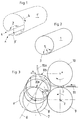
- 1 shows a straight, rounded insulating tube piece 1 ', but with open sheet metal or longitudinal edges A and E for the overlap and the attachment of a rivet connection through the rivet holes 2.
- FIG. 1 shows a straight tongue piece 3 ', which arises during a corresponding rolling process according to arrow 4.
- FIG. 2 shows an analog insulating tube piece 1, but with a shorter tongue piece 3, which is overlapped and connected by rivets 5 to the other end of the joint.
- riveting is normally only carried out directly above the insulation during assembly. The insulating pipe piece is spread apart slightly for installation, pushed onto the insulation and only then closed and riveted.
- FIG. 3 shows a comparison of the previously known straight delivery path, which is indicated by a double-dotted line 6, as well as the new arcuate delivery path 7 and. the dash-dotted line 7, an infeed shaft 8.
- a corresponding infeed shaft on the straight infeed path 6 is shown at 8 '.
- the curved feed path 7 in FIG. 3 represents a concentric circle around a center Z, which is the fixed center of rotation of a lower pinch roller 9, which together with the upper pinch roller 10 forms a pair of pinch rollers.
- the pinch roller 9 rotates counterclockwise, the pinch roller 10 clockwise, so that after the roller distance D has been set correctly, a plate 11 is drawn in by the pair of rollers.
- the two pinch rollers 9 and 10 have the same peripheral speed and would pull through the sheet 11 in a horizontal path 11 'without hindrance.
- the feed shaft 8 has to be moved upward via the feed path 7, for example into position 8a, so that the rounding is made possible and a rounded sheet 11a is produced.
- the two extreme positions, between which the infeed shaft 8 can be adjusted in any position on the infeed path 7, are represented by the reference numerals 8 and 8b.
- 8 ' shows the lowest extreme position on a straight infeed path 6.
- the infeed shaft 8 is evident on the circular feed path 7 by the dimension M closer to the pinch roller pair, so that the straight tongue piece 3 'can be shortened by a corresponding dimension M.
- FIG. 4 A round machine is shown schematically in FIG. 4, viewed from the side.
- the upper pinch roller 10 is supported at the end on a pivotable bearing bracket 33 via a bearing journal 33 'on two bearing blocks 18, 19.
- a sheet metal strip 11 is ready on a flat insertion table 12 and is inserted according to arrow 13 between the pinch roller pair 9, 10 after the required roller distance D has been set beforehand by means of tensioning screws 14 and the feed shaft 8 has been brought into the correct position on the feed path 7.
- the feed shaft 8 has the same direction of rotation as the lower pinch roller 9, so that the two may not touch.
- the feed shaft 8 is driven from the pinch roller 9 via a simple chain overdrive 15.
- the feed shaft 8 is mounted with its pivot point X in a support arm 16 which is pivotable about the center Z of the lower pinch roller 9.
- a cam disk 17, which can be rotated about a pivot point Y, is shown schematically, via which the support arm 16 and thus the feed shaft 8 are adjusted by means of an upward movement.
- FIG. 5 shows the round machine according to FIG. 4 in a longitudinal view.
- the drive is located on the left lab block 18 (also called drive block); on the right, the bearing block 19 for the bearing 20 of the clamping rollers 9 and 10, the drive block 18 and the bearing block 19 being supported on a machine bed 21 on guide rails 22.
- stops 23 arranged on both sides, drive bracket 18 and support bracket 19 can be moved into an exact position or at a corresponding distance between the two.
- the cams 17 are arranged twice on both sides of the bearing and are one Adjustment shaft 24 and a central telescopic part 25 are connected, so that an identical adjustment is guaranteed on both end sides even at different distances.
- a pair of support rollers 26 is also arranged approximately in the middle of the round machine, so that the smallest possible diameters of the pinch rollers remain dimensionally stable and do not bend in the middle.
- An angular gear 26 with a drive motor 27 is mounted on the drive bracket 18 and drives the pinch roller 9 directly, a pinion 29 and thus the pinch roller 10 being driven by a pinion 28 of the pinch roller 9.
- the pinch roller 9 and 10 are held by means of the plug-on pins 30, on which the pinch rollers can be pushed in a rotationally secure manner via key ways 31.
- a pair of beading rollers 32 can also be installed interchangeably on the arbors 30.
- FIG. 6 shows the round machine in plan with the bearing block 19 extended. For the working position, the bearing block 19 is pushed back according to arrow 34 ', so that the rounding operation can begin again according to FIG. 7.
- a straight insulating tube piece 1 is shown with two opposite beads 35 respectively. 35 '.
- the plug-on mandrel 30 of the lower clamping shaft 9 is rotatably mounted with its shaft end in the bearing block 19, which projects above it on both sides.
- the support arm 16 is designed as a U-shaped body, with two legs 35 and a web or yoke 36.
- the thigh 35 overlap on opposite sides of the bearing block 19 and have the pivot bearing 37 with which the support arm 16 is pivotally mounted about the center Z at the shaft end of the mandrel 13.
- the pivot bearing 40 for the delivery shaft 8 is located in the web 36.
- the U-shaped design of the support arm 16 makes it possible to design it rigidly relative to the loads occurring and to move the delivery shaft 8 in a precisely parallel orientation to the pinch rollers 9, 10.
- the movable upper pinch roller 10 is mounted on the pedestal 19.
- the two bearing journals 33 ' form a pivot bearing on opposite sides of the bearing block 19, on which the U-shaped bearing bracket 33 is pivotally mounted with the ends of its legs 38.
- the web or yoke 39 connecting the legs 38 of the bearing bracket 33 is the pivot bearing for the shaft end of the mandrel 30 assigned to the upper pinch roller 10.
- the U-shape of the bearing bracket 33 enables a rigid construction relative to the load occurring and thus for the upper one Pinch roller 10 an exact parallel adjustability with respect to the lower pinch roller 9th
- the mounting of the upper pinch roller 10 and the feed shaft 8 is identical on the bearing block 20.
Landscapes
- Engineering & Computer Science (AREA)
- Mechanical Engineering (AREA)
- Bending Of Plates, Rods, And Pipes (AREA)
- Lining Or Joining Of Plastics Or The Like (AREA)
- Shaping Of Tube Ends By Bending Or Straightening (AREA)
- Formation And Processing Of Food Products (AREA)
- Confectionery (AREA)
Applications Claiming Priority (2)
| Application Number | Priority Date | Filing Date | Title |
|---|---|---|---|
| CH2370/92 | 1992-07-28 | ||
| CH2370/92A CH685479A5 (de) | 1992-07-28 | 1992-07-28 | Rundmaschine. |
Publications (2)
| Publication Number | Publication Date |
|---|---|
| EP0584486A1 true EP0584486A1 (fr) | 1994-03-02 |
| EP0584486B1 EP0584486B1 (fr) | 1996-09-04 |
Family
ID=4232182
Family Applications (1)
| Application Number | Title | Priority Date | Filing Date |
|---|---|---|---|
| EP93110064A Expired - Lifetime EP0584486B1 (fr) | 1992-07-28 | 1993-06-24 | Machine a cintrer |
Country Status (4)
| Country | Link |
|---|---|
| EP (1) | EP0584486B1 (fr) |
| AT (1) | ATE142132T1 (fr) |
| CH (1) | CH685479A5 (fr) |
| DE (1) | DE59303636D1 (fr) |
Cited By (9)
| Publication number | Priority date | Publication date | Assignee | Title |
|---|---|---|---|---|
| EP1046437A1 (fr) * | 1999-04-09 | 2000-10-25 | Bertoni, Mariangela | Machine à cintrer avec un cabestan centrale entraíné |
| CN102248035A (zh) * | 2011-07-16 | 2011-11-23 | 长治钢铁(集团)锻压机械制造有限公司 | 折叠式外托架装置 |
| EP2449316A1 (fr) | 2009-07-02 | 2012-05-09 | Marco Zambolin | Procédé pour réaliser des modules de canalisations d installations de distribution d air, module de canalisation, et procédé d emballage et procédé d assemblage desdits modules |
| CN105170725A (zh) * | 2015-07-23 | 2015-12-23 | 浙江德清森朗装饰材料有限公司 | 卷板机 |
| CN109500157A (zh) * | 2018-12-10 | 2019-03-22 | 江苏宏宝优特管业制造有限公司 | 一种钢带窄向压弯变形器及窄向压弯方法 |
| CN111015233A (zh) * | 2019-12-27 | 2020-04-17 | 巢湖市金辉自控设备有限公司 | 一种管材自动弯管切割机 |
| CN111790785A (zh) * | 2020-06-15 | 2020-10-20 | 陕西斯瑞新材料股份有限公司 | 一种侧弧形铜排的成型装置及方法 |
| CN114309160A (zh) * | 2020-07-01 | 2022-04-12 | 德重机电(吉林)有限公司 | 一种数控仿形薄板滚圆机 |
| CN114798856A (zh) * | 2022-04-27 | 2022-07-29 | 安徽省三信重工机械制造有限公司 | 一种高效的折弯机 |
Families Citing this family (2)
| Publication number | Priority date | Publication date | Assignee | Title |
|---|---|---|---|---|
| EP3851221B1 (fr) | 2020-01-16 | 2022-05-18 | MABI AG Isoliermaschinen | Machine à cintrer |
| CN111558662A (zh) * | 2020-06-19 | 2020-08-21 | 徐敏旺 | 一种铁质片状五金零部件压弯装置 |
Citations (8)
| Publication number | Priority date | Publication date | Assignee | Title |
|---|---|---|---|---|
| US2466653A (en) * | 1947-02-14 | 1949-04-05 | Nat Electric Welding Machines | Barrel bending machine |
| GB1036555A (en) * | 1965-06-10 | 1966-07-20 | Sven Ragnar Anderson | Improvements in or relating to plate-bending devices |
| FR1550173A (fr) * | 1966-08-22 | 1968-12-20 | ||
| FR1553901A (fr) * | 1967-11-29 | 1969-01-17 | ||
| GB1193970A (en) * | 1966-10-14 | 1970-06-03 | Eric Hordon | Improvements relating to Metal Rolling Machines |
| FR2154804A1 (fr) * | 1971-10-01 | 1973-05-11 | Verrina Spa | |
| FR2214534A1 (fr) * | 1973-01-23 | 1974-08-19 | Lisse Ets | |
| DE3615771A1 (de) * | 1986-05-10 | 1987-11-12 | Reinhardt Gmbh Maschbau | Verfahren und vorrichtung zum rundbiegen von blechen |
-
1992
- 1992-07-28 CH CH2370/92A patent/CH685479A5/de not_active IP Right Cessation
-
1993
- 1993-06-24 EP EP93110064A patent/EP0584486B1/fr not_active Expired - Lifetime
- 1993-06-24 DE DE59303636T patent/DE59303636D1/de not_active Expired - Lifetime
- 1993-06-24 AT AT93110064T patent/ATE142132T1/de not_active IP Right Cessation
Patent Citations (8)
| Publication number | Priority date | Publication date | Assignee | Title |
|---|---|---|---|---|
| US2466653A (en) * | 1947-02-14 | 1949-04-05 | Nat Electric Welding Machines | Barrel bending machine |
| GB1036555A (en) * | 1965-06-10 | 1966-07-20 | Sven Ragnar Anderson | Improvements in or relating to plate-bending devices |
| FR1550173A (fr) * | 1966-08-22 | 1968-12-20 | ||
| GB1193970A (en) * | 1966-10-14 | 1970-06-03 | Eric Hordon | Improvements relating to Metal Rolling Machines |
| FR1553901A (fr) * | 1967-11-29 | 1969-01-17 | ||
| FR2154804A1 (fr) * | 1971-10-01 | 1973-05-11 | Verrina Spa | |
| FR2214534A1 (fr) * | 1973-01-23 | 1974-08-19 | Lisse Ets | |
| DE3615771A1 (de) * | 1986-05-10 | 1987-11-12 | Reinhardt Gmbh Maschbau | Verfahren und vorrichtung zum rundbiegen von blechen |
Cited By (12)
| Publication number | Priority date | Publication date | Assignee | Title |
|---|---|---|---|---|
| EP1046437A1 (fr) * | 1999-04-09 | 2000-10-25 | Bertoni, Mariangela | Machine à cintrer avec un cabestan centrale entraíné |
| EP2449316A1 (fr) | 2009-07-02 | 2012-05-09 | Marco Zambolin | Procédé pour réaliser des modules de canalisations d installations de distribution d air, module de canalisation, et procédé d emballage et procédé d assemblage desdits modules |
| CN102248035A (zh) * | 2011-07-16 | 2011-11-23 | 长治钢铁(集团)锻压机械制造有限公司 | 折叠式外托架装置 |
| CN105170725A (zh) * | 2015-07-23 | 2015-12-23 | 浙江德清森朗装饰材料有限公司 | 卷板机 |
| CN109500157A (zh) * | 2018-12-10 | 2019-03-22 | 江苏宏宝优特管业制造有限公司 | 一种钢带窄向压弯变形器及窄向压弯方法 |
| CN109500157B (zh) * | 2018-12-10 | 2023-09-12 | 江苏宏宝优特管业制造有限公司 | 一种钢带窄向压弯变形器及窄向压弯方法 |
| CN111015233A (zh) * | 2019-12-27 | 2020-04-17 | 巢湖市金辉自控设备有限公司 | 一种管材自动弯管切割机 |
| CN111790785A (zh) * | 2020-06-15 | 2020-10-20 | 陕西斯瑞新材料股份有限公司 | 一种侧弧形铜排的成型装置及方法 |
| CN111790785B (zh) * | 2020-06-15 | 2022-06-03 | 陕西斯瑞新材料股份有限公司 | 一种侧弧形铜排的成型装置及方法 |
| CN114309160A (zh) * | 2020-07-01 | 2022-04-12 | 德重机电(吉林)有限公司 | 一种数控仿形薄板滚圆机 |
| CN114798856A (zh) * | 2022-04-27 | 2022-07-29 | 安徽省三信重工机械制造有限公司 | 一种高效的折弯机 |
| CN114798856B (zh) * | 2022-04-27 | 2024-03-29 | 安徽省三信重工机械制造有限公司 | 一种高效的折弯机 |
Also Published As
| Publication number | Publication date |
|---|---|
| EP0584486B1 (fr) | 1996-09-04 |
| DE59303636D1 (de) | 1996-10-10 |
| CH685479A5 (de) | 1995-07-31 |
| ATE142132T1 (de) | 1996-09-15 |
Similar Documents
| Publication | Publication Date | Title |
|---|---|---|
| EP1591174B1 (fr) | Dispositif de pliage pour des pièces en forme de barre et de tube | |
| EP2529849A2 (fr) | Dispositif et procédé de fabrication de tuyaux fendus à partir de plaques de tôle | |
| EP0584486B1 (fr) | Machine a cintrer | |
| DE3033300C2 (fr) | ||
| DE3042383C2 (fr) | ||
| EP0563575A2 (fr) | Procédé et dispositif de production en continu d'un tube composite avec manchon | |
| EP1382402B1 (fr) | Dispositif pour la fabrication de tubes à partir de tôles | |
| EP3189908A1 (fr) | Dispositif de production d'un recipient cylindrique a grand diametre, en particulier un silo | |
| DE2741001A1 (de) | Dreipunkt-blechfreibiegemaschine | |
| EP1089835A1 (fr) | Procede et dispositif pour la production de tubes a cordons de soudure longitudinaux a partir de decoupes de tole | |
| DE3016047C2 (fr) | ||
| DE3423706C2 (de) | Vorrichtung zur kontinuierlichen Stahlrohrherstellung | |
| AT408318B (de) | Vorrichtung zum kontinuierlichen walzen eines blechbandes zu einem profil mit im querschnitt geraden profilschenkeln, insbesondere zum herstellen von längsgeschweissten rechteckrohren | |
| EP0546319A1 (fr) | Procédé de pliage par étirage de profils creux et machine de pliage par étirage à mandrin | |
| DE3050764C2 (fr) | ||
| WO1996026145A1 (fr) | Dispositif suppresseur du cintrage pour machines de traitement du papier | |
| CH636802A5 (de) | Verfahren und vorrichtung zur herstellung von rohrfoermigen verpackungskoerpern aus einem thermoplastischen, waermeschrumpfenden material. | |
| DE102019006796A1 (de) | Verfahren zur Herstellung von gebogenen Profilen aus Blech, insbesondere Leichtbauprofilen, auf einer Biegemaschine sowie eine Werkzeuganordnung an einer Biegemaschine zur Herstellung von gebogenen Profilen | |
| EP0561025B1 (fr) | Dispositif pour cintrer des parties de tubes, en particulier pour la fabrication de terpentins | |
| DE4210227C2 (fr) | ||
| DE10054802C2 (de) | Verfahren zur Herstellung eines formstabilen Gelenkteiles | |
| DE3615771A1 (de) | Verfahren und vorrichtung zum rundbiegen von blechen | |
| EP3851221A1 (fr) | Machine à cintrer | |
| CH626544A5 (en) | Method and apparatus for the production of corrugated wall sheets for ventilation ducts | |
| DE102004054680B3 (de) | Rollbiegevorrichtung |
Legal Events
| Date | Code | Title | Description |
|---|---|---|---|
| PUAI | Public reference made under article 153(3) epc to a published international application that has entered the european phase |
Free format text: ORIGINAL CODE: 0009012 |
|
| AK | Designated contracting states |
Kind code of ref document: A1 Designated state(s): AT BE DE DK FR IT NL |
|
| 17P | Request for examination filed |
Effective date: 19940825 |
|
| 17Q | First examination report despatched |
Effective date: 19950209 |
|
| GRAH | Despatch of communication of intention to grant a patent |
Free format text: ORIGINAL CODE: EPIDOS IGRA |
|
| GRAA | (expected) grant |
Free format text: ORIGINAL CODE: 0009210 |
|
| GRAH | Despatch of communication of intention to grant a patent |
Free format text: ORIGINAL CODE: EPIDOS IGRA |
|
| AK | Designated contracting states |
Kind code of ref document: B1 Designated state(s): AT BE DE DK FR IT NL |
|
| PG25 | Lapsed in a contracting state [announced via postgrant information from national office to epo] |
Ref country code: NL Free format text: LAPSE BECAUSE OF FAILURE TO SUBMIT A TRANSLATION OF THE DESCRIPTION OR TO PAY THE FEE WITHIN THE PRESCRIBED TIME-LIMIT Effective date: 19960904 Ref country code: DK Effective date: 19960904 |
|
| REF | Corresponds to: |
Ref document number: 142132 Country of ref document: AT Date of ref document: 19960915 Kind code of ref document: T |
|
| REF | Corresponds to: |
Ref document number: 59303636 Country of ref document: DE Date of ref document: 19961010 |
|
| ITF | It: translation for a ep patent filed | ||
| ET | Fr: translation filed | ||
| NLV1 | Nl: lapsed or annulled due to failure to fulfill the requirements of art. 29p and 29m of the patents act | ||
| PG25 | Lapsed in a contracting state [announced via postgrant information from national office to epo] |
Ref country code: AT Free format text: LAPSE BECAUSE OF NON-PAYMENT OF DUE FEES Effective date: 19970624 |
|
| PG25 | Lapsed in a contracting state [announced via postgrant information from national office to epo] |
Ref country code: BE Effective date: 19970630 |
|
| PLBE | No opposition filed within time limit |
Free format text: ORIGINAL CODE: 0009261 |
|
| STAA | Information on the status of an ep patent application or granted ep patent |
Free format text: STATUS: NO OPPOSITION FILED WITHIN TIME LIMIT |
|
| 26N | No opposition filed | ||
| BERE | Be: lapsed |
Owner name: MABI A.G. ISOLIERMASCHINEN Effective date: 19970630 |
|
| PGFP | Annual fee paid to national office [announced via postgrant information from national office to epo] |
Ref country code: DE Payment date: 20120622 Year of fee payment: 20 |
|
| PGFP | Annual fee paid to national office [announced via postgrant information from national office to epo] |
Ref country code: FR Payment date: 20120705 Year of fee payment: 20 |
|
| PGFP | Annual fee paid to national office [announced via postgrant information from national office to epo] |
Ref country code: IT Payment date: 20120628 Year of fee payment: 20 |
|
| REG | Reference to a national code |
Ref country code: DE Ref legal event code: R071 Ref document number: 59303636 Country of ref document: DE |
|
| PG25 | Lapsed in a contracting state [announced via postgrant information from national office to epo] |
Ref country code: DE Free format text: LAPSE BECAUSE OF EXPIRATION OF PROTECTION Effective date: 20130625 |