EP0584587B1 - Interrupteur à fusible avec coupure de la tension aux deux cÔtés - Google Patents
Interrupteur à fusible avec coupure de la tension aux deux cÔtés Download PDFInfo
- Publication number
- EP0584587B1 EP0584587B1 EP93112359A EP93112359A EP0584587B1 EP 0584587 B1 EP0584587 B1 EP 0584587B1 EP 93112359 A EP93112359 A EP 93112359A EP 93112359 A EP93112359 A EP 93112359A EP 0584587 B1 EP0584587 B1 EP 0584587B1
- Authority
- EP
- European Patent Office
- Prior art keywords
- contact
- switch
- blocking
- switch according
- contact bridge
- Prior art date
- Legal status (The legal status is an assumption and is not a legal conclusion. Google has not performed a legal analysis and makes no representation as to the accuracy of the status listed.)
- Expired - Lifetime
Links
Images



Classifications
-
- H—ELECTRICITY
- H01—ELECTRIC ELEMENTS
- H01H—ELECTRIC SWITCHES; RELAYS; SELECTORS; EMERGENCY PROTECTIVE DEVICES
- H01H9/00—Details of switching devices, not covered by groups H01H1/00 - H01H7/00
- H01H9/10—Adaptation for built-in fuses
- H01H9/104—Adaptation for built-in fuses with interlocking mechanism between switch and fuse
-
- H—ELECTRICITY
- H01—ELECTRIC ELEMENTS
- H01H—ELECTRIC SWITCHES; RELAYS; SELECTORS; EMERGENCY PROTECTIVE DEVICES
- H01H1/00—Contacts
- H01H1/12—Contacts characterised by the manner in which co-operating contacts engage
- H01H1/14—Contacts characterised by the manner in which co-operating contacts engage by abutting
- H01H1/20—Bridging contacts
Definitions
- the invention relates to a fuse switch for fuse links with the features of the preamble of claim 1.
- Such safety switches are e.g. known from EP-A1-0 242 664. They each have a connection terminal for the line leading to the electrical consumer and for the line coming from the network. The two connection terminals are each electrically conductively connected to the fuse link via a current path, so that the latter is in series with the two connection terminals.
- a switch contact is arranged in the current path connected to the line coming from the network. The switching contact can be switched by hand using a switching knob.
- the fuse link can only be removed from the circuit breaker when the switch toggle is pivoted into its off position. The switch contact interrupts the current path assigned to it.
- the melting insert can then be removed and exchanged completely safely in the de-energized and de-energized state.
- the line is fed to a safety switch of the type mentioned at the foot contact thereof, namely in a region that is structurally far removed from the positioning of the fuse.
- the customary arrangement of the line routing already corresponds to this customary in most cases.
- the fuse switch is installed in such a way that it is switched off by swiveling its switch toggle downwards.
- compliance with these requirements and customary practices is not easy to assume, particularly in foreign countries.
- the object of the invention consequently consists in designing the safety switch mentioned at the outset in such a way that there is no safety impairment even when a line is fed to the other connection terminal.
- the switch can be used universally regardless of different installation habits, e.g. in vertical boxes. It may also be necessary to connect the two terminals interchanged due to space problems in control panel construction. With the safety switch according to the invention, this is easily possible, taking into account the VDE safety requirements. A twisted installation of the fuse switch and the resulting the necessary interchanged connection of the mains and consumer line result in improved handling of the switching knob.
- the movable foot contact becomes potential-free while the melting insert is being removed, so that touching the contact bridge by an operator is completely harmless.
- the two functional positions of the contact bridge are produced in a simple and safe manner. An inadvertent change of the functional position is not possible due to the forces acting on the foot pressure spring or the melt insert.
- Claim 4 relates to a preferred embodiment of a safety lock for the circuit breaker.
- the safety lock means that the safety switch can only be switched on when the fuse is fully inserted and is live.
- the switch toggle In order to be able to remove the fuse link from the safety switch, the switch toggle must first be pivoted into its off position. As a result, the safety switch reaches its de-energized state, which is necessary for the safety of the operator. Since the switch toggle remains locked in its switch-off position when the melting insert is removed, the switch contact cannot be switched on accidentally. This ensures that the parts of the circuit breaker that are freely accessible while the switch toggle is switched off are de-energized and de-energized.
- the contact bridge receives a double function.
- the opening movement of the contact bridge causes its potential freedom, on the other hand, it acts on the switch toggle via the locking slide.
- This dependency on the functional position of the contact bridge and switching knob is expediently used in such a way that the locking slide ensures that the switching knob remains locked while the contact bridge is in the open position causes. This supports the reliable functioning of the security lock.
- Claim 6 relates to an expedient sequence of changes in the functional positions of the shift knob and the foot contact, in order to ensure the sufficient safety of the operator during the replacement of a melting insert.
- Claims 7 and 8 relate to preferred embodiments and arrangements of the contact bridge within the switch housing.
- the contact bridge thus has a multiple function. In this way, the circuit breaker can be manufactured with a few components.
- Claim 9 relates to an excellent embodiment and arrangement of the foot pressure spring. This enables a secure transfer of the contact bridge between its contact position and its open position. The arrangement of the foot pressure spring ensures that the contact bridge is in its contact position only when the melt insert is fully inserted.
- the contact bridge is acted upon by its displacement on the one hand by the foot pressure spring and on the other hand by a housing stop acting against its spring pressure.
- the contact bridge is thereby clamped between the foot pressure spring and the housing stop. This ensures that the contact bridge is mounted in a stationary and thus reliable manner during its open position.
- the locking slide arranged according to claim 11 is suitable for transmitting the displacement movements of the contact bridge to other components of the safety switch. These components are preferably assigned to the locking mechanism. In this way, the mode of operation of the safety lock depends on the functional position of the contact bridge.
- This locking slide is also suitable for fixing the foot pressure spring. This ensures the desired power transmission of the foot pressure spring to the contact bridge.
- the gate valve has the additional function of fixing the melting insert. This makes it easier for the operator to insert the melting insert. It also ensures that the melt insert is contacted at the correct point with the contact bridge. Appropriate dimensioning of the gate valve can prevent melt inserts with incorrect nominal current strengths from being inserted into the circuit breaker. This is an additional security against damage to the electrical consumer caused by excessive currents.
- a fixed mounting of the gate valve is also possible during the open position of the contact bridge.
- the gate valve is clamped between a housing stop and the contact bridge. Accidental displacements and the resulting malfunction of the gate valve are therefore avoided.
- Claim 15 relates to a simple mechanical coupling between locking slide and shift knob. In this way, a dependency between the functional positions of the shift toggle and the locking slider is possible in a simple manner. This dependency can be used to improve the operation of the safety lock of the fuse switch.
- Claim 16 relates to a preferred embodiment and arrangement of the locking projection.
- the locking projection designed as a locking pawl is advantageously suitable as a locking element for locking with the gear knob hub according to claim 15.
- the swivel bearing of the pawl is suitable for space-saving movements between their functional positions. This contributes to the fact that the dimensions of the switch housing can be kept small and thus the safety switch can also be used in confined spaces.
- the pawl and the locking slide are easily coupled to each other in terms of drive.
- the torsion spring as the drive connection between the locking slide and pawl is an inexpensive one Solution.
- the torsion spring creates the prerequisite for the pawl to be moved into its respective functional position by the space-saving pivoting movements.
- Claim 18 relates to a preferred embodiment of the torsion spring. This improves the pivoting effectiveness of the torsion spring and thus ensures that the pawl operates correctly. Since the pawl influences the functional positions of the switching knob, the torsion spring also takes into account the operational safety of the safety switch.
- a pawl designed according to claim 19 helps to precisely coordinate its functional position depending on the position of the locking slide. This avoids malfunctions in the functioning of the entire locking mechanism.
- the pivot axes of the components arranged in accordance with claim 20 enable a space-saving dimensioning of the fuse switch. This enables its installation even in small installation spaces. Swivel axes arranged in this way also facilitate simple mechanical coupling between the components. No complicated coupling elements are necessary for the power transmission between the individual components. This reduces the cost of the fuse switch with a very effective power transmission and thus safe operation of the locking mechanism.
- Claim 21 relates to a preferred embodiment of the pawl and the shift knob hub. This improves the secure locking of the shift knob.
- a shift knob hub designed according to claim 22 enables the shift knob to be locked in several functional positions. Certain intermediate positions of individual components can thus be taken into account by the locking mechanism, without the operational safety of the safety switch being impaired.
- Claim 23 relates to a further embodiment of the shift knob hub. This gives it a double function. As a result, the construction effort is kept low, so that the safety switch can be manufactured inexpensively.
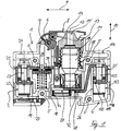
- the switch housing 4 of the fuse switch 1 is made of plastic. It is essentially cuboid and made up of two housing shells. The two housing half-shells lying one above the other in the plane of the drawing in FIG. 1 are fixed to one another in a fixed manner by four raw rent 5.
- the tubular rivets 5 penetrate corresponding holes in the housing half-shells perpendicular to the plane of the drawing.
- Another bearing tube rivet 6 arranged parallel to the tubular rivets 5 likewise penetrates the switch housing 4. It forms the pivot bearing 7 for a switch toggle 8.
- the switch toggle 8 is in its switched-on position and runs essentially parallel to a longitudinal direction 9. Viewed in the longitudinal direction 9 the switch toggle 8 is arranged in the central region of the switch housing 4. It limits the construction of the switch housing 4 in a height direction 10 running perpendicular to the longitudinal direction 9. The two side regions of the switch housing 4 adjoining the switching knob 8 in the longitudinal direction 9 have a lower construction height in the height direction 10.
- a melting insert 11 is inserted in the central region of the switch housing 4 delimited by the switching knob 8. Its axial axis 12 corresponds to the height direction 10.
- the melting insert 11 is fixed to a cylindrical screw cap 13.
- the screw cap 13 is located between the melting insert 11 and the switching knob 8.
- the switching knob 8 covers the screw cap 13 in its switched-on position.
- a cylindrical viewing opening 14 which breaks through the switching knob 8 in the vertical direction 10 provides a view of a circular viewing window 15. It is arranged centrally around the axial axis 12 on the screw cap 13 and breaks through the latter in the vertical direction 10.
- the viewing window 15 serves to display the state of the melting insert 11.
- the melt insert 11 is surrounded by a round thread 16 which is firmly connected to the screw cap 13.
- the round thread 16 protrudes further into the interior of the switch housing 4 as viewed in the height direction 10 than the screw cap 13.
- the free end of the round thread 16 facing away from the switching knob 8 in the height direction 10 is screwed to a pair of threaded glasses 17 arranged in the switch housing 4.
- the threaded goggles 17 are electrically conductively connected to the connecting terminal 2 by a switching contact 18.
- the connecting terminal 2 consists essentially of a terminal body 19, the bracket-free end 20 of a contact bracket 21 and a clamping screw 22 running parallel to the longitudinal direction 9.
- the contact bracket 21 is fixed in position within the switch housing 4. Another part of the contact bracket 21 is connected to the bracket-free end 20 at right angles in the vertical direction 10. Then the contact bracket 21 is bent at right angles in the height direction 9. This part of the contact bracket 21 is connected to the switching contact 18 in an electrically contacting manner. In this area, the contact bracket 21 is penetrated by the clamping screw 22 extending in the height direction 10. The screw end facing away from the screw head of the clamping screw 22 abuts the bracket-free end 20.
- the clamping body 19 is screwed to the clamping screw 22. It rests on the side walls of the switch housing 4 and on the region of the contact bracket 21 running in the height direction 10. The clamping body 19 is thereby mounted displaceably in the height direction 10. To connect the line coming from the network or leading to the consumer and not shown here, this is carried out through a line opening 23 which breaks through the switch housing 4 in the longitudinal direction 9 in the region of the connecting terminal 2 and is brought into the space between the clamping body 19 and the bracket-free end 20. The necessary clamping pressure is achieved by turning the clamping screw 22. For this purpose, a screwdriver engages the clamping screw 22 through a screw opening 24 arranged on the switch housing 4.
- the terminal 102 is located on the opposite side of the switch housing 4 in the longitudinal direction 9.
- the clamping body 119, the free end 120, the clamping screw 122, the line opening 123 and the screw opening 124 the explanations for the corresponding parts in the area of the terminal 2 apply analogously.
- the bracket-free end 120 in the area of the connection terminal 102 is the end area of a bridge bracket 25.
- the bridge bracket 25 is fixed in place in the switch housing 4. Starting from its bracket-free end 120, it is bent at right angles in the height direction 10. Then the bridge bracket 25 is bent at right angles in the longitudinal direction 9 in the area of the screw head of the clamping screw 122.
- the bridge bracket 25 kinks in the direction of a contact bridge 27, running at an angle to the height direction 10. This is followed by an end section of the bridge bracket 25 which runs in the height direction 9 and acts as a contact end 28.
- the contact bridge 27 extends in the longitudinal direction 9 and covers the contact end 28 with its end region facing the bridge bracket 25.
- the fusible insert 11 acts on the contact bridge 27 in such a way that between the latter and the contact end 28 there is sufficient contact pressure for establishing an electrically conductive connection between the connection terminals 102 and the contact bridge 27 is made.
- the melt insert 11 is electrically connected in series between the round thread 16 and the contact bridge 27.
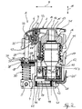
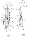
- the fuse switch 1 shows the central area of the fuse switch 1 with the switch toggle 8 and the fuse link 11.
- the fuse switch 1 has a switching mechanism consisting of the switch toggle 8, a pressure plunger 29, the switching contact 18 and a contact spring 30 for switching the switching contact 18 on and off.
- the shift knob 8 is a two-armed lever with an actuating arm 31 and a shift knob hub 32 with a partially cylindrical outer contour.
- the actuating arm 31 merges into the shift knob hub 32 serving as the shift knob bearing body.
- the pivot bearing 7 penetrates the shift knob hub 32 approximately in its central area.
- the actuating arm 31 and the shift knob hub 32 are connected to one another in an articulated manner by a predetermined articulated joint 3.
- the predetermined articulated joint 33 is acted upon by an articulated torsion spring 34.
- the axis of rotation of the articulated joint 33 penetrates the two adjoining areas of the actuating arm 31 and the toggle hub 32 parallel to the axis of the pivot bearing 7.
- the articulated joint 33 protects the safety switch 1 against violent transfer of the toggle switch 8 into its switch-on position when the melting insert 11 is not inserted and thus the locked toggle switch 8 ( Fig. 6).
- the structure and mode of operation of such a toggle 8 is described in DE-C1-3 445 285.
- a guide groove 35 is formed on the toggle hub 32 in the circumferential direction.
- the guide groove 35 positively encompasses the end of the pressure tappet 29 facing it.
- the pressure tappet 29 is arranged approximately in the height direction 10.
- the contact-side end 36 of the pressure plunger 29 facing the switching contact 18 lies between two parallel guide webs 37, 137, which are fixed to the housing and run in the vertical direction 10. As a result, the plunger 29 is guided in the height direction 10.
- a play compensation spring 38 is located in the contact-side end 36 between the pressure plunger 29 and the switching contact 18. It compensates for the manufacturing tolerances of the components.
- the underside of the switching contact 18 facing away from the pressure plunger 29 in the height direction 10 is acted upon by the contact spring 30 in the height direction 10 in the manner of a pressure spring.
- the contact spring 30 is mounted in the housing. The switching mechanism causes the switching contact 18 to be in its contact closing position during the switch knob 8 is in the on position.
- the threaded eyeglasses 17 are connected in an electrically conductive manner to the connecting terminal 2 (FIG. 1) via a threaded base 39 which is produced in one piece and extends in the longitudinal direction 9.
- the melting insert 11 lying in its inserted position exerts a compressive force in the height direction 10 with its foot contact neck 40 lying directly against the contact bridge 27.
- This area of the contact bridge 27 acts as a contact arm 41.
- the contact arm 41 is designed to be slightly convex in its area directly adjacent to the foot contact neck 40.
- the surface area of the contact bridge 27 facing the contact end 28 forms a foot contact 42.
- the melting insert 11 pressurizes the contact bridge 27 in its inserted position such that the foot contact 42 and the contact end 28 lie directly against one another with their surfaces facing one another.
- the contact bridge 27 is thereby in its contact position and is electrically conductively connected to the connection terminal 102 (FIG. 1).
- the contact bridge 27 is part of the locking mechanism of the fuse switch 1. The structure of the locking mechanism is explained in more detail in FIG. 3.
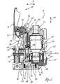
- the switch toggle 8 is in its off position. For this purpose, it is rotated about the pivot bearing 7 against a closing direction 43 starting from its switched-on position (FIG. 2) by approximately 90 °.
- the switch contact 18 is in its contact opening position.
- the melting insert 11 is in its inserted position, so that the contact bridge 27 is still connected to the bridge bracket 25 in an electrically conductive manner.
- the locking mechanism consists essentially of a foot pressure spring 44, the contact bridge 27, a locking slide 45, a torsion spring 46, a pawl 47 and the guide groove 35.
- the foot compression spring 44 lies between the contact bridge 27 and a bottom of the switch housing 4.
- the foot compression spring 44 is fixed in position by a centering pin 48 integrally formed on the locking slide 45 and cannot be moved accidentally in the longitudinal direction 9.
- the foot pressure spring 44 acts on the contact bridge 27 essentially in an area which acts as a drive arm 49.
- the end region of the contact bridge 27 facing the contact spring 30 is acted upon by a peripheral region of the foot compression spring 44.
- the other circumferential region of the foot compression spring 44 acts on the contact bridge 27 at an intersection formed with the axial axis 12.
- the surface of the contact bridge 27 facing the foot compression spring 44 is curved slightly concavely.
- the extension of the centering pin 48 in the longitudinal direction 9 corresponds to the inside diameter of the foot pressure spring 44.
- the housing 10 is connected to the outside diameter of the foot pressure spring 44 in the height direction. In this way, the foot compression spring 44 is adequately protected against displacements in the longitudinal direction 9.
- the locking slide 45 is composed of the centering pin 48 and a cuboid slide valve 50.
- the expansion of the slide housing 50 in the longitudinal direction 9 is greater than in the vertical direction 10.
- the locking slide 45 can hardly be moved in the longitudinal direction 9, since the side walls of the slide housing 50 are affected by projections fixed to the housing in the vertical direction 10. Due to the pressure forces of the melt insert 11 and the foot pressure spring 44, this results in only a displaceability of the locking slide 45 in the height direction 10. In FIG. 3, the locking slide 45 is in its rest position.
- the slide housing 50 is pierced centrally around the axial axis 12 by a hollow cylindrical neck opening 51.
- the foot contact neck 40 of the melting insert 11 engages in the neck opening 51.
- the lateral surface of the foot contact neck 40 is pressurized by two neck clips 52, 152 diametrically opposite in the longitudinal direction 9.
- the neck brackets 52, 152 lie within the neck opening 51 and fix a fitting ring 153. By suitable dimensioning of the fitting ring 153 it can be avoided that a fuse link 11 with the wrong nominal current is inserted into the fuse switch 1.
- the contact bridge 27 is clamped between the mutually facing surfaces of the centering pin 48 and the slide housing 50.
- the locking slide 45 is thereby coupled to the contact bridge 27 in terms of drive.
- a journal 53 is integrally formed on the sliding housing 50.
- the longitudinal axis of the journal 53 runs perpendicular to the plane of the drawing in FIG. 3. It serves to fix the torsion spring 46.
- the two legs of the torsion spring 46 of different lengths are aligned approximately in the height direction 10 and each rest on an outer surface of the pawl 47.
- the shorter of the two legs is arranged between threaded glasses 17 and pawl 47 and is effective as a locking leg 54.
- the opening leg 55 opposite this leg in the longitudinal direction 9 faces the switching contact 18 and is arranged between a leg stop 56 fixed to the housing in the vertical direction 10 and the pawl 47.
- the opening leg 55 runs exactly in the height direction 10 and lies directly against the leg stop 56.
- the locking leg 54 is slightly angled in the direction of the leg stop 56 with respect to the height direction 10.
- the leg ends of the locking leg 54 and opening leg 55 are each bent at right angles and arranged perpendicular to the plane of the drawing in FIG. 3.
- Locking leg 54 and opening leg 55 abut the pawl 47 approximately in the region of a pivot axis 57.
- the pivot axis 57 is a cylindrical pin integrally formed on the pawl 47. It is fixed to the housing and rotatable and runs perpendicular to the plane of the drawing. As a result, the locking pawl 47 can be pivoted in the pivoting direction 58.
- the locking pawl 47 has a flank recess 59 extending in the height direction 10.
- the area of the pawl 47 directly adjoining the flank recess 59 corresponds in its extension in the longitudinal direction 9 approximately to the corresponding extent of the pawl 47 in the region of its pivot axis 57 an acute angle with an angular tip facing approximately to a side edge 60.
- the shorter of the two legs of this angle forms a contact surface for the side edge 60 in the engaged position of the pawl 47 (FIG. 6).
- the area of the angular tip acts as a ratchet tooth 63 of the pawl 47.
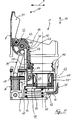
- the switch toggle 8 is in its off position.
- the actuating arm 31 no longer covers the screw cap 13, so that the melting insert 11 can be unscrewed from the threaded goggles 17.
- the melting insert 11 is slightly unscrewed in the height direction 10.
- the pressure force exerted by the melt insert 11 on the contact arm 41 is therefore reduced.
- the pressure force exerted by the foot pressure spring 44 in the area of the contact arm 41 is not sufficient to substantially change the position of the contact bridge 27 in the area of the contact arm 41.
- the contact bridge 27 acts as a two-armed lever with a pivot point arranged on the axial axis 12 between the foot contact neck 40 and the foot compression spring 44. Starting from this fulcrum, only the end region of the drive arm 49 facing away from the contact arm 41 is acted upon by the foot pressure spring 44 in the direction of a latching stop 61 fixed to the housing. Therefore, the foot contact 42 remains in its contact position with the contact end 28.
- the torsion spring 46 fixed to the slide housing 50 is also displaced in the height direction 10.
- the locking leg 54 and the opening leg 55 are shifted on the outer surfaces of the pawl 47 in the direction of the locking tooth 63.
- the pawl 47 is in its locked position during the open position of the contact bridge 27.
- Fig. 6 the pawl 47 engages in the locking position in the guide groove 35 of the shift knob 8.
- the switch toggle 8 is pivoted from its off position (FIG. 5) in the closing direction 43.
- the pivoting of the shift knob 8 is limited by the action of the ratchet tooth 63 as a detent.
- the side edge 60 of the guide groove 35 bears against the surface of the ratchet tooth 63 facing it.
- the switching knob 8 can therefore not be pivoted further in the closing direction 43, so that the switching contact 18 remains in its contact opening position.
- Fig. 7 the locking slide 45 is in its rest position. Accordingly, the pawl 47 is in its release position.
- the pawl axis 64 assigned to the pawl 47 extends exactly in the vertical direction 10.
- the pawl axis 64 is formed by the straight line connecting the angular tip of the pawl 63 and the center of the pivot axis 57.
- the locking leg 54 acts on the locking pawl 47 only in its area of the pivot axis 57.
- the locking pawl 47 is therefore not effective as a lever and cannot be pivoted in the pivoting direction 58.
- the opening leg 55 acts on a pawl knob 65 which is integrally formed on the pawl 47.
- the pawl 65 protrudes somewhat beyond the pivot axis 57 in the longitudinal direction 9.
- the locking leg 54 is biased in the pivoting direction 58.
- the opening leg 55 is biased against the pivoting direction 58. Because of its greater length, the opening leg 55 does not act on the pawl 47 in the region of its pivot axis 57, but rather on the pawl knob 65. Overall, this results in a pivoting movement of the pawl 47 against the pivoting direction 58. However, this pivoting movement is prevented by the screw cap 13.
- the pawl 47 rests with its surface facing the screw cap 13 on the latter. In this way, the pawl 47 always remains in its release position, while the locking slide 45 is in its rest position.
- the opening leg 55 slides with its leg end along the ratchet knob 65 and then falls into the flank recess 59 due to its pretension against the pivoting direction 58. Seen in the longitudinal direction 9, the pawl 47 is less extended in this area. Therefore, the leg end of the opening leg 55 does not form an abutment to prevent a pivoting movement of the pawl 47 in the pivoting direction 58.
- the pawl 45 engages the pawl 47 in such a way that it produces a lever effect on the pawl 47 in the pivoting direction 58.
- the pawl 47 can therefore be pivoted out of their release position (FIG. 7) in the pivoting direction 58 into their blocking position (FIG. 8).
- the pivoting is limited solely by an extension of the leg stop 56 extending in the height direction 10.
- the pretensioning of the opening leg 55 on the former causes practically no force attack against the pivoting direction 58. Because of the pretensioning of the pawl 47 in the pivoting direction 58 on the pawl 47, the pawl 47 therefore always remains in its position during the locking position of the locking slide 45 Locked position.
- the pressure plunger 29 is not locked during the half-open position of the switching knob 8.
- the pressure force of the contact spring 30 therefore causes a pivoting movement of the switching knob 8 in the closing direction 43.
- this pivoting movement is prevented by the pawl 47 lying in its locked position.
- the toggle hub 32 has an acute-angled locking recess 67 on its circumferential area.
- the locking recess 67 is arranged adjacent to the side edge 60 against the closing direction 43. Due to the pivoting movement of the switching knob 8 in the closing direction 43, the pawl 47 engages with its pawl tip 63 in the locking recess 67. A further pivoting movement of the switching knob 8 in the closing direction 43 is therefore blocked, so that the switching contact 18 remains in its contact opening position.
- connection terminal 2 Inadvertent swapping of the connection terminals when connecting the lines coming from the network and the lines leading to the electrical consumer does not impair the safety of an operator
- the switch toggle 8 To remove the melting insert 11, the switch toggle 8 must be pivoted in its switched-off position against the closing direction 43 (FIG. 3).
- the switch contact 18 is in this case moved into its contact opening position, so that the current path within the fuse switch 1 is interrupted.
- the fuse switch 1 is in the de-energized state.
- the threaded glasses 17 is therefore separated from the potential of the terminal 2 during When the melting insert 11 is unscrewed, the contact bridge 27 is moved into its open position and is therefore isolated from the potential of the connection terminal 102 (FIG. 5).
- the pawl 47 is first pivoted into its blocking position. Then the contact between foot contact 42 and contact end 28 is opened.
- fuse switch 1 always remains switched off in the case of undefined contact conditions.
- the threaded goggles 17 and the contact bridge 27 form the parts of the current path which are freely accessible when the melting insert 11 is removed, within the fuse switch 1. However, because these parts are potential-free, accidental contact is completely harmless. This effect is independent of which connection terminal 2,102 the line coming from the network is connected to.
- the switching contact can only be switched on when the melting insert 11 is fully inserted and produces the necessary contact pressure between foot contact 42 and contact end 28 for safe operation of the fuse switch 1. Only when the melting insert 11 is fully inserted is the pawl 47 pivoted out of its blocking position into its release position against the pivoting direction 58. Even if the melt insert 11 is only slightly unscrewed, this necessary contact pressure is no longer present. This causes the pawl 47 to pivot out of its release position (FIG.
- the switch toggle 8 can therefore not be pivoted into its closed position in the closing direction 43 when the melting insert 11 is removed or not fully inserted, so that the switch contact 18 remains in its contact opening position.
- the current path inside the fuse switch 1 remains interrupted, so that there is no danger to the operator.
- the melting insert 11 can also be removed during a half-open position of the switching knob 8 (FIG. 9). During this position, the pressure plunger 29 is not locked (Fig. 3 to Fig. 6). In this case, the pressure force of the contact spring 30 is so great that the switch toggle 8 can in principle be moved back into its switched-on position (FIG. 2). This would, however also the switch contact 18 is switched on again, so that the threaded spectacles 17, when the line coming from the network is connected to the connection terminal 2, carry the network potential which is dangerous for an operator. To prevent this, the locking recess 67 is arranged on the switching knob hub 32.
- the locking pawl 47 When the melting insert 11 is removed, the locking pawl 47 is always in its locking position and therefore limits the pivoting movement of the switching knob 8 in the closing direction 43 even in its half-open position. The freely accessible parts of the current path within the fuse switch 1 therefore always remain potential-free even in this position of the switching knob 8.
Landscapes
- Switch Cases, Indication, And Locking (AREA)
- Fuses (AREA)
Claims (23)
- Interrupteur coupe-circuit (1) comprenant :- une douille fixée de façon stationnaire à l'intérieur du boîtier (4) de l'interrupteur pour y mettre en place un insert fusible (11);- un contact de commutation (18)-- agencé à l'intérieur du boîtier (4) de l'interrupteur,-- actionné à la main,-- et coupant un trajet de courant (21, 39, 17, 16) conduisant à l'insert fusible (11); et- un contact de base (42)-- situé dans l'autre trajet de courant (25) conduisant à l'insert fusible (11), et-- recevant un contact depuis l'insert fusible (11) dans sa position d'enclenchement contre la pression d'un ressort;
caractérisé en ce que
le contact de base (42) est au moins une partie d'un pont de contact (27) sollicité par une pression de ressort dans sa position d'ouverture, ledit pont de contact étant maintenu dans la position de contact par l'insert fusible (11) se trouvant en position d'enclenchement. - Interrupteur selon la revendication 1, caractérisé en ce que le pont de contact (27) est sollicité par la pression d'un ressort de compression de base (44) contre l'insert fusible (11).
- Interrupteur selon la revendication 1 ou 2, caractérisé en ce que le pont de contact (27) est sollicité par la pression approximativement en direction axiale (19) de l'insert fusible (11).
- Interrupteur selon l'une quelconque des revendications précédentes, dans lequel l'insert fusible (11) peut être amené dans sa position d'enclenchement par un capuchon (13) vissable sur une lunette filetée (17), ledit insert pouvant alors être relié au trajet de courant (21, 39, 17, 16) susceptible d'être coupé par le contact de commutation (18) et dans lequel le contact de commutation est susceptible d'être commuté par une manette de commutation (8) pivotante qui, dans la position de commutation, recouvre avec son bras d'actionnement (31) le capuchon (13) vissable de telle sorte qu'il n'est susceptible d'être vissé que lorsque la manette de commutation (8) est basculée en position de disjonction, caractérisé en ce que la manette de commutation (8) est arrêtée dans sa position de disjonction en dévissant le capuchon vissable (13) du pont de contact (27), alors amené dans sa position d'ouverture.
- Interrupteur selon la revendication 4, caractérisé en ce qu'un coulisseau de blocage (45) monté en déplacement dans le boîtier (4), situé entre le pont de contact (27) et la manette de commutation (8) est amené grâce au mouvement d'ouverture du pont de contact (27) depuis une position de repos jusque dans une position de blocage effective par rapport à la manette de commutation (8).
- Interrupteur selon l'une quelconque des revendications précédentes, caractérisé en ce que la région du contact de base a une structure telle que lorsqu'on dévisse le capuchon vissable (13) sollicitant l'insert fusible (11), tout d'abord la manette de commutation (8) est arrêtée et ensuite le contact de base (42) est ouvert, tandis que lorsqu'on le visse, se produit tout d'abord le contact, et le blocage de la manette de commutation est ensuite relâché.
- Interrupteur selon la revendication 6, caractérisé en ce que le pont de contact (27) est agencé en déplacement transversal par rapport à son extension longitudinale (9) dans le boîtier (4) de l'interrupteur et en ce qu'il sollicite avec sa face supérieure orientée vers l'insert fusible (11) non seulement l'insert fusible (11) par contact mais aussi le coulisseau de blocage (45) du point de vue entraînement, en ce qu'il est sollicité sur sa face inférieure par le ressort de compression de base (44), et en ce qu'il porte le contact de base (42).
- Interrupteur selon la revendication 7, caractérisé en ce que le pont de contact (27) contient deux bras (41, 49) de pont alignés l'un derrière l'autre dans sa direction longitudinale (9),- dont le bras de contact (41) porte le contact de base (42) et est sollicité sur sa face supérieure par l'insert fusible (11), et- dont le bras d'entraînement (49) est sollicité sur sa face inférieure par le ressort de compression de base (44) et est orienté avec sa face supérieure vers le coulisseau de blocage (45).
- Interrupteur selon l'une quelconque des revendications précédentes, caractérisé en ce que le ressort de compression de base est un ressort hélicoïdal dont la région périphérique du côté du bras de contact sollicite le pont de contact (27) sur sa région longitudinale qui fait face au contact de l'insert fusible.
- Interrupteur selon l'une quelconque des revendications précédentes, caractérisé en ce que le trajet de déplacement du pont de contact (27) est limité par une butée (61) de boîtier agissant sur le bras d'entraînement (49) contre la pression du ressort de compression de base (44).
- Interrupteur selon l'une quelconque des revendications précédentes, caractérisé en ce que le coulisseau de blocage (45) est fixé sur la face supérieure du pont de contact (27).
- Interrupteur selon l'une quelconque des revendications précédentes, caractérisé en ce que le coulisseau de blocage (45) est bridé de façon mécanique avec le pont de contact (27) et forme avec une saillie de la bride dépassant la face inférieure du pont de contact (27) un pivot de centrage (48) entouré par l'extrémité de la spire du ressort de compression de base (44).
- Interrupteur selon l'une quelconque des revendications précédentes, caractérisé en ce que le coulisseau de blocage (45) entoure à la manière d'un anneau le col (40) du contact de base de l'insert fusible (11).
- Interrupteur selon l'une quelconque des revendications précédentes, caractérisé en ce que lorsqu'on enlève l'insert fusible (11), le coulisseau de blocage (45) repose avec sa face supérieure sur une butée (62) du boîtier sous la pression du ressort de compression de base (44).
- Interrupteur selon l'une quelconque des revendications précédentes, caractérisé en ce que sur le coulisseau de blocage (45) est agencée une saillie de blocage qui peut être amenée en engagement avec un moyeu (32) de la manette de commutation (8).
- Interrupteur selon la revendication 15, caractérisé en ce que la saillie de blocage est un cliquet de blocage (47) monté en pivotement sur le boîtier (4) dont le pivotement de blocage est commandé par le coulisseau de blocage (45).
- Interrupteur selon la revendication 16, caractérisé en ce qu'un ressort de torsion (46) est fixé sur le coulisseau de blocage (45) en flanquant avec ses branches (54, 55) le cliquet de blocage (47) en contact bilatéral, de telle manière que sa branche de blocage (54) fait pivoter le cliquet de blocage (47) lorsque le coulisseau de blocage (45) est déplacé en position d'ouverture, et que sa branche d'ouverture (55) ramène le cliquet de blocage (47) dans sa position de libération lorsque le coulisseau de blocage (45) est repoussé dans la position de repos.
- Interrupteur selon la revendication 17, caractérisé en ce que la branche de blocage (54) du ressort de torsion (46) est plus courte que sa branche d'ouverture (55) de telle sorte que la branche de blocage (54) n'agit en pivotant sur le cliquet de blocage (47) que lorsque le coulisseau de blocage (45) est déplacé en direction d'ouverture tandis que l'effet de pivotement de la branche d'ouverture est alors annulé.
- Interrupteur selon la revendication 18, caractérisé en ce que l'extrémité de pression de la branche d'ouverture (55), lorsque le coulisseau de blocage (45) est déplacé en direction d'ouverture, devient inactive en pivotement en tombant dans un évidement de flanc (59) du cliquet de blocage (47).
- Interrupteur selon l'une quelconque des revendications précédentes, caractérisé en ce que tous ses axes de pivotement (7, 53, 57) sont orientés parallèlement les uns aux autres.
- Interrupteur selon l'une quelconque des revendications précédentes, caractérisé en ce que le cliquet de blocage (47) est susceptible d'être encliqueté avec une dent de blocage (63) située à son extrémité de pivotement dans un évidement de blocage (35) agencé sur la périphérie du moyeu (32) de la manette de commutation.
- Interrupteur selon la revendication 21, caractérisé en ce que plusieurs évidements de blocage (35, 67) sont répartis sur la périphérie du moyeu (32) de la manette de commutation.
- Interrupteur selon l'une quelconque des revendications précédentes, dans lequel une rainure de guidage (35) agencée sur le moyeu (32) de la manette de commutation engendre la mise en circuit et la mise hors circuit du contact de commutation (18), caractérisé en ce qu'une arête latérale (60) de la rainure de guidage (35) forme un flanc de l'évidement de blocage.
Applications Claiming Priority (2)
| Application Number | Priority Date | Filing Date | Title |
|---|---|---|---|
| DE9211229U | 1992-08-21 | ||
| DE9211229U DE9211229U1 (de) | 1992-08-21 | 1992-08-21 | Sicherungsschalter mit beidseitiger Spannungstrennung |
Publications (2)
| Publication Number | Publication Date |
|---|---|
| EP0584587A1 EP0584587A1 (fr) | 1994-03-02 |
| EP0584587B1 true EP0584587B1 (fr) | 1996-01-17 |
Family
ID=6882897
Family Applications (1)
| Application Number | Title | Priority Date | Filing Date |
|---|---|---|---|
| EP93112359A Expired - Lifetime EP0584587B1 (fr) | 1992-08-21 | 1993-08-02 | Interrupteur à fusible avec coupure de la tension aux deux cÔtés |
Country Status (2)
| Country | Link |
|---|---|
| EP (1) | EP0584587B1 (fr) |
| DE (2) | DE9211229U1 (fr) |
Cited By (1)
| Publication number | Priority date | Publication date | Assignee | Title |
|---|---|---|---|---|
| DE10115777A1 (de) * | 2001-03-29 | 2003-05-15 | Mueller Jean Ohg Elektrotech | Mehrpoliges Schaltgerät für den Einsatz auf Sammelschienensystemen |
Families Citing this family (8)
| Publication number | Priority date | Publication date | Assignee | Title |
|---|---|---|---|---|
| SI9700256A (sl) * | 1997-10-02 | 1999-06-30 | Eti Elektroelement D.D. | Električno stikalo za naprave |
| PL183078B1 (pl) * | 1997-12-04 | 2002-05-31 | Legrand Fael Sp Z Oo | Rozłącznik bezpiecznikowy |
| DE20013044U1 (de) | 2000-07-28 | 2001-11-29 | Eti Elektroelement D.D., Izlake | Sicherungslasttrennschalter |
| DE10247095B4 (de) * | 2002-10-09 | 2004-08-19 | Klaus Bruchmann | Schaltersicherungsanordnung |
| DE10334069A1 (de) * | 2003-07-25 | 2005-03-03 | Siemens Ag | Sicherungsbehaftetes Schaltschutzgerät |
| US7855873B2 (en) * | 2004-09-13 | 2010-12-21 | Cooper Technologies Company | Panelboard for fusible switching disconnect devices |
| DE102005015399B3 (de) * | 2005-04-04 | 2006-05-18 | Klaus Bruchmann | Schaltersicherungseinheit |
| FR2911994B1 (fr) | 2007-01-31 | 2009-07-03 | Ferraz Shawmut Sa | Interrupteur-sectionneur a fusible a verrouillage rapide. |
Family Cites Families (8)
| Publication number | Priority date | Publication date | Assignee | Title |
|---|---|---|---|---|
| DE125892C (fr) * | ||||
| CH88287A (de) * | 1920-05-06 | 1921-06-16 | Grossmann Tscharner & Co Auror | Schmelszicherung. |
| US1990953A (en) * | 1934-01-11 | 1935-02-12 | Nat Electric Prod Corp | Electrical cut-out |
| DE2033321A1 (de) * | 1970-07-06 | 1972-01-20 | Nolta Bonn & Tatje Kg | Uberstromschalter |
| DE2334595B1 (de) * | 1973-07-07 | 1974-04-25 | Lindner Gmbh Fabrik Elek Scher | Mit einem Schalter versehener Sicherungssockel fuer Schmelzeinsaetze |
| DE2445262A1 (de) * | 1974-09-21 | 1976-04-08 | Bbc Brown Boveri & Cie | Sicherungsschalter |
| DE3445285C1 (de) * | 1984-12-12 | 1986-04-30 | Lindner Gmbh, Fabrik Elektrischer Lampen Und Apparate, 8600 Bamberg | Sicherungsschalter |
| DE8611082U1 (de) * | 1986-04-23 | 1986-07-17 | Lindner Gmbh, Fabrik Elektrischer Lampen Und Apparate, 8600 Bamberg | Handbetätigter elektrischer Schalter |
-
1992
- 1992-08-21 DE DE9211229U patent/DE9211229U1/de not_active Expired - Lifetime
-
1993
- 1993-08-02 EP EP93112359A patent/EP0584587B1/fr not_active Expired - Lifetime
- 1993-08-02 DE DE59301449T patent/DE59301449D1/de not_active Expired - Lifetime
Cited By (1)
| Publication number | Priority date | Publication date | Assignee | Title |
|---|---|---|---|---|
| DE10115777A1 (de) * | 2001-03-29 | 2003-05-15 | Mueller Jean Ohg Elektrotech | Mehrpoliges Schaltgerät für den Einsatz auf Sammelschienensystemen |
Also Published As
| Publication number | Publication date |
|---|---|
| DE9211229U1 (de) | 1994-01-05 |
| EP0584587A1 (fr) | 1994-03-02 |
| DE59301449D1 (de) | 1996-02-29 |
Similar Documents
| Publication | Publication Date | Title |
|---|---|---|
| DE102004031110B4 (de) | Sicherungsschalter | |
| CH631573A5 (de) | Ueberstromschutzschalter mit ein- und ausschaltwippe. | |
| EP2174179B1 (fr) | Charnière de lunettes | |
| WO2016079077A1 (fr) | Borne à ressort | |
| EP0482191B1 (fr) | Borne a vis | |
| DE3526785C1 (de) | Druckknopfbetaetigter UEberstromschutzschalter | |
| DE69513746T2 (de) | Schutzschalter | |
| EP0391086B1 (fr) | Dispositeur de protection à courant excessif commandé par un bouton-poussoir | |
| EP0584587A1 (fr) | Interrupteur à fusible avec coupure de la tension aux deux côtés | |
| EP0394693B1 (fr) | Appareil de commutation de température | |
| EP0184652B1 (fr) | Interrupteur avec coupe-circuit | |
| EP1218900B1 (fr) | Dispositif permettant de poser l'arbre de commande d'un disjoncteur basse tension et disjoncteur basse tension multipolaire dote de ce dispositif | |
| DE19836754A1 (de) | Schaltwelleneinheit für Schalter | |
| EP1728260A1 (fr) | Mecanisme de commutation pour appareil de distribution d'installation electrique | |
| EP0592007B1 (fr) | Dispositif de commutation | |
| DE3620105C1 (en) | Electrical contact switch | |
| EP1028488B1 (fr) | Borne de connexion pour un appareillage d'installation électrique | |
| DE102021104244A1 (de) | Elektrische Verbindungsvorrichtung | |
| EP0565008B1 (fr) | Dispositif à bouton de contrÔle pour disjoncteur pour courant de défaut ou à courant différentiel | |
| EP0317784B1 (fr) | Levier de commande pour appareils de commutation électrique | |
| DE10043464C1 (de) | Schaltsicherungseinheit | |
| DE2717354C3 (de) | Verriegelung für Gehäuseteile eines elektrischen Installationsgerätes | |
| EP0043406B1 (fr) | Elément interrupteur de protection pour être ajouté à un appareil interrupteur construit comme interrupteur rotatif | |
| DE10345785B3 (de) | Berührungsgeschützter Sicherungsschalter | |
| DE2811441C2 (de) | Niederspannungsschutzschalter mit Kompensationsbimetall |
Legal Events
| Date | Code | Title | Description |
|---|---|---|---|
| PUAI | Public reference made under article 153(3) epc to a published international application that has entered the european phase |
Free format text: ORIGINAL CODE: 0009012 |
|
| AK | Designated contracting states |
Kind code of ref document: A1 Designated state(s): DE ES FR IT |
|
| 17P | Request for examination filed |
Effective date: 19940211 |
|
| 17Q | First examination report despatched |
Effective date: 19950616 |
|
| GRAA | (expected) grant |
Free format text: ORIGINAL CODE: 0009210 |
|
| AK | Designated contracting states |
Kind code of ref document: B1 Designated state(s): DE ES FR IT |
|
| PG25 | Lapsed in a contracting state [announced via postgrant information from national office to epo] |
Ref country code: ES Free format text: THE PATENT HAS BEEN ANNULLED BY A DECISION OF A NATIONAL AUTHORITY Effective date: 19960117 |
|
| REF | Corresponds to: |
Ref document number: 59301449 Country of ref document: DE Date of ref document: 19960229 |
|
| ITF | It: translation for a ep patent filed | ||
| ET | Fr: translation filed | ||
| PLBI | Opposition filed |
Free format text: ORIGINAL CODE: 0009260 |
|
| PLBF | Reply of patent proprietor to notice(s) of opposition |
Free format text: ORIGINAL CODE: EPIDOS OBSO |
|
| 26 | Opposition filed |
Opponent name: SIEMENS AG Effective date: 19961017 |
|
| PLBL | Opposition procedure terminated |
Free format text: ORIGINAL CODE: EPIDOS OPPC |
|
| PLBM | Termination of opposition procedure: date of legal effect published |
Free format text: ORIGINAL CODE: 0009276 |
|
| 27C | Opposition proceedings terminated |
Effective date: 19970307 |
|
| PGFP | Annual fee paid to national office [announced via postgrant information from national office to epo] |
Ref country code: FR Payment date: 20120831 Year of fee payment: 20 Ref country code: IT Payment date: 20120824 Year of fee payment: 20 Ref country code: DE Payment date: 20120821 Year of fee payment: 20 |
|
| REG | Reference to a national code |
Ref country code: DE Ref legal event code: R071 Ref document number: 59301449 Country of ref document: DE |
|
| REG | Reference to a national code |
Ref country code: DE Ref legal event code: R071 Ref document number: 59301449 Country of ref document: DE |
|
| PG25 | Lapsed in a contracting state [announced via postgrant information from national office to epo] |
Ref country code: DE Free format text: LAPSE BECAUSE OF EXPIRATION OF PROTECTION Effective date: 20130803 |