EP0584706B1 - Werkzeug für Handwerkzeugmaschinen - Google Patents
Werkzeug für Handwerkzeugmaschinen Download PDFInfo
- Publication number
- EP0584706B1 EP0584706B1 EP19930113202 EP93113202A EP0584706B1 EP 0584706 B1 EP0584706 B1 EP 0584706B1 EP 19930113202 EP19930113202 EP 19930113202 EP 93113202 A EP93113202 A EP 93113202A EP 0584706 B1 EP0584706 B1 EP 0584706B1
- Authority
- EP
- European Patent Office
- Prior art keywords
- rotation
- torque
- groove
- tool
- transmission grooves
- Prior art date
- Legal status (The legal status is an assumption and is not a legal conclusion. Google has not performed a legal analysis and makes no representation as to the accuracy of the status listed.)
- Expired - Lifetime
Links
Images

Classifications
-
- B—PERFORMING OPERATIONS; TRANSPORTING
- B25—HAND TOOLS; PORTABLE POWER-DRIVEN TOOLS; MANIPULATORS
- B25D—PERCUSSIVE TOOLS
- B25D17/00—Details of, or accessories for, portable power-driven percussive tools
- B25D17/08—Means for retaining and guiding the tool bit, e.g. chucks allowing axial oscillation of the tool bit
- B25D17/084—Rotating chucks or sockets
- B25D17/088—Rotating chucks or sockets with radial movable locking elements co-operating with bit shafts specially adapted therefor
-
- B—PERFORMING OPERATIONS; TRANSPORTING
- B25—HAND TOOLS; PORTABLE POWER-DRIVEN TOOLS; MANIPULATORS
- B25D—PERCUSSIVE TOOLS
- B25D2217/00—Details of, or accessories for, portable power-driven percussive tools
- B25D2217/003—Details relating to chucks with radially movable locking elements
- B25D2217/0034—Details of shank profiles
-
- B—PERFORMING OPERATIONS; TRANSPORTING
- B25—HAND TOOLS; PORTABLE POWER-DRIVEN TOOLS; MANIPULATORS
- B25D—PERCUSSIVE TOOLS
- B25D2217/00—Details of, or accessories for, portable power-driven percussive tools
- B25D2217/003—Details relating to chucks with radially movable locking elements
- B25D2217/0038—Locking members of special shape
- B25D2217/0042—Ball-shaped locking members
Definitions
- the invention relates to a tool for Hand machine tools according to the genus of the main claim.
- Such tools and corresponding tool holders are already known from EP 433 876 A1. Besides exist a number of similar tool holders on the market and Tool training, which is mainly characterized by the Arrangement and shape of the rotary drivers or Distinguish rotary driving grooves.
- Such kind trained tools can be in different tool holders can be used while protecting the material Torque transmission to the tool.
- Resilience of the tool by the characteristic Features of claim 1 further improved.
- the measures listed in the subclaims are advantageous Further training and improvements in the main claim specified tool possible. It is particularly advantageous if the partially opposite rotary driving grooves are the same Have volumes. Studies have shown that in the case of various possible tool holder variants torque-transmitting driver at the same point on the tool shank intervention. Therefore, the torque transmitting are advantageous Flanks in the tool shank to the location (angular position) and adapted the shape of this driver. Another advantage is one Locking groove with a leading cylindrical section, over the torques for some tool holder variants be transmitted.
- FIG. 1 shows a longitudinal view of a tool shank
- Figure 2 shows an enlarged cross section through a tool shank and a tool holder with a view from the shaft end to the tool head.
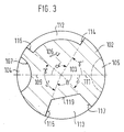
- Figure 3 also shows the shaft in cross section for a second embodiment.
- a tool shank 2 according to FIGS. 1 and 2 has a central one central axis 3 extending in the longitudinal direction of the shaft. Parallel extends to the central axis 3 on the circumference of the shaft 2 Locking groove 4 closed at both axial ends Required by a diametrically opposite second locking groove 5 be supplemented or replaced, which are shown in dashed lines in Fig. 2 is.
- the locking groove 4 has 6 in the direction of rotation Shaft 2 leading a section 7, the groove bottom 8 of one Section of a cylinder jacket is formed. Section 7 ends where it extends from the radius 9 through the central axis 3 of the shaft 2 is cut at right angles. Section 7 can be a mirror image connect a rear section 10 to the radius 9, so that the radius 9 runs through the center of the locking groove 4.
- the section 10 can also have another expedient shape, especially be cut further.
- the radius 9 spans together with the central axis 3, a central plane 11 through the shaft 2 on the bottom 8 of the locking groove 4 and / or 5 on the deepest point
- the rotary driving grooves 12, 13 are not torque-transmitting Flanks 16, 17 limited. These run preferentially also in the radial direction and are in the first embodiment placed so that the volume and thus the same groove length also the cross-sectional areas of the rotary driving grooves 12, 13 are the same. With volume, the volume of the is to generate the Only the material to be removed from the full shaft is meant.
- Figure 2 leads to angles ⁇ , ⁇ of about 53 ° for the flanks 16 and 17. That is, the flanks 15 and 17 of the deeper turning groove 13, which the locking groove 4 upstream in the direction of rotation are, compared to the central plane 11 by different angular amounts ⁇ , ⁇ 'offset.
- the rear are unloaded Flanks 16, 17 with respect to the central plane 11 in the direction of rotation seen offset by a smaller angle ⁇ , ⁇ than the respective associated torque-transmitting flank 14, 15 with its angle ⁇ ', ⁇ 'seen from the central plane 11 in the opposite direction of rotation.
- the rotary driving grooves 12, 13 each have a convex, Cylinder-section-shaped groove base 18, 19, but also a may have a different shape.
- a schematically represented tool holder With 25 a schematically represented tool holder is designated, the one radially movable, engaging in the groove 4, has spherical or cylindrical locking body 26.
- a wider, flatter rotary driver 28 fills the rotary driver groove 12 off and a narrower, longer rotary driver 29 sits in the groove 13.
- Both rotary drivers 28, 29 are each on the assigned torque-transmitting edge 14 or 15 flat. Even the locking body 26 lies in a form-fitting manner on section 7 of the locking groove 4, so that torque is also gentle on the material can be transferred.
- the tool shank has 102 also a central axis 103 and a locking groove 104 on. Its section 107, the radius 109 and the median plane 111 are defined as in the first embodiment.
- a second Locking groove 105 is again optionally provided.
- a flatter one Rotary driving groove 112 has a torque-transmitting flank 114 measured against the central plane 111 in the direction of rotation 106 is offset by an angle ⁇ of 126 °; the torque transmitting Flank 115 of a deeper rotary driving groove 113 is around one Angle ⁇ offset from 105 °.
- the rear flank 116 the groove 112 is very far towards the locking groove 104 e.g. offset by an angle ⁇ of approx.
- flank 117 of groove 113 is far e.g. for one Angle ⁇ of approx. 40 ° in the direction of the locking groove 105, offset, the flanks 116 and 117 are not opposite each other in mirror image have to. That is, flanks 114 through 116 are each by different angles ⁇ , ⁇ , ⁇ , ⁇ and also by different angles Angular amounts offset from the central plane 111.
- All of the exemplary embodiments have in common that the torque receiving shaft sections 20, 22, the torque transmitting Flanks are upstream in the direction of rotation, are wide. This is an unrestricted, material-saving flow of force into the Tool ensured.
- the shaft sections 20, 22 extend approximately over an angle of at least 30 ° or approximately 45 °. If different deep Drebmit.uten 12, 13 care should be taken that for uniform loading of the shaft section 22, which is the deeper groove 13 with the larger torque transmitting surface in Direction of rotation is upstream, should be wider than the section 20 in front of the flatter groove 12, that is, based on the angles: ⁇ '> ⁇ '.
- the angular dimensioning of the torque transmitting flanks includes minor deviations of two to three Degrees with a.
- the rotary drive only via one or two locking grooves or additionally one of the turning grooves.
Landscapes
- Engineering & Computer Science (AREA)
- Mechanical Engineering (AREA)
- Gripping On Spindles (AREA)
- Percussive Tools And Related Accessories (AREA)
- Jigs For Machine Tools (AREA)
Description
Claims (7)
- Werkzeug zur Verwendung in der Werkzeugaufnahme von Handwerkzeugmaschinen zum Schlagen und/oder Bohren mit einem Schaft (2), der eine sich in Achsrichtung des Schaftes erstreckende, beidseitig geschlossene Verriegelungsnut (4) sowie zwei ungleich breite, zum Schaftende hin offene Drehmitnahmenuten (12, 13) mit etwa radial verlaufenden Flanken aufweist, von denen je eine links und eine rechts einer Mittelebene (11) angeordnet ist, die von der Mittelachse (3) des Schaftes (2) und dem Radius (9), der einen in Drehrichtung voreilend angeordneten Abschnitt (7) der Verriegelungsnut (4) mit zylindrischem Nutgrund (8) rechtwinklig schneidet, aufgespannt wird, wobei die drehmomentübertragenden Flanken (14, 15) der Drehmitnahmenuten (12, 13) in unterschiedlichen Winkeln zu der Mittelebene (11) stehen, und wobei die rückwärtige, nicht drehmomentübertragende Flanke (17) der Drehmitnahmenuten (12, 13) um einen geringeren Winkelbetrag (γ, δ) in Drehrichtung (6) gegenüber der Mittelebene (11) versetzt ist, als die zugehörige drehmomentübertragende Flanke (15) entgegen der Drehrichtung (6), dadurch gekennzeichnet, daß die nicht drehmomentübertragenden Flanken (16, 17; 116, 117) der beiden unterschiedlich breiten Drehmitnahmenuten (12, 13) um einen etwa gleichen oder um ca. 5° voneinander abweichenden Winkelbetrag (γ, δ) gegenüber der Mittelebene (11) versetzt sind.
- Werkzeug nach Anspruch 1, dadurch gekennzeichnet, daß die beiden Drehmitnahmenuten (12, 13) unterschiedlich tief ausgebildet sind.
- Werkzeug nach Anspruch 2, dadurch gekennzeichnet, daß die drehmomentübertragende Flanke (14; 114) der flacheren Nut (12, 112) in Drehrichtung von der Mittelebene (11, 111) gemessen auf einem Winkel (α) von ca. 126° liegt.
- Werkzeug nach einem der Ansprüche 2 oder 3, dadurch gekennzeichnet, daß die drehmomentübertragende Flanke (15; 115) der tieferen Nut (19, 119) in Drehrichtung von der Mittelebene (11, 111) gemessen auf einem Winkel (β) von ca. 105° liegt.
- Werkzeug nach einem der vorhergehenden Ansprüche, dadurch gekennzeichnet, daß die beiden Drehmitnahmenuten (12, 13) gleiches Volumen aufweisen.
- Werkzeug nach einem der vorhergehenden Ansprüche, dadurch gekennzeichnet, daß die Drehmitnahmenuten (12, 13) jeweils einen konvexen, insbesondere zylinderabschnittförmigen Nutgrund (18, 19) aufweisen.
- Werkzeug nach einem der vorhergehenden Ansprüche, dadurch gekennzeichnet, daß der ungeschwächte Schaftdurchmesser etwa 18 mm beträgt.
Applications Claiming Priority (2)
| Application Number | Priority Date | Filing Date | Title |
|---|---|---|---|
| DE4227949 | 1992-08-22 | ||
| DE19924227949 DE4227949A1 (de) | 1992-08-22 | 1992-08-22 | Werkzeug für Handwerkzeugmaschinen |
Publications (3)
| Publication Number | Publication Date |
|---|---|
| EP0584706A2 EP0584706A2 (de) | 1994-03-02 |
| EP0584706A3 EP0584706A3 (en) | 1994-08-10 |
| EP0584706B1 true EP0584706B1 (de) | 1998-12-09 |
Family
ID=6466214
Family Applications (1)
| Application Number | Title | Priority Date | Filing Date |
|---|---|---|---|
| EP19930113202 Expired - Lifetime EP0584706B1 (de) | 1992-08-22 | 1993-08-18 | Werkzeug für Handwerkzeugmaschinen |
Country Status (3)
| Country | Link |
|---|---|
| EP (1) | EP0584706B1 (de) |
| DE (2) | DE4227949A1 (de) |
| DK (1) | DK0584706T3 (de) |
Families Citing this family (6)
| Publication number | Priority date | Publication date | Assignee | Title |
|---|---|---|---|---|
| DE19516034A1 (de) * | 1995-05-04 | 1996-11-07 | Hilti Ag | Einrichtung zur Drehmomentübertragung bei Handwerkzeuggeräten |
| AUPP053097A0 (en) * | 1997-11-26 | 1997-12-18 | Ramset Fasteners (Aust.) Pty. Limited | Drill bits and holders therefor |
| DE19819631A1 (de) | 1998-05-04 | 1999-11-11 | Hilti Ag | Werkzeug für Handwerkzeugmaschinen |
| EP1535704B1 (de) * | 2003-11-26 | 2010-03-10 | HILTI Aktiengesellschaft | Werkzeugaufnahme für ein drehendes und schlagendes Werkzeug |
| DE10357380A1 (de) * | 2003-12-05 | 2005-06-30 | Hilti Ag | Einsteckende für ein drehendes und/oder schlagendes Werkzeug |
| DE102004026850A1 (de) * | 2004-06-02 | 2005-12-29 | Hilti Ag | Einsteckende für ein drehendes und/oder schlagendes Werkzeug |
Family Cites Families (5)
| Publication number | Priority date | Publication date | Assignee | Title |
|---|---|---|---|---|
| DE2811677A1 (de) * | 1978-03-17 | 1979-09-20 | Westa Werkzeugbau | Einrichtung zur aufnahme eines gesteinsbohrers im bohrfutter einer drehschlagbohrmaschine |
| DE3716915A1 (de) * | 1987-05-20 | 1988-12-08 | Bosch Gmbh Robert | Einrichtung an handwerkzeugmaschinen zur drehmomentuebertragung |
| DE3941646A1 (de) * | 1989-12-16 | 1991-06-20 | Heller Werkzeug Gmbh Geb | Werkzeug zum schlagbohren und werkzeugaufnahme fuer schlagbohrende werkzeuge |
| DE4137120A1 (de) * | 1991-11-12 | 1993-05-13 | Hilti Ag | Werkzeug zum schlagbohren und werkzeugaufnahme fuer schlagbohrende werkzeuge |
| DE4200643A1 (de) * | 1992-01-13 | 1993-07-15 | Hilti Ag | Werkzeug zum schlagbohren und meisseln und werkzeugaufnahme fuer diese werkzeuge |
-
1992
- 1992-08-22 DE DE19924227949 patent/DE4227949A1/de not_active Ceased
-
1993
- 1993-08-18 EP EP19930113202 patent/EP0584706B1/de not_active Expired - Lifetime
- 1993-08-18 DE DE59309203T patent/DE59309203D1/de not_active Expired - Fee Related
- 1993-08-18 DK DK93113202T patent/DK0584706T3/da active
Also Published As
| Publication number | Publication date |
|---|---|
| DK0584706T3 (da) | 1999-08-16 |
| DE59309203D1 (de) | 1999-01-21 |
| EP0584706A3 (en) | 1994-08-10 |
| EP0584706A2 (de) | 1994-03-02 |
| DE4227949A1 (de) | 1994-02-24 |
Similar Documents
| Publication | Publication Date | Title |
|---|---|---|
| DE69921250T2 (de) | Automatische Spindel-Sperre | |
| EP0432169B1 (de) | Einrichtung an handwerkzeugmaschinen zur drehmomentübertragung | |
| DE4340726C1 (de) | Einrichtung an Handwerkzeugmaschinen zur Drehmitnahme von Werkzeugen | |
| EP0988134B1 (de) | Spannfutter für bits oder dergleichen | |
| DE7536182U (de) | Einrichtung zur drehmomentuebertragung | |
| EP0551795B1 (de) | Werkzeug zum Schlagbohren und Meisseln und Werkzeugaufnahme für diese Werkzeuge | |
| DE19621571A1 (de) | Verzahnung und insbesondere für Drehelemente mehrspindliger Strangpressen geeignete Verzahnung | |
| DE19901929C2 (de) | Dentalwerkzeug | |
| EP0614731B1 (de) | Werkzeug und Werkzeugaufnahme für Handwerkzeuggeräte | |
| EP0739266B1 (de) | Einrichtung an handwerkzeugmaschinen zur drehmitnahme von werkzeugen | |
| DE2213032B2 (de) | Kegelräderausgleichgetriebe | |
| DE3520583A1 (de) | Kupplungsvorrichtung fuer das bohrereinsteckende einer schlagbohrmaschine | |
| EP0001268B1 (de) | Elastische Kupplung | |
| EP0563727B1 (de) | Einrichtung zur Drehmomentübertragung | |
| DE4102014C2 (de) | Handgeführte Elektrowerkzeugmaschine mit Überlastkupplung | |
| EP0584706A2 (de) | Werkzeug für Handwerkzeugmaschinen | |
| DE2750219C2 (de) | Werkzeughalterung für einen Schlag- oder Drehschlaghammer | |
| DE2454261A1 (de) | Gesteinsbohrer | |
| DE2316683B1 (de) | Bohrer | |
| DE19903863A1 (de) | Sicherheitskupplung | |
| DE4211533A1 (de) | Werkzeug und Werkzeugaufnahme für Handwerkzeuggeräte | |
| DE4341970A1 (de) | Werkzeug und Werkzeugaufnahme für Handwerkzeuggeräte | |
| DE9013190U1 (de) | Bohrer | |
| EP0581726B1 (de) | Werkzeug und Werkzeugaufnahme für Handwerkzeuggeräte | |
| DE102005052694A1 (de) | Drehantriebsausbildung |
Legal Events
| Date | Code | Title | Description |
|---|---|---|---|
| PUAI | Public reference made under article 153(3) epc to a published international application that has entered the european phase |
Free format text: ORIGINAL CODE: 0009012 |
|
| AK | Designated contracting states |
Kind code of ref document: A2 Designated state(s): DE DK FR GB IT |
|
| PUAL | Search report despatched |
Free format text: ORIGINAL CODE: 0009013 |
|
| AK | Designated contracting states |
Kind code of ref document: A3 Designated state(s): DE DK FR GB IT |
|
| 17P | Request for examination filed |
Effective date: 19950210 |
|
| 17Q | First examination report despatched |
Effective date: 19960307 |
|
| GRAG | Despatch of communication of intention to grant |
Free format text: ORIGINAL CODE: EPIDOS AGRA |
|
| GRAG | Despatch of communication of intention to grant |
Free format text: ORIGINAL CODE: EPIDOS AGRA |
|
| GRAH | Despatch of communication of intention to grant a patent |
Free format text: ORIGINAL CODE: EPIDOS IGRA |
|
| GRAH | Despatch of communication of intention to grant a patent |
Free format text: ORIGINAL CODE: EPIDOS IGRA |
|
| GRAA | (expected) grant |
Free format text: ORIGINAL CODE: 0009210 |
|
| AK | Designated contracting states |
Kind code of ref document: B1 Designated state(s): DE DK FR GB IT |
|
| REF | Corresponds to: |
Ref document number: 59309203 Country of ref document: DE Date of ref document: 19990121 |
|
| ET | Fr: translation filed | ||
| ITF | It: translation for a ep patent filed | ||
| GBT | Gb: translation of ep patent filed (gb section 77(6)(a)/1977) |
Effective date: 19990211 |
|
| REG | Reference to a national code |
Ref country code: DK Ref legal event code: T3 |
|
| PLBE | No opposition filed within time limit |
Free format text: ORIGINAL CODE: 0009261 |
|
| 26N | No opposition filed | ||
| REG | Reference to a national code |
Ref country code: GB Ref legal event code: IF02 |
|
| PGFP | Annual fee paid to national office [announced via postgrant information from national office to epo] |
Ref country code: DK Payment date: 20030826 Year of fee payment: 11 |
|
| PG25 | Lapsed in a contracting state [announced via postgrant information from national office to epo] |
Ref country code: DK Free format text: LAPSE BECAUSE OF NON-PAYMENT OF DUE FEES Effective date: 20040831 |
|
| REG | Reference to a national code |
Ref country code: DK Ref legal event code: EBP |
|
| PGFP | Annual fee paid to national office [announced via postgrant information from national office to epo] |
Ref country code: GB Payment date: 20050803 Year of fee payment: 13 |
|
| PGFP | Annual fee paid to national office [announced via postgrant information from national office to epo] |
Ref country code: FR Payment date: 20050819 Year of fee payment: 13 |
|
| PGFP | Annual fee paid to national office [announced via postgrant information from national office to epo] |
Ref country code: DE Payment date: 20051021 Year of fee payment: 13 |
|
| PGFP | Annual fee paid to national office [announced via postgrant information from national office to epo] |
Ref country code: IT Payment date: 20060831 Year of fee payment: 14 |
|
| PG25 | Lapsed in a contracting state [announced via postgrant information from national office to epo] |
Ref country code: DE Free format text: LAPSE BECAUSE OF NON-PAYMENT OF DUE FEES Effective date: 20070301 |
|
| GBPC | Gb: european patent ceased through non-payment of renewal fee |
Effective date: 20060818 |
|
| REG | Reference to a national code |
Ref country code: FR Ref legal event code: ST Effective date: 20070430 |
|
| PG25 | Lapsed in a contracting state [announced via postgrant information from national office to epo] |
Ref country code: GB Free format text: LAPSE BECAUSE OF NON-PAYMENT OF DUE FEES Effective date: 20060818 |
|
| PG25 | Lapsed in a contracting state [announced via postgrant information from national office to epo] |
Ref country code: FR Free format text: LAPSE BECAUSE OF NON-PAYMENT OF DUE FEES Effective date: 20060831 |
|
| PG25 | Lapsed in a contracting state [announced via postgrant information from national office to epo] |
Ref country code: IT Free format text: LAPSE BECAUSE OF NON-PAYMENT OF DUE FEES Effective date: 20070818 |