EP0584841B1 - Verfahren und Vorrichtung zum Verschmelzen von Läufer- oder Ständerdrähten - Google Patents
Verfahren und Vorrichtung zum Verschmelzen von Läufer- oder Ständerdrähten Download PDFInfo
- Publication number
- EP0584841B1 EP0584841B1 EP93117137A EP93117137A EP0584841B1 EP 0584841 B1 EP0584841 B1 EP 0584841B1 EP 93117137 A EP93117137 A EP 93117137A EP 93117137 A EP93117137 A EP 93117137A EP 0584841 B1 EP0584841 B1 EP 0584841B1
- Authority
- EP
- European Patent Office
- Prior art keywords
- electrode
- section
- displacement
- force
- predetermined
- Prior art date
- Legal status (The legal status is an assumption and is not a legal conclusion. Google has not performed a legal analysis and makes no representation as to the accuracy of the status listed.)
- Expired - Lifetime
Links
- 238000000034 method Methods 0.000 title claims abstract description 30
- 238000006073 displacement reaction Methods 0.000 claims abstract description 91
- WABPQHHGFIMREM-UHFFFAOYSA-N lead(0) Chemical compound [Pb] WABPQHHGFIMREM-UHFFFAOYSA-N 0.000 claims description 23
- 238000012544 monitoring process Methods 0.000 claims description 12
- 230000007246 mechanism Effects 0.000 abstract description 7
- 230000008569 process Effects 0.000 description 15
- 238000005259 measurement Methods 0.000 description 8
- 238000009413 insulation Methods 0.000 description 6
- 229910052751 metal Inorganic materials 0.000 description 4
- 239000002184 metal Substances 0.000 description 4
- 238000003908 quality control method Methods 0.000 description 4
- 230000006835 compression Effects 0.000 description 3
- 238000007906 compression Methods 0.000 description 3
- 238000010438 heat treatment Methods 0.000 description 3
- 239000000463 material Substances 0.000 description 3
- XLYOFNOQVPJJNP-UHFFFAOYSA-N water Substances O XLYOFNOQVPJJNP-UHFFFAOYSA-N 0.000 description 3
- 238000013459 approach Methods 0.000 description 2
- 238000004070 electrodeposition Methods 0.000 description 2
- 238000004804 winding Methods 0.000 description 2
- 230000009471 action Effects 0.000 description 1
- 238000005452 bending Methods 0.000 description 1
- 230000008859 change Effects 0.000 description 1
- 230000005465 channeling Effects 0.000 description 1
- 238000005520 cutting process Methods 0.000 description 1
- 230000002950 deficient Effects 0.000 description 1
- 238000010586 diagram Methods 0.000 description 1
- 230000000694 effects Effects 0.000 description 1
- 238000010292 electrical insulation Methods 0.000 description 1
- 230000005611 electricity Effects 0.000 description 1
- 239000000835 fiber Substances 0.000 description 1
- 230000004927 fusion Effects 0.000 description 1
- 238000007499 fusion processing Methods 0.000 description 1
- 239000012212 insulator Substances 0.000 description 1
- 238000003475 lamination Methods 0.000 description 1
- 238000004519 manufacturing process Methods 0.000 description 1
- 238000012986 modification Methods 0.000 description 1
- 230000004048 modification Effects 0.000 description 1
- 230000000704 physical effect Effects 0.000 description 1
- 238000003825 pressing Methods 0.000 description 1
- 230000009467 reduction Effects 0.000 description 1
- 230000004044 response Effects 0.000 description 1
- 238000013519 translation Methods 0.000 description 1
- WFKWXMTUELFFGS-UHFFFAOYSA-N tungsten Chemical compound [W] WFKWXMTUELFFGS-UHFFFAOYSA-N 0.000 description 1
- 229910052721 tungsten Inorganic materials 0.000 description 1
- 239000010937 tungsten Substances 0.000 description 1
- 230000008016 vaporization Effects 0.000 description 1
- 238000009834 vaporization Methods 0.000 description 1
Images




Classifications
-
- H—ELECTRICITY
- H02—GENERATION; CONVERSION OR DISTRIBUTION OF ELECTRIC POWER
- H02K—DYNAMO-ELECTRIC MACHINES
- H02K15/00—Processes or apparatus specially adapted for manufacturing, assembling, maintaining or repairing of dynamo-electric machines
- H02K15/30—Manufacture of winding connections
- H02K15/33—Connecting winding sections; Forming leads; Connecting leads to terminals
-
- B—PERFORMING OPERATIONS; TRANSPORTING
- B23—MACHINE TOOLS; METAL-WORKING NOT OTHERWISE PROVIDED FOR
- B23K—SOLDERING OR UNSOLDERING; WELDING; CLADDING OR PLATING BY SOLDERING OR WELDING; CUTTING BY APPLYING HEAT LOCALLY, e.g. FLAME CUTTING; WORKING BY LASER BEAM
- B23K11/00—Resistance welding; Severing by resistance heating
- B23K11/24—Electric supply or control circuits therefor
- B23K11/25—Monitoring devices
- B23K11/252—Monitoring devices using digital means
- B23K11/255—Monitoring devices using digital means the measured parameter being a force
-
- H—ELECTRICITY
- H01—ELECTRIC ELEMENTS
- H01R—ELECTRICALLY-CONDUCTIVE CONNECTIONS; STRUCTURAL ASSOCIATIONS OF A PLURALITY OF MUTUALLY-INSULATED ELECTRICAL CONNECTING ELEMENTS; COUPLING DEVICES; CURRENT COLLECTORS
- H01R39/00—Rotary current collectors, distributors or interrupters
- H01R39/02—Details for dynamo electric machines
- H01R39/32—Connections of conductor to commutator segment
Definitions
- the present invention relates to a fusing apparatus and method for connecting a lead wire to an electrically conductive section of an armature or a stator, and, more particularly, to machines for fusing the armature wires of an electric motor to a hook member ("tang") or slot of a commutator bar and for fusing wires to stator hooks.
- fusing machines are widely used, a system for precisely controlling the fusing operation is not yet available. Prior attempts to control the fusing operation have involved the period during which electric current is applied to a workpiece. However, simple timing mechanisms do not provide any feedback to the fusing machine for quality control. Other fusing machines monitor the temperature of the joint being fused with fiber optics. Temperature monitors do not indicate either electrode pressure or electrode displacement, and therefore cannot determine whether the electrode is properly deforming and fusing the armature wire and commutator.
- US Patent No. 4,371,772 describes a fusing machine having a spring assembly system.
- a shaft moves downward to cause an electrode to contact a commutator hook.
- the downward movement of the shaft causes the hook to bend and compresses a spring in the fusing machine.
- the shaft reaches a stop, and electric current is applied. Additional force is applied by the electrode to further deform the hook and the wire to create the cohesion joint. The magnitude of the additional force will depend on the previous spring compression, the remaining spring release, and the physical properties of the spring.
- the mechanical resistance of a fusion or "cohesion" joint depends on the final pressure applied. Variations in the electrode position (hook deformation) alter the heating rates and the maximum temperatures of the parts. The heating rates and maximum temperatures influence wire insulation removal, electrode wear, and the final quality of the cohesion joint.
- fusing apparatus for connecting a lead wire to an electrically conductive section of an armature or a stator comprising an electrode to contact said section and to apply electric current to heat said section and the lead wire in thermal contact with said electrode, means for moving said electrode to deform said section around said lead wire by applying force onto said section, means for monitoring relative displacement occurring between said electrode and said section, and characterised by means responsive to said means for monitoring for controlling said means for moving in order to cause the relative displacement of said electrode and said section to conform to a predetermined displacement function.
- the invention provides a fusing method for connecting a lead wire to an electrically conductive section of an armature or a stator, wherein said method comprises contacting by means of an electrode said section to apply electric current to heat said section and the lead wire in thermal contact with said electrode, moving said electrode to deform said section around said lead wire by applying force onto said section, monitoring relative displacement between said electrode and said section, and characterised by controlling movement of said electrode responsive to said monitoring step to cause the relative displacement between said electrode and said section to conform to a predetermined displacement function.
- One embodiment of the invention provides a fusing machine having a threaded sleeve for converting the rotary motion of a screw mechanism to a precise translation of the electrode in the electrode axis.
- the threaded sleeve and screw mechanism permits precise placement of the electrode in contact with the commutator hook or slot. Using the threaded sleeve and screw mechanism, the electrode can be consistently displaced for each fusing operation.
- the fusing machine may include a load cell for measuring electrode pressure, and an encoder for accurately determining the electrode displacement.
- a microprocessor-based control system may be used, which receives pressure and displacement data from the load cell and encoder, respectively, and acts on a motor to modify those quantities.
- the microprocessor stores a distinct, predetermined electrode displacement function with displacement as a function of time, X(t), or displacement as a function of force, X(p), for each hook or slot variation that the apparatus can process. Electrode position may be continuously measured and adjusted according to the displacement function.
- the apparatus applies current to the electrode when the electrode is in a predetermined displacement range, and terminates fusing when the electrode is in a second predetermined displacement range. This process is particularly well suited for fusing small diameter wires.
- the microprocessor may also store a distinct, predetermined electrode force function with force as a function of displacement, P(x), or force as a function of time, P(t), for each hook or slot variation that the apparatus can process.
- the force exerted by the electrode on the workpiece may be continuously measured by a force transducer, eg. a load cell, and adjusted according to the force function.
- the microprocessor control circuit acts on the motor to apply electrode force as a function of electrode displacement.
- Controlling the means for moving the electrode, in order to cause the force to substantially conform to a predetermined force function is the subject matter of the present applicant's EP-B-0419849 (application 90116084.6, from which the present application is divided).
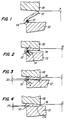
- Figs. 1 - 4 illustrate the process for fusing a lead wire 10 of an armature to a commutator bar 12.
- Wire 10 covered by electrical insulation 14, is passed under a hook 16 on commutator bar 12.
- a high resistance tungsten electrode 18 contacts hook 16 at position A of Fig. 1.
- Electrode 18 applies pressure to hook 16, causing the hook to deform towards commutator bar 12 to form the fused joint.
- a portion of the hook envelops wire 10 (or several wires).
- Electrode 18 deforms hook 16 (see Fig. 4) until a predetermined amount of the front surface 22 of the hook contacts commutator bar 12, and continues to apply current to the hook. The pressure and current are applied until the cohesion joint forms between the contact surface 22 of the hook and the bar. Hook 16 and wire 10 deform further until wire 10 has a predetermined diameter (designated by reference numeral 24).
- the entire (designed) hook surface 22 must be in cohesion contact with the commutator bar to produce a connection with sufficient mechanical resistance to prevent the contact from disconnecting when subjected to high centrifugal forces (high armature speeds). Also, the deformed diameter 24 of wire 10 must be within a predetermined range. This ensures that the mechanical resistance of the wire is acceptable, and that the wire contacts a sufficient hook surface area to give the connection the correct electric resistance. Insulation 14 must be entirely removed from the portion of the wire that contacts the hook surface, to give the connection the correct electrical resistance.
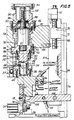
- the armature 26 is firmly mounted and positioned on a stationary work plane 28.
- a conventional angular positioning unit (not shown) typically aligns the commutator hook to be processed with the electrode axis 30.
- a conventional rejecting unit 31 is provided for removing a defective armature from work plane 28.
- Electrode 18 is disposed in electrode axis 30 and directly above hook 16. Electrode 18 is releasably fixed to a supporting block 32.
- Supporting block 32 includes internal passageways 34 for channeling water from a water supply. The water cools the electrode at predetermined rates and intervals.
- Supporting block 32 is rigidly flanged to a first hollow member 36 by screws 38.
- a cylindrical member 40 is seated on the bottom of hollow member 36.
- a force transducer such as a load cell 42, is seated in cylindrical member 40.
- One end of a pin 44 is fixed to hollow member 36, and the other end engages a recess 46 in cylindrical member 40. Pin 44 prevents cylindrical member 40 (and load cell 42) from rotating in respect to hollow member 36.
- Hollow member 36 connects to a second hollow member 48 by a flange 50 and by screws 52. Hollow member 36 is centered and slides on the bottom extension of hollow member 48. A portion of the bottom of hollow member 48 is maintained in contact with a protruding member 54 of load cell 42.
- the apparatus of this invention permits forces acting on hollow member 36 (caused by pressure against electrode 18) to compress load cell 42.
- Hollow member 36 can translate relative to hollow member 48. Spacing 56 between hollow members 36 and 48 permits vertical movement between the two members.
- a roller 57 is fixed to hollow member 36 and runs along supporting block 58. Roller 57 maintains the proper electrode alignment on the electrode axis 30.
- Supporting block 58 surrounds hollow member 48, but is not in contact with it.
- Supporting block 58 is rigidly fixed to a slide 64, which slides on stationary frame guides 66.
- supporting block 58 includes a bar end 68 which is axially fixed, but which is free to rotate in appendix 70 fo supporting block 58.
- a threaded portion of bar 68 engages a threaded block 72, which is fixed to a main frame 74 of the apparatus by a screw 76.
- Slide 64 may be actuated by any suitable actuating means to adjust the electrode rest position to accomodate different commutator sizes.
- a threaded ball sleeve 78 is rigidly fixed to hollow member 48 by a lid 80 and screws 82.
- Ball screw 84 engages threaded sleeve 78 and can be rotated to translate hollow member 48 along electrode axis 30.
- Hollow member 48 includes a bottom cavity 86 that receives the protruding portion of ball screw 84. The sides of cavity 86 do not contact ball screw 84, thus allowing ball screw 84 to rotate relative to hollow member 48. Hollow member 48 will only translate.
- a stud member 88 projects from hollow member 48, and contacts supporting block 58 to prevent hollow member 48 (and hollow member 36) from rotating.
- a connection member 90 is flanged on its bottom end to supporting block 58, and is held in place by screws 92.
- Drive group 94 includes a low inertia dc motor, reduction gear, a tachometer, and an encoder.
- Ball screw shoulder 96 rests against bearing 98, which seats in connection member 90.
- a threaded sleeve 100 connects ball screw 84 to the output drive shaft 102 of the dc motor, and ensures that ball screw 84 is axially positioned against bearing 98.
- a mass electrode 106 is rigidly connected to arm 108, which is hinged to slide 64.
- the rest position of mass electrode 106 may be adjusted to accomodate different commutator sizes by adjusting the position of slide 64.
- An actuator and relative sensing devices move mass electrode 106, causing the electrode to contact the commutator bar to be fused.
- Electric supply cables 110 are connected to block 32 and arm 108. Electrical energy may be applied to electrode 18 as a constant current, and may be integrated in time. Electrical energy may be applied at a predetermined electrode displacement or electrode force.
- a rotation of motor output drive shaft 102 will cause ball screw 84 to rotate. Its engagement with sleeve 100 will cause hollow member 48, hollow member 36, and electrode 18 to translate along electrode axis 30. Ball screw 84 converts the rotational motion of the motor into a translational motion of electrode 18 along axis 30.
- load cell 42 is compressed against hollow member 48. Space 56 allows hollow member 36 to translate along hollow member 48, and will allow load cell 42 to deform correspondingly. In a rest position, or when electrode 18 is moving but is not in contact with hook 16, hollow member 48 is supported by screw heads 112.
- load cell 42 is disposed beneath the commutator support block, on work plane 28. Hollow members 36 and 48 are rigidly connected. Load cell 42 deforms in response to the amount of force exerted on hook 16 when electrode 18 descends upon the hook.
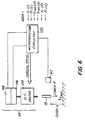
- a motor 114 a tachometer 116, an encoder 118 (which collectively form drive group 94 of Fig. 5), and load cell 42 to a suitable microprocessor-based control circuit 120.
- the measurable quantities include electrode displacement (hook deformation) and electrode pressure.
- the displacement is derived, using encoder 118, from the number of turns of motor drive shaft 102.
- Load cell 42 measures the pressure or force resistance against the electrode.
- the microprocessor and control circuitry store distinct displacement functions X(t) and X(p) and force functions P(x) and P(t), predetermined for each type of hook to be fused.
- Microprocessor 120 changes the field conditions of motor 114 to control the motor torque. Signals received from load cell 42 (indicating electrode pressure) enable the microprocessor to modify the motor torque to satisfy force functions P(x) and P(t). Encoder signals provide microprocessor 120 with displacement information, enabling the microprocessor to precisely lower (or raise) electrode 18 according to the displacement functions X(t) and X(p).
- the feedback loop control transmits the effects of changes made by microprocessor 120 on motor 114 back to the microprocessor, as feedback from load cell 42 and encode 118. The feedback loop control constantly modifies the forces acting on electrode 18 to ensure strict adherence to the proper displacement of force function.
- the apparatus of this invention makes many other measurements and functions possible.
- the electric supply to electrode 18 is selectively variable for predetermined ranges and measured values of electrode displacement or electrode force.
- the measurement feedback loop provides a means for precisely controlling the displacement of electrode 18 throughout the entire fusing cycle.
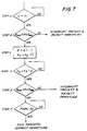
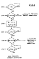
- the measured feedback loop may have two variations: electrode 18 may be displaced as a function of time (fig. 7), or as a function of electrode force (fig. 8).
- the process described in the flowchart of Fig. 7 is used for fusing operations involving small wires or for operations where the final wire deformation must be within very narrow tolerances.
- the measurement feedback control loop monitors the electrode displacement to prevent excessive deformation of wire 10 by excessive electrode displacement. Excessive wire deformation increases the likelihood of wire breakage. The control loop also prevents too little displacement, which would result in a poorly fused wire and a bad electrical connection.
- Step A Motor output drive shaft 102 rotates ball screw 84, causing hollow member 36 and electrode 18 to translate along electrode axis 30 and to approach hook 16 at a predetermined speed.
- the displacement distance X is continuously monitored (step A) by encoder 118 and microprocessor 120.
- step B the electrode force measurement is verified (step B). If the force P acting upon the hook is not within a predetermined range, the process is interrupted and armature 26 is rejected.
- Step B is a quality control step designed to reject an armature with a hook which does not support the desired pressure. For axemple, an armature with a hook formed of poor quality materials, or with a hook that is missing a wire, would not support the pressure and would be rejected.
- Electrode 18 is displaced according to a displacement function X(t) for the type of hook being fused (step C).
- the displacement of electrode 18 is continually monitored (step D) until the electrode reaches a predetermined displacement value which is slightly less than the final displacement.
- load cell 42 again measures the electrode pressure (step E) to determine whether the hook will support a predetermined pressure. If the electrode pressure is not within the predetermined range, microprocessor 120 interrupts the cycle and rejects armature 26. If the electrode pressure is correct, encoder 118 and microprocessor 120 determine whether the displacement of electrode 18 has reached a final predetermined value (step F).
- the final displacement of electrode 18 corresponds to the point at which the electrode is sufficiently displaced to satisfactorily deform wire 10 under hook 16. If electrode 18 has not been sufficiently displaced, the feedback loop waits until the electrode is sufficiently displaced. Excessive electrode displacement will cause armature 26 to be rejected. When electrode 18 has been properly displaced according to step F, the cycle is interrupted, the armature is indexed for operation on the next hook, and the cycle begins again (step A).
- Fig. 8 illustrates the second variation of the measurement feedback loop. Electrode 18 is displaced as a function of the force applied to the electrode. Steps A, B, and D - F of the process typically are the same as the corresponding steps shown in Fig. 7 (i.e., where electrode 18 is displaced as a function of time). However, during step C, electrode 18 is displaced as a function of electrode force.
- Microprocessor 120 receives force data from load cell 42, and acts on motor 114 to adjust electrode displacement according to the predetermined function X(p) for the hook being fused. Electrode displacement is continually monitored (step D) until electrode 18 reaches a predetermined displacement value which is slightly less than the final displacement, after which the process continues as previously described with respect to Fig. 7.
- the force feedback loop provides a means for controlling the electrode pressure throughout the entire work cycle.
- the force feedback loop may have two variations: force may be applied to electrode 18 as a funtion of electrode displacement (Fig. 9), or as a function of time (Fig. 10).
- the process described in the flowchart of Fig. 9 controls the fusion process for wires with larger diameters. Greater tolerances are permitted for the final wire deformation under the hook when fusing large diameter wires than are permitted for thin wires. However, the final pressure values must be within a predetermined range to ensure a satisfactory cohesion joint. This is accomplished with an electrode force feedback control loop and load cell 42.
- Step A Motor output drive shaft 102 rotates ball screw 84, causing hollow member 36 and electrode 18 to translate along electrode axis 30 and to approach hook 16 at a predetermined speed.
- the electrode force P is continuously monitored (step A) by load cell 42 and microprocessor 120.
- step B When electrode displacement X is determined by encoder 118 and microprocessor 120 (step B). If displacement X is not within a predetermined range, the process is interrupted and armature 26 is rejected.
- Step B is a quality control step designed to ensure that electrode 18 is sufficiently displaced to properly contact hook 16 for applying electricity (i.e., there is maximum surface contact between electrode 18 and hook 16). Maximum surface contact between the electrode and the hook results in low current densities through electrode 18, preventing excessive electrode wear.
- step C If the electrode displacement is within the predetermined range, electrical current E is applied to hook 16 via electrode 18. Pressure is applied to electrode 18 as a function of displacement according to a force function P(x) for the hook being fused (step C). A different force function typically is stored in microprocessor circuitry 120 for each type of hook that electrode 18 will deform. The force applied to electrode 18 is continually monitored by load cell 42 and adjusted by the action of microprocessor 120 to maintain the desired pressure as a function of displacement. The force is monitored (step D) until it reaches a final predetermined value P2. When the proper force has been applied, encoder 118 and microprocessor 120 again determine the electrode displacement (step E) to determine whether the force function applied to the hook produced the correct electrode displacement (and hook deformation).
- step A If the electrode displacement is correct, the fusing cycle is interrupted, the armature is indexed for operation on the next hook, and the cycle begins again (step A). If the electrode displacement is not within the predetermined range, the process continues to an additional step (step F). If the electrode displacement exceeds the maximum displacement, the cycle begins again at step C. If the electrode displacement is less than the maximum allowable displacement, microprocessor 120 interrupts the cycle and rejects armature 26.
- Fig. 10 illustrates the second variation of the force feedback loop.
- Force is applied to electrode 18 as a function of time.
- Steps A, B, and D - F of the process typically are the same as the corresponding steps shown in Fig. 9 (i.e. where force is applied to electrode 18 as a function of displacement).
- step C force is applied to electrode 18 as a function of time.
- Microprocessor 120 receives force data from load cell 42, and acts on motor 114 to adjust the electrode force according to the predetermined function P(t) for the hook being fused. Electrode force is continually monitored (step D) until the force reaches a predetermined force value P2, after which the process continues as previously described with respect to Fig. 9.
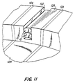
- wires 10 are inserted, generally one on top of the other, in slot 122 with appropriate lead terminating equipment.
- Insulators 124 separate one commutator segment from another.
- the slots are cut in a commutator "ridge" 126.
- the commutator running surface is designated by reference numeral 128.
- Electrode 18 contacts commutator ridge 126, applying pressure to deform the commutator slot around wires 10. It is most important to have a precise electrode displacement when current is applied.
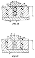
- the optimal displacement X1 (Fig. 12) coincides with maximum surface contact beween electrode 18 and commutator ridge 126.
- Current flowing through electrode 18 generates heat, which initially heats the metal surrounding slot 122, and causes the wire insulation 14 contacting the sides of slot 122 (the slot is usually designed to tightly hold the wires) to vaporize. Electrode 18 exerts force towards the slot bottom, causing plastic deformation of wires 10 and slot 122.
- Fig. 13 shows a final condition of the slot-fusing process, with the metal of slot 122 tightly surrounding the deformed wires 10.
- the final slot deformation X2 (Fig. 13) must be within predetermined tolerances to ensure a proper connection and to ensure that all wires are properly positioned.
- electrode 18 applies force to commutator ridge 126 as a function of displacement, according to a predetermined force function.
- Load cell 42 and microprocessor 120 form a closed loop system to continually monitor and adjust the force applied, according to the force function. Applying force according to the predetermined function ensures that large wires will be tightly surrounded by metal from the walls of slot 122 and ensures that the connection will have the correct mechanical and electrical properties.
- Microprocessor circuitry 120 stores a distinct force function for each slot connection variation (i.e. geometry of the slot, wire size, wire and commutator material, and type of wire insulation).
- the methods and apparatus of the present invention may be used to fuse a stator lead wire 130 to a hook member to the stator 132 of an electric motor.
- Stator hooks are fused in substantially the same manner as commutator hooks.
- Stator hooks may be fused using the same force and displacement feedback loops that are used to fuse commutator hooks 16.
- Fig. 14 shows stator 132, with longitudinal axis 134, wrapped with coils 136 and 138 around poles 140 and 142, respectively. Openings 144 are provided adjacent the lamination stack 146 for receiving and mounting a terminal board 148 against an end face of stack 146. Each of projecting members 150 frictionally engages a terminal 152 for receiving stator lead wire 130 and for providing external lead connections to the stator.
- hook 154 typically is then deformed slightly to hold lead wire 130 in the proper position while stator 132 is transferred to the fusing machine. Hook 154 is formed by cutting a central portion of the body of terminal 152 and bending the central portion upwards.
- Fig. 16 shows stator 132 positioned in a fusing machine between fusing electrode 18 and mass electrode 106. Electrodes 18 and 106 are aligned on a horizontal axis 156. The stator is positioned to align hook 154 in axis 156, between electrodes 18 and 106. The electrodes move along axis 156 to contact hook 154 and to fuse the hook and lead wire 130.
- Each of electrodes 18 and 106 may be moved along axis 156 by independently-controlled drive mechanisms, which typically are equipped with a force transducer and a displacement sensor.
- drive mechanisms typically are equipped with a force transducer and a displacement sensor.
- stator hook 154 can be fused according to a predetermined force or displacement function, using a feedback force or displacement control loop (e.g., as shown in Figs. 7 - 10).
- electric current may be selectively applied to electrode 18 for predetermined values of electrode displacement or force.
- fig. 17 shows the final, fused connection of hook 154 and lead wire 130.
- This simultaneous fusing operation can be performed with a plurality of individual fusing electrodes that are connected to a common drive mechanism, with common displacement and force sensors. The individual electrodes fuse several hooks at the same time.
Landscapes
- Engineering & Computer Science (AREA)
- Manufacturing & Machinery (AREA)
- Power Engineering (AREA)
- Mechanical Engineering (AREA)
- Manufacture Of Motors, Generators (AREA)
- Motor Or Generator Current Collectors (AREA)
- Heat Treatment Of Strip Materials And Filament Materials (AREA)
- Heat Treatment Of Articles (AREA)
- Fuses (AREA)
Claims (13)
- Schmelzvorrichtung zum Verbinden eines Leitungsdrahtes (10) mit einem Anschlußteil (16) eines Ankers oder eines Stators (132) mit einer am Anschlußteil (16) anzusetzenden Elektrode (18) für die Zuführung von elektrischem Strom zum Erwärmen des Anschlußteils (16) und des Leitungsdrahtes (10) in thermischem Kontakt mit der Elektrode (18), und ferner Mittel (94) zum Bewegen der Elektrode (18) mit dem Ziel, das Anschlußteil (16) um den Leitungsdraht (10) unter Ausübung einer Kraft (P) auf das Anschlußteil (16) zu verformen, sowie Mittel (42, 118) zur Überwachung der relativen Verschiebung zwischen der Elektrode (18) und dem Anschlußteil (16),
dadurch gekennzeichnet, daß
die Vorrichtung ferner auf die Mittel zur Registrierung ansprechende Mittel (120) zum Steuern der Bewegungsmittel (94) aufweist, so daß die relative Verschiebung zwischen der Elektrode und dem Anschlußteil einer vorgegebenen Verschiebungsfunktion (X(P), X(t)) gehorcht. - Vorrichtung nach Anspruch 1, wobei die vorgegebene Verschiebungsfunktion eine Funktion (X(t)) zwischen der Verschiebung und der verstrichenen Zeit darstellt.
- Vorrichtung nach Anspruch 1, wobei die Vorrichtung ferner Mittel zur Überwachung der auf das Anschlußteil (16) durch die Elektrode ausgeübten Kraft umfaßt.
- Vorrichtung nach Anspruch 3, wobei die vorgegebene Verschiebungsfunktion eine Funktion (X(P)) zwischen der Verschiebung und der Kraft darstellt.
- Vorrichtung nach Anspruch 1, wobei die Vorrichtung ferner Mittel umfaßt, welche ansprechen auf die Mittel (42, 118) zur Überwachung, um den elektrischen Strom durch die Elektrode (18) und das Anschlußteil (16) fließen zu lassen, wenn eine vorgegebene relative Verschiebung zwischen der Elektrode und dem Anschlußteil aufgetreten ist.
- Vorrichtung nach einem der Ansprüche 1 oder 3, wobei die Vorrichtung ferner Mittel umfaßt, welche ansprechen auf die Mittel zur Steuerung (120) zwecks Unterbrechung der Schmelzvorrichtung und Abweisung des Ankers oder des Stators (132), wenn die Verschiebung zwischen der Elektrode (18) und dem Anschlußteil (16) oder wenn die durch die Elektrode auf das Anschlußteil ausgeübte Kraft mehr als um einen vorgegebenen Betrag von einer vorgegebenen Beziehung abweicht.
- Schmelzverfahren zum Verbinden eines Leitungsdrahtes (10) mit einem Anschlußteil (16) eines Ankers oder eines Stators (132), welches die folgenden Verfahrensschritte umfaßt:gekennzeichnet durch ein Steuern der Bewegung der Elektrode (18) in Reaktion auf den Überwachungsschritt, damit die relative Verschiebung zwischen der Elektrode und dem Anschlußteil einer vorgegebenen Verschiebungsfunktion (X(P), X(t)) entspricht.Ansetzen einer Elektrode (18) am Anschlußteil (16) zum Einleiten von elektrischem Strom zwecks Erwärmens des Anschlußteils (16) und des Leitungsdrahtes (10) in thermischem Kontakt mit der Elektrode (18);Bewegen der Elektrode (18) zum Verformen des Anschlußteils (16) um den Leitungsdraht (10) durch Ausübung einer Kraft (P) auf das Anschlußteil (16);Überwachen der relativen Verschiebung zwischen der Elektrode (18) und dem Anschlußteil (16),
- Verfahren nach Anspruch 7, wobei die vorgegebene Verschiebungsfunktion eine Funktion (X(t)) zwischen der Verschiebung und der verstrichenen Zeit darstellt.
- Verfahren nach Anspruch 7, wobei das Verfahren ferner die Überwachung der durch die Elektrode auf das Anschlußteil (16) ausgeübten Kraft umfaßt.
- Verfahren nach Anspruch 9, wobei die vorgegebene Verschiebungsfunktion eine Funktion (X(P)) zwischen der Verschiebung und der Kraft darstellt.
- Verfahren nach Anspruch 7, wobei das Verfahren den weiteren Verfahrensschritt des Leitens eines elektrischen Stroms durch die Elektrode (18) und das Anschlußteil (16) umfaßt, wenn eine vorgegebene relative Verschiebung zwischen der Elektrode und dem Anschlußteil stattgefunden hat.
- Verfahren nach einem der Ansprüche 7 oder 9, wobei das Verfahren den weiteren Verfahrensschritt des Unterbrechens und Abweisens des Ankers oder des Stators (132) umfaßt, wenn die Verschiebung zwischen der Elektrode (18) und dem Anschlußteil (16) oder die Kraft, die durch die Elektrode auf das Anschlußteil ausgeübt wird, um mehr als einen vorgegebenen Betrag von einer vorgegebenen Beziehung abweicht.
- Verfahren nach Anspruch 7, wobei das Verfahren den weiteren Verfahrensschritt des selektiven Anlegens einer variablen elektrischen Spannung an die Elektrode (18) für vorgegebene Bereiche der relativen Verschiebung (X) umfaßt.
Applications Claiming Priority (5)
| Application Number | Priority Date | Filing Date | Title |
|---|---|---|---|
| US41227989A | 1989-09-25 | 1989-09-25 | |
| US412279 | 1989-09-25 | ||
| US436633 | 1989-11-15 | ||
| US07/436,633 US5063279A (en) | 1989-09-25 | 1989-11-15 | Methods and apparatus for fusing armature and stator wires |
| EP90116084A EP0419849B1 (de) | 1989-09-25 | 1990-08-22 | Verfahren und Vorrichtung zum Verschmelzen von Läufer und Ständerdrähten |
Related Parent Applications (2)
| Application Number | Title | Priority Date | Filing Date |
|---|---|---|---|
| EP90116084.6 Division | 1990-08-22 | ||
| EP90116084A Division EP0419849B1 (de) | 1989-09-25 | 1990-08-22 | Verfahren und Vorrichtung zum Verschmelzen von Läufer und Ständerdrähten |
Publications (3)
| Publication Number | Publication Date |
|---|---|
| EP0584841A2 EP0584841A2 (de) | 1994-03-02 |
| EP0584841A3 EP0584841A3 (en) | 1994-05-18 |
| EP0584841B1 true EP0584841B1 (de) | 1999-06-23 |
Family
ID=27021706
Family Applications (2)
| Application Number | Title | Priority Date | Filing Date |
|---|---|---|---|
| EP93117137A Expired - Lifetime EP0584841B1 (de) | 1989-09-25 | 1990-08-22 | Verfahren und Vorrichtung zum Verschmelzen von Läufer- oder Ständerdrähten |
| EP90116084A Expired - Lifetime EP0419849B1 (de) | 1989-09-25 | 1990-08-22 | Verfahren und Vorrichtung zum Verschmelzen von Läufer und Ständerdrähten |
Family Applications After (1)
| Application Number | Title | Priority Date | Filing Date |
|---|---|---|---|
| EP90116084A Expired - Lifetime EP0419849B1 (de) | 1989-09-25 | 1990-08-22 | Verfahren und Vorrichtung zum Verschmelzen von Läufer und Ständerdrähten |
Country Status (6)
| Country | Link |
|---|---|
| US (1) | US5063279A (de) |
| EP (2) | EP0584841B1 (de) |
| JP (1) | JPH03118747A (de) |
| AT (2) | ATE181523T1 (de) |
| DE (3) | DE69008980T2 (de) |
| ES (1) | ES2056322T3 (de) |
Cited By (2)
| Publication number | Priority date | Publication date | Assignee | Title |
|---|---|---|---|---|
| US9172289B2 (en) | 2012-11-27 | 2015-10-27 | Regal Beloit America, Inc. | Wire guide for use in an electric machine |
| US9698645B2 (en) | 2013-03-14 | 2017-07-04 | Regal Beloit America, Inc. | Electric machine and associated method |
Families Citing this family (29)
| Publication number | Priority date | Publication date | Assignee | Title |
|---|---|---|---|---|
| US5552572A (en) * | 1989-11-30 | 1996-09-03 | Axis Usa, Inc. | Methods and apparatus for identifying hooks of electric motors |
| US5241486A (en) * | 1989-11-30 | 1993-08-31 | Axis U.S.A., Inc. | Methods and apparatus for marking and identifying hooks of electric motors |
| US5122975A (en) * | 1989-11-30 | 1992-06-16 | Axis Usa, Inc. | Methods and apparatus for marking and identifying hooks of electric motors |
| US5386092A (en) * | 1991-11-04 | 1995-01-31 | Unitek Equipment Inc. | Fast response weld head |
| US5300753A (en) * | 1992-06-25 | 1994-04-05 | Axis Usa, Incorporated | Methods and apparatus for fusing electrical conductors |
| US5331130A (en) * | 1992-09-22 | 1994-07-19 | Odawara Automation, Inc. | Method and apparatus for fusing terminal or commutator wire connections on an armature or stator |
| US5360958A (en) * | 1993-05-17 | 1994-11-01 | Delco Electronics Corporation | Welding apparatus having coaxial welding electrodes |
| US5418347A (en) * | 1993-05-19 | 1995-05-23 | Odawara Automation Inc. | Method and apparatus for fusing terminal or commutator wire connections using a trigger current |
| US5504298A (en) * | 1993-06-04 | 1996-04-02 | Axis Usa, Inc. | Methods and apparatus for detecting electrode separation |
| US5484976A (en) * | 1993-10-01 | 1996-01-16 | Axis Usa, Inc. | Fusing methods and apparatus for use in making dynamo-electric machines |
| US5486672A (en) * | 1993-12-13 | 1996-01-23 | Axis Usa, Inc. | Methods and apparatus for commutator fusing |
| US5525774A (en) * | 1994-08-16 | 1996-06-11 | Globe Products Inc. | Method and apparatus for fusing lead wires of coils to terminals |
| FR2728820A1 (fr) * | 1994-12-30 | 1996-07-05 | Renault | Dispositif de soudage par resistance asservi en effort |
| US5660742A (en) * | 1995-03-31 | 1997-08-26 | Joyal Products, Inc. | Insulated wire termination, method, and machine |
| EP0747697A1 (de) | 1995-06-07 | 1996-12-11 | AXIS SpA | Verfahren und Vorrichtung zur akustischen Prüfung von Armaturen |
| US5831235A (en) * | 1996-06-24 | 1998-11-03 | Cecil; Dimitrios G. | Apparatus and method of welding a tube and bracket assembly |
| US5828028A (en) * | 1996-06-24 | 1998-10-27 | Cecil; Dimitrios G. | Hot forging method and apparatus |
| EP0913913B1 (de) | 1997-10-29 | 2003-05-02 | AXIS SpA | Vorrichtung und Verfahren zur Herstellung von Armaturen |
| JP2000126869A (ja) * | 1998-08-20 | 2000-05-09 | Seiwa Seisakusho:Kk | 抵抗溶接装置 |
| US6474435B1 (en) | 2000-09-07 | 2002-11-05 | Trw Vehicle Safety Systems Inc. | Means for electrical connection of components in a vehicle occupant protection system |
| US6911615B2 (en) * | 2000-11-02 | 2005-06-28 | Leander Reischmann | Welding head |
| US6545243B1 (en) * | 2001-09-14 | 2003-04-08 | Delco Remy America, Inc. | Dynamic weld power termination for hot-staking armature commutators |
| US6903298B2 (en) * | 2003-08-25 | 2005-06-07 | General Motors Corporation | Resistance welding control method |
| IT1394587B1 (it) | 2009-04-29 | 2012-07-05 | Atop Spa | Apparecchiatura e metodo per avvolgere e terminare nuclei per macchine dinamo elettriche |
| US20150214820A1 (en) * | 2014-01-24 | 2015-07-30 | Remy Technologies, Llc | Hairpin joint |
| KR102060031B1 (ko) | 2014-07-22 | 2019-12-27 | 어탑 에스.피.에이. | 전기자 코일의 코일 연결부의 전기 저항 결정 방법 및 장치 |
| DE102015000439A1 (de) * | 2015-01-14 | 2016-07-14 | Audi Ag | Verfahren zum Bewickeln eines Wicklungsträgers |
| CN106911232B (zh) * | 2017-04-01 | 2024-04-16 | 宁波韵升电驱动技术有限公司 | 电枢换向器的压制装置及压制方法 |
| CN113458567B (zh) * | 2019-12-10 | 2022-08-26 | 璋祐科技(深圳)有限公司 | 侧顶机构及相应的全自动单侧点焊机 |
Family Cites Families (18)
| Publication number | Priority date | Publication date | Assignee | Title |
|---|---|---|---|---|
| US3045103A (en) * | 1960-10-10 | 1962-07-17 | Warner Samuel | Commutator fusing machine |
| US3449541A (en) * | 1966-01-20 | 1969-06-10 | Martin Marietta Corp | Apparatus for producing resistance welds |
| US3514569A (en) * | 1967-12-28 | 1970-05-26 | Raytheon Co | Resistance welder |
| US3727822A (en) * | 1970-10-05 | 1973-04-17 | Gen Electric | Electromagnetic force system for integrated circuit fabrication |
| US3781981A (en) * | 1972-02-28 | 1974-01-01 | Nippon Denko | Method for making armature-commutator assembly having armature winding of very small diameter |
| DE2538295A1 (de) * | 1975-08-28 | 1977-03-10 | Bosch Gmbh Robert | Verfahren zum herstellen einer elektrisch leitenden und mechanisch festen verbindung von aluminiumleitern an kupferkommutatoren |
| US4079225A (en) * | 1976-08-04 | 1978-03-14 | Warner Allan S | Fiber optic/photon detector for brazing machine |
| US4249068A (en) * | 1978-09-28 | 1981-02-03 | Joyal Products, Inc. | Method and apparatus for controlling heat energy of a bonding transformer |
| US4224496A (en) * | 1978-10-12 | 1980-09-23 | Joyal Products, Inc. | Method and apparatus for controlling a brazing machine |
| DE3018384A1 (de) * | 1980-05-14 | 1981-11-19 | Rossell Electronique S.A., Lausanne | Verfahren zum zubringen von mindestens einer elektrode, zubringevorrichtung und aufnehmer zur ausfuehrung dieses verfahrens sowie verwendung des verfahrens, der zubringevorrichtung und/oder des aufnehmers |
| US4451722A (en) * | 1980-11-03 | 1984-05-29 | Joyal Products, Inc. | Fusing machine |
| US4371772A (en) * | 1980-11-03 | 1983-02-01 | Joyal Products, Inc. | Plural shaft electrode support for fusing machine |
| US4510370A (en) * | 1980-11-03 | 1985-04-09 | Joyal Products, Inc. | Fusing machine |
| US4504724A (en) * | 1980-11-03 | 1985-03-12 | Joyal Products, Inc. | Fusing machine |
| JPS5822861U (ja) * | 1981-07-31 | 1983-02-12 | マブチモ−タ−株式会社 | 小型モ−タの整流子装置 |
| US4419558A (en) * | 1981-11-23 | 1983-12-06 | Wagen Of America, Inc. | Apparatus and method for monitoring and controlling resistance spot welding |
| US4562330A (en) * | 1983-09-09 | 1985-12-31 | Digimetrics, Inc. | Spot weld quality monitoring system |
| DE3711771A1 (de) * | 1987-04-08 | 1988-10-27 | Sts Systemtechnik Und Software | Verfahren und einrichtung fuer die prozessreglung beim punktschweissen |
-
1989
- 1989-11-15 US US07/436,633 patent/US5063279A/en not_active Expired - Lifetime
-
1990
- 1990-08-22 AT AT93117137T patent/ATE181523T1/de not_active IP Right Cessation
- 1990-08-22 DE DE69008980T patent/DE69008980T2/de not_active Expired - Lifetime
- 1990-08-22 AT AT90116084T patent/ATE105755T1/de not_active IP Right Cessation
- 1990-08-22 DE DE199090116084T patent/DE419849T1/de active Pending
- 1990-08-22 DE DE69033184T patent/DE69033184T2/de not_active Expired - Lifetime
- 1990-08-22 EP EP93117137A patent/EP0584841B1/de not_active Expired - Lifetime
- 1990-08-22 EP EP90116084A patent/EP0419849B1/de not_active Expired - Lifetime
- 1990-08-22 ES ES90116084T patent/ES2056322T3/es not_active Expired - Lifetime
- 1990-09-25 JP JP2256776A patent/JPH03118747A/ja active Pending
Cited By (2)
| Publication number | Priority date | Publication date | Assignee | Title |
|---|---|---|---|---|
| US9172289B2 (en) | 2012-11-27 | 2015-10-27 | Regal Beloit America, Inc. | Wire guide for use in an electric machine |
| US9698645B2 (en) | 2013-03-14 | 2017-07-04 | Regal Beloit America, Inc. | Electric machine and associated method |
Also Published As
| Publication number | Publication date |
|---|---|
| ES2056322T3 (es) | 1994-10-01 |
| DE69033184T2 (de) | 2000-03-09 |
| ATE181523T1 (de) | 1999-07-15 |
| JPH03118747A (ja) | 1991-05-21 |
| DE419849T1 (de) | 1993-11-04 |
| EP0584841A3 (en) | 1994-05-18 |
| ATE105755T1 (de) | 1994-06-15 |
| US5063279A (en) | 1991-11-05 |
| DE69008980T2 (de) | 1994-09-08 |
| EP0419849A1 (de) | 1991-04-03 |
| EP0584841A2 (de) | 1994-03-02 |
| DE69008980D1 (de) | 1994-06-23 |
| DE69033184D1 (de) | 1999-07-29 |
| EP0419849B1 (de) | 1994-05-18 |
Similar Documents
| Publication | Publication Date | Title |
|---|---|---|
| EP0584841B1 (de) | Verfahren und Vorrichtung zum Verschmelzen von Läufer- oder Ständerdrähten | |
| EP0397434B1 (de) | Verfahren und Vorrichtung zur Verbindung eines Drahtes an einer Anschlussklemme | |
| US5300753A (en) | Methods and apparatus for fusing electrical conductors | |
| USRE30001E (en) | Methods and apparatus for making electrical interconnections | |
| US5122975A (en) | Methods and apparatus for marking and identifying hooks of electric motors | |
| US5317125A (en) | Fusing apparatus with temperature control | |
| CN1034963C (zh) | 在织机中自动控制经纱张力的改进设备 | |
| US5478982A (en) | Apparatus for fusing terminal or commutator wire connections on an armature or stator | |
| US5241486A (en) | Methods and apparatus for marking and identifying hooks of electric motors | |
| US20060198915A1 (en) | Method and device for quality assurance of crimp joints | |
| US5153404A (en) | Fusing apparatus and method using concave shaped electrodes | |
| US4687900A (en) | Fusing methods and apparatus therefor | |
| US5552572A (en) | Methods and apparatus for identifying hooks of electric motors | |
| US5486672A (en) | Methods and apparatus for commutator fusing | |
| JP2000114086A (ja) | コイル巻線装置 | |
| JP4270558B2 (ja) | 通電熱カシメ接合装置 | |
| EP0629028A2 (de) | Geräte und Verfahren zum Markieren und Erkennen von Kollektorhaken in elektrischen Motoren | |
| JPH04137516A (ja) | マグネットワイヤとリード線の接続方法及び接続装置 | |
| JPH06218700A (ja) | 導線の切断方法及びコイル部品 | |
| JPH10125513A (ja) | 電流検出用抵抗器の製造装置 | |
| JP4639765B2 (ja) | ワニス含浸装置及びワニス含浸方法 | |
| JP3090395B2 (ja) | 電気半田ごて装置 | |
| CN210154535U (zh) | 一种接触器铁芯行程间隙测试机构 | |
| JPS6030544A (ja) | 塑性加工法およびその装置 | |
| EP0627796A2 (de) | Geräte und Verfahren zur Feststellung des Trennens einer Elektrode |
Legal Events
| Date | Code | Title | Description |
|---|---|---|---|
| PUAI | Public reference made under article 153(3) epc to a published international application that has entered the european phase |
Free format text: ORIGINAL CODE: 0009012 |
|
| AC | Divisional application: reference to earlier application |
Ref document number: 419849 Country of ref document: EP |
|
| AK | Designated contracting states |
Kind code of ref document: A2 Designated state(s): AT BE CH DE ES FR GB IT LI NL SE |
|
| PUAL | Search report despatched |
Free format text: ORIGINAL CODE: 0009013 |
|
| AK | Designated contracting states |
Kind code of ref document: A3 Designated state(s): AT BE CH DE ES FR GB IT LI NL SE |
|
| 17P | Request for examination filed |
Effective date: 19941108 |
|
| 17Q | First examination report despatched |
Effective date: 19970522 |
|
| GRAG | Despatch of communication of intention to grant |
Free format text: ORIGINAL CODE: EPIDOS AGRA |
|
| GRAG | Despatch of communication of intention to grant |
Free format text: ORIGINAL CODE: EPIDOS AGRA |
|
| GRAG | Despatch of communication of intention to grant |
Free format text: ORIGINAL CODE: EPIDOS AGRA |
|
| GRAH | Despatch of communication of intention to grant a patent |
Free format text: ORIGINAL CODE: EPIDOS IGRA |
|
| RAP1 | Party data changed (applicant data changed or rights of an application transferred) |
Owner name: AXIS S.P.A. |
|
| GRAH | Despatch of communication of intention to grant a patent |
Free format text: ORIGINAL CODE: EPIDOS IGRA |
|
| GRAH | Despatch of communication of intention to grant a patent |
Free format text: ORIGINAL CODE: EPIDOS IGRA |
|
| GRAA | (expected) grant |
Free format text: ORIGINAL CODE: 0009210 |
|
| AC | Divisional application: reference to earlier application |
Ref document number: 419849 Country of ref document: EP |
|
| AK | Designated contracting states |
Kind code of ref document: B1 Designated state(s): AT BE CH DE ES FR GB IT LI NL SE |
|
| PG25 | Lapsed in a contracting state [announced via postgrant information from national office to epo] |
Ref country code: SE Free format text: THE PATENT HAS BEEN ANNULLED BY A DECISION OF A NATIONAL AUTHORITY Effective date: 19990623 Ref country code: NL Free format text: LAPSE BECAUSE OF FAILURE TO SUBMIT A TRANSLATION OF THE DESCRIPTION OR TO PAY THE FEE WITHIN THE PRESCRIBED TIME-LIMIT Effective date: 19990623 Ref country code: ES Free format text: THE PATENT HAS BEEN ANNULLED BY A DECISION OF A NATIONAL AUTHORITY Effective date: 19990623 Ref country code: BE Free format text: LAPSE BECAUSE OF FAILURE TO SUBMIT A TRANSLATION OF THE DESCRIPTION OR TO PAY THE FEE WITHIN THE PRESCRIBED TIME-LIMIT Effective date: 19990623 Ref country code: AT Free format text: LAPSE BECAUSE OF FAILURE TO SUBMIT A TRANSLATION OF THE DESCRIPTION OR TO PAY THE FEE WITHIN THE PRESCRIBED TIME-LIMIT Effective date: 19990623 |
|
| REF | Corresponds to: |
Ref document number: 181523 Country of ref document: AT Date of ref document: 19990715 Kind code of ref document: T |
|
| REG | Reference to a national code |
Ref country code: CH Ref legal event code: EP |
|
| REF | Corresponds to: |
Ref document number: 69033184 Country of ref document: DE Date of ref document: 19990729 |
|
| ET | Fr: translation filed | ||
| ITF | It: translation for a ep patent filed | ||
| REG | Reference to a national code |
Ref country code: CH Ref legal event code: NV Representative=s name: ISLER & PEDRAZZINI AG |
|
| NLV1 | Nl: lapsed or annulled due to failure to fulfill the requirements of art. 29p and 29m of the patents act | ||
| PLBQ | Unpublished change to opponent data |
Free format text: ORIGINAL CODE: EPIDOS OPPO |
|
| PLBI | Opposition filed |
Free format text: ORIGINAL CODE: 0009260 |
|
| PLBF | Reply of patent proprietor to notice(s) of opposition |
Free format text: ORIGINAL CODE: EPIDOS OBSO |
|
| 26 | Opposition filed |
Opponent name: ATOP S.P.A. Effective date: 20000323 |
|
| PLBF | Reply of patent proprietor to notice(s) of opposition |
Free format text: ORIGINAL CODE: EPIDOS OBSO |
|
| PLBF | Reply of patent proprietor to notice(s) of opposition |
Free format text: ORIGINAL CODE: EPIDOS OBSO |
|
| REG | Reference to a national code |
Ref country code: GB Ref legal event code: IF02 |
|
| PLBO | Opposition rejected |
Free format text: ORIGINAL CODE: EPIDOS REJO |
|
| APAC | Appeal dossier modified |
Free format text: ORIGINAL CODE: EPIDOS NOAPO |
|
| APAC | Appeal dossier modified |
Free format text: ORIGINAL CODE: EPIDOS NOAPO |
|
| APAC | Appeal dossier modified |
Free format text: ORIGINAL CODE: EPIDOS NOAPO |
|
| APAA | Appeal reference recorded |
Free format text: ORIGINAL CODE: EPIDOS REFN |
|
| PGFP | Annual fee paid to national office [announced via postgrant information from national office to epo] |
Ref country code: GB Payment date: 20050805 Year of fee payment: 16 |
|
| APAH | Appeal reference modified |
Free format text: ORIGINAL CODE: EPIDOSCREFNO |
|
| APBU | Appeal procedure closed |
Free format text: ORIGINAL CODE: EPIDOSNNOA9O |
|
| PLBN | Opposition rejected |
Free format text: ORIGINAL CODE: 0009273 |
|
| STAA | Information on the status of an ep patent application or granted ep patent |
Free format text: STATUS: OPPOSITION REJECTED |
|
| 27O | Opposition rejected |
Effective date: 20060228 |
|
| GBPC | Gb: european patent ceased through non-payment of renewal fee |
Effective date: 20060822 |
|
| REG | Reference to a national code |
Ref country code: CH Ref legal event code: PCAR Free format text: ISLER & PEDRAZZINI AG;POSTFACH 1772;8027 ZUERICH (CH) |
|
| PG25 | Lapsed in a contracting state [announced via postgrant information from national office to epo] |
Ref country code: GB Free format text: LAPSE BECAUSE OF NON-PAYMENT OF DUE FEES Effective date: 20060822 |
|
| PGFP | Annual fee paid to national office [announced via postgrant information from national office to epo] |
Ref country code: FR Payment date: 20090819 Year of fee payment: 20 |
|
| PGFP | Annual fee paid to national office [announced via postgrant information from national office to epo] |
Ref country code: CH Payment date: 20090824 Year of fee payment: 20 |
|
| PGFP | Annual fee paid to national office [announced via postgrant information from national office to epo] |
Ref country code: DE Payment date: 20091026 Year of fee payment: 20 |
|
| REG | Reference to a national code |
Ref country code: CH Ref legal event code: PL |
|
| PG25 | Lapsed in a contracting state [announced via postgrant information from national office to epo] |
Ref country code: IT Free format text: LAPSE BECAUSE OF NON-PAYMENT OF DUE FEES Effective date: 20090822 |
|
| PGFP | Annual fee paid to national office [announced via postgrant information from national office to epo] |
Ref country code: IT Payment date: 20090803 Year of fee payment: 20 |
|
| PGRI | Patent reinstated in contracting state [announced from national office to epo] |
Ref country code: IT Effective date: 20110616 |
|
| PG25 | Lapsed in a contracting state [announced via postgrant information from national office to epo] |
Ref country code: DE Free format text: LAPSE BECAUSE OF EXPIRATION OF PROTECTION Effective date: 20100822 |