EP0584932A1 - Connecteur autopositionnent pour lecteur de disquette - Google Patents
Connecteur autopositionnent pour lecteur de disquette Download PDFInfo
- Publication number
- EP0584932A1 EP0584932A1 EP93305699A EP93305699A EP0584932A1 EP 0584932 A1 EP0584932 A1 EP 0584932A1 EP 93305699 A EP93305699 A EP 93305699A EP 93305699 A EP93305699 A EP 93305699A EP 0584932 A1 EP0584932 A1 EP 0584932A1
- Authority
- EP
- European Patent Office
- Prior art keywords
- guide housing
- guide
- circuit board
- modular component
- camming
- Prior art date
- Legal status (The legal status is an assumption and is not a legal conclusion. Google has not performed a legal analysis and makes no representation as to the accuracy of the status listed.)
- Ceased
Links
Images













Classifications
-
- G—PHYSICS
- G11—INFORMATION STORAGE
- G11B—INFORMATION STORAGE BASED ON RELATIVE MOVEMENT BETWEEN RECORD CARRIER AND TRANSDUCER
- G11B33/00—Constructional parts, details or accessories not provided for in the other groups of this subclass
- G11B33/12—Disposition of constructional parts in the apparatus, e.g. of power supply, of modules
- G11B33/121—Disposition of constructional parts in the apparatus, e.g. of power supply, of modules the apparatus comprising a single recording/reproducing device
- G11B33/122—Arrangements for providing electrical connections, e.g. connectors, cables, switches
-
- H—ELECTRICITY
- H01—ELECTRIC ELEMENTS
- H01R—ELECTRICALLY-CONDUCTIVE CONNECTIONS; STRUCTURAL ASSOCIATIONS OF A PLURALITY OF MUTUALLY-INSULATED ELECTRICAL CONNECTING ELEMENTS; COUPLING DEVICES; CURRENT COLLECTORS
- H01R12/00—Structural associations of a plurality of mutually-insulated electrical connecting elements, specially adapted for printed circuits, e.g. printed circuit boards [PCB], flat or ribbon cables, or like generally planar structures, e.g. terminal strips, terminal blocks; Coupling devices specially adapted for printed circuits, flat or ribbon cables, or like generally planar structures; Terminals specially adapted for contact with, or insertion into, printed circuits, flat or ribbon cables, or like generally planar structures
- H01R12/70—Coupling devices
- H01R12/71—Coupling devices for rigid printing circuits or like structures
- H01R12/72—Coupling devices for rigid printing circuits or like structures coupling with the edge of the rigid printed circuits or like structures
- H01R12/721—Coupling devices for rigid printing circuits or like structures coupling with the edge of the rigid printed circuits or like structures cooperating directly with the edge of the rigid printed circuits
-
- H—ELECTRICITY
- H01—ELECTRIC ELEMENTS
- H01R—ELECTRICALLY-CONDUCTIVE CONNECTIONS; STRUCTURAL ASSOCIATIONS OF A PLURALITY OF MUTUALLY-INSULATED ELECTRICAL CONNECTING ELEMENTS; COUPLING DEVICES; CURRENT COLLECTORS
- H01R12/00—Structural associations of a plurality of mutually-insulated electrical connecting elements, specially adapted for printed circuits, e.g. printed circuit boards [PCB], flat or ribbon cables, or like generally planar structures, e.g. terminal strips, terminal blocks; Coupling devices specially adapted for printed circuits, flat or ribbon cables, or like generally planar structures; Terminals specially adapted for contact with, or insertion into, printed circuits, flat or ribbon cables, or like generally planar structures
- H01R12/70—Coupling devices
- H01R12/82—Coupling devices connected with low or zero insertion force
-
- Y—GENERAL TAGGING OF NEW TECHNOLOGICAL DEVELOPMENTS; GENERAL TAGGING OF CROSS-SECTIONAL TECHNOLOGIES SPANNING OVER SEVERAL SECTIONS OF THE IPC; TECHNICAL SUBJECTS COVERED BY FORMER USPC CROSS-REFERENCE ART COLLECTIONS [XRACs] AND DIGESTS
- Y10—TECHNICAL SUBJECTS COVERED BY FORMER USPC
- Y10S—TECHNICAL SUBJECTS COVERED BY FORMER USPC CROSS-REFERENCE ART COLLECTIONS [XRACs] AND DIGESTS
- Y10S439/00—Electrical connectors
- Y10S439/933—Special insulation
- Y10S439/936—Potting material or coating, e.g. grease, insulative coating, sealant or, adhesive
Definitions
- U.S. Patent Nos. 4,969,824 and 5,061,191 address the foregoing problems by employing a flexible printed circuit film strip with contact pads for electrically contacting an adjoining circuit board, and an underlying housing containing elongated coil springs which press the film strips and their contact pads against the appropriate point on the printed circuit board.
- the coil springs disclosed therein facilitate a high density array of stable low-resistance electrical contacts.
- an object of the present invention to provide a docking connector for electrically and mechanically connecting a modular component such as a disk drive to a circuit board.
- the present invention provides a docking connector for mechanically interfacing a circuit board and a modular component such as a disk drive.
- the docking connector includes a guide housing formed as an openended enclosure.
- the enclosure has a first end for slidable insertion of the modular component, and a second end for slidable insertion of the edge of the circuit board.
- the guide housing further includes interior alignment means for guiding insertion of the modular component such that its contact terminals are brought into a facing spaced-apart relation with the appropriate traces along the circuit board edge.
- the connector also includes a camming assembly which is pivoted at the first end of the guide housing for manipulating the modular component to thereby bring its contact terminals into electrical contact with the traces of the circuit board, thereby completing an electrical interface between the circuit board and the modular component.
- the invention also encompasses an interfacing connector for providing an electrical as well as a mechanical interface between a circuit board and a modular component such as a disk drive.
- the interfacing connector includes a connector housing having a first ingress for insertion of a printed circuit board, a second ingress to allow coupling of a modular component, and a transverse support shelf extending between the first ingress and second ingress.
- a plurality of conductive terminals are arranged within the second ingress of the connector housing along the shelf for completing a multiple-electrical-connection interface with the modular component.
- a plurality of canted coil springs are arranged linearly within the first ingress of the connector housing along the shelf. Each spring is connected to a corresponding one of the conductive terminals.
- the interfacing connector may be connected at the second ingress to the disk drive, and the circuit board may be inserted into the open first ingress of said connector housing along the shelf to bring the canted coil springs into conductive contact at an appropriate point on the circuit board. In this manner, an electrical interface is completed between the circuit board and the disk drive.
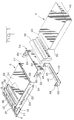
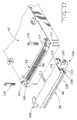
- a guide housing 2 is formed of sheet metal or the like into a basically rectangular box-like structure.
- Guide housing 2 serves to linearly guide a modular component such as a conventional hard disk drive 4 into engagement with a fixed printed circuit mother board 6.
- Housing 2 has a pair of outwardly directed mounting ears 8 at an end facing the mother board 6 for rigid connection to the mother board via mounting fasteners 10. This absolutely locates the guide housing 2 relative to the circuit traces on the mother board.
- the housing 2 could also be secured to the floor of the computer housing as shown in Figure 4.
- Housing 2 on the same end as the mounting ears 8, also contains a protective cover 12 which is fixed for rotation about a pivot pin 14, pin 14 in turn being mounted between supporting ears 16 which extend from the sidewalls of housing 2.
- This cover 12 by force of gravity, overlies the contact area of the mother board and its associated compressive members (which, for example, may be canted coiled springs, ampliflex or any other type compressive connector).
- the cover 12 may contain a felt insert 18 saturated with a cleaning solvent to maintain clean contacts. Either way, the cover 12 will protect the contact surfaces from dust contamination.
- the cover 12 Upon insertion of a device 4, the cover 12 is lifted upwardly by the printed circuit board 20 of the device to permit the board 20 to come in between the cover 12 and the mother board 6 for subsequent interconnection therewith. (See Figures 4-10.)
- the guide housing 2 is dimensioned across its width to receive and guide the device 4 linearly.
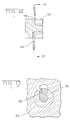
- a detent 22 in each sidewall 24 aids in maintaining the device 4 in linear alignment.
- Means for controlling the vertical movement of the device 4 is also provided in the guide housing 2.
- a rigid protrusion 26 is bent up from the floor 28 of the housing 2 to engage the lower leading edge 30 of the device 4 to urge said device in an upward direction when it reaches that position during its insertion.
- the device 4 is urged upwardly against a compliant guide 32 which is formed inwardly from the top 34 of the housing 2.
- This guide has a free end 36 to permit it to flexibly urge the device 4 in a downwardly direction but yielding to the rigid guide 26.
- the two guides 26 and 32 cause the printed circuit board end of the device to raise to a position of clearance relative to the mother board 6 during its insertion.
- the compliant guide 32 also supplies the downward force needed when the device is raised on its rear end by the closing of the door 38.
- Lifter 40 has a floor area 42 with a linear embossment 44 which engages the bottom of the end 46 of the device 4. (See Figure 3).
- a pair of upstanding walls 48 extend from the floor 42 and contain fixed pins 50 for engagement in a cam track 52 on a member 54 which is rigidly mounted to the door 38.
- Camming member 54 and door 38 are pivotally connected to the sidewalls 24 of housing 2 via pivot pins 56 (see Figures 4-8) fixed for rotation in holes 58 in housing 2 and holes 60 in a camming member 54.
- a standard computer housing 62 is shown in cross-section, said section being substantially through the center of the housing 2 and mother board 6.
- Mother board 6 is fixed in the housing 62 via stand-off mounts 64 extending upwardly from the floor 66 of housing 62.
- Guide housing 2 is fixed to the mother board as described above in reference to mounting ears 8 and to the floor 66 by suitable fasteners.
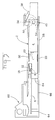
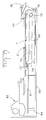
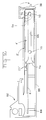
- Figure 4 shows the device 4 entering guide housing 2 through the opened door 38.
- Cam track 52 is holding the pins 50 and thereby the lifter 40 in a downward position. This position is maintained through Figure 7.
- Figure 5 shows the device 4 sliding along the floor 28 of housing 2 and just prior to its contact with the fixed guide 26. If the device 4 was permitted to continue in this trajectory, it would collide with the leading edge of the mother board 6 and would most likely rip apart the compressive contact members on the board.
- the rigid guide 26 urges the device upwardly against the compliant guide 32 to cause it to clear the mother board and its contacts upon further insertion.
- the protective cover 12 is also at this point caused to rotate clockwise to expose the mother board's contact elements.
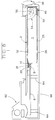
- Figure 7 shows the device 4 completely inserted but still held away from contact with the mother board. (See also Figure 9.) Upon closure of the door 38, the rear end of the device is raised as described above and as seen in Figures 8 and 10 to thereby lower the opposite end of the device into electrical engagement with the mother board 6.
- opening the door 38 will lower the lifter 40 and thereby the rear end of the device 4 to place the device back to the position of Figures 7 and 9 with electrical contact broken.
- the device can then be retracted from the computer to be stored or to be replaced by another device containing different software.
- a plurality of devices can thereby be used interchangeably within a computer equipped with the guide means of this disclosure.
- the guide housing 2' is similar in construction to the previously described housing 2 except for the vertical guide means.
- the hard disk drive device 4' is made with a guiding channel 68 on each side for cooperation with a pair of fixed guide pins 70 on the mother board end of the housing 2' and a pair of movable guide pins 72 on the opposite end.
- the guide pins 70 and 72 extend inside the housing 2' to engage in the channels 68 on the device 4' to control the movement thereof.
- Each channel 68 has a bell-mouthed entry portion 74 to ensure proper contact with the guide pins and an abrupt end 76 on the rear end to serve as a positive stop upon insertion.
- Housing 2' has mounting features and a protective cover similar to the previously described housing 2.
- the movable pins 72 are mounted in slots 78 in the sidewalls 24' of housing 2'.
- the construction of the pins 72 is shown in Figures 12 and 13. As can be seen in these figures, the pin has a limited amount of guided vertical movement in the slot 78.
- the camming member 54 and door 38 are the same as in the previous embodiment.
- the movable pin 72 is held in a downward position by camming member 54 to hold the rear end of the device 4' in a lowered position.
- the device slides along the floor of the guide housing 2' as it is inserted until the bell-mouthed portion 74 of the channel 68 picks up the fixed guide pin 70 at which time the nose of the device is urged upwardly by the pin. This upward movement causes the printed circuit board 20' of the device 4' to clear the end of the mother board as previously described.
- Figure 15 shows the device 4' fully inserted but not electrically connected to the mother board 6 due to the lowered position of the movable guide pin 72.
- the camming member 54 raises the movable pin 72 in its slot 78 and thereby raises the rear end of the device 4' which pivots counterclockwise about the fixed pin 70 to make electrical contact with the mother board.
- removal of the device is accomplished by opening door 38 which breaks the electrical contact with the mother board and permits the drive to be withdrawn with no possibility of damaging the mother board or its compressive contact members.
- the above-described embodiments of the invention facilitate the connecting of a mother board directly to a modular device by a mechanical docking assembly.
- the compressive contact members are shown to be mounted on the circuit board.
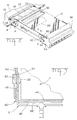
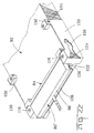
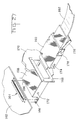
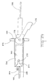
- Figure 17 shows an interfacing connector 80 in alignment with a standard disk drive 82. These drives are supplied with a pin connector 84 having two rows of pins 86 and which is permanently affixed to the disk drive.
- Connector 80 contains two rows of sockets 90 ( Figures 19 and 20) for receiving pins 86 to interconnect them to a flexible etched circuit 88 which is fixed to the under surface 92 of the connector 80 and which contains a single row of contact pads 94 connected via traces 96 to two rows of pads on the socket side of the connector ( Figure 19).
- the sockets 90 are soldered to these pads to cause electrical continuity from the hard drive pins 86 to the row of contact pads 94 on the underside of the connector projection 98.
- the compressive contact members in this embodiment are canted coiled springs 100 (one for each pad 94) which are retained in a strip 102 of plastic material.
- Strip 102 has a plurality of holes 104 in alignment with protruding pins 106 on housing projection 98 and is heat staked to the connector to retain the canted coil springs 100 in proper alignment with their respective contact pads 94.
- the strip 102 also serves to secure the flexible etched circuit 88 to the connector.
- the connector 80 must be rigidly fixed to the disk drive to withstand contact forces and to avoid damaging the pins 86.
- the connector has extended ends 108 configured to straddle an existing ledge 110 on each side of the disk drive 82 and a protruding ear 112 which is received by a cavity 114 in the ends of the existing pin connector 84 (see Figure 18).
- a fastener 116 is inserted through the hole 118 in the end 108 and extends through the disk drive ledge 110 and is secured in the lower portion 120 of end 108. This rigidly connects the connector 80 to the disk drive 82 to make them, effectively, one piece.
- a lower extension 122 is provided on connector 80 to add mounting support and to provide a pivot means 124 about which a protective cover 126 rotates.
- Cover 126 is spring loaded into light engagement with the row of canted coil springs 100 to protect the springs and the FEC when the connector is disengaged from a computer.
- the protruding end 128 of cover 126 is contoured to be easily pushed open by the mother board when the connector and the disk drive are inserted into the computer.
- the disk drive and connector 80 are guided into the computer in the same manner as the previously described embodiments.
- the major difference in these embodiments is the location of the compressible contact members.
- Figures 21 and 22 illustrate a further embodiment of the interfacing connector.
- Connector 80' has additional side extensions 130 which add to the rigidity of the assembly by extending back to existing mounting features 132 on the disk drive 82 and being attached to them by screws 134.
- extensions 130 may contain a cam track 136 to be engaged by a fixed guide pin in a guide housing similar to housing 2'. This would eliminate the need for a lifting feature on the guide housing since vertical movement would be controlled by the cam traces 136 as it passes over the fixed guide pin (not shown).
- FIG. 23 and 24 A further embodiment of an interfacing connector is illustrated in Figures 23 and 24.
- This connector 80'' is similar to connector 80 with the exception of the compressive contact area.
- a single canted coiled spring 138 supplies the compressive force for the entire row of contact pads 140.
- the spring 138 lies in a channel 142 in the connector projection 144 beneath the flexible etched circuitry 146 to urge said circuitry against the mother board pads to effect electrical contact therewith.
- FIG. 25 and 26 A still further embodiment of an interfacing connector is shown in Figures 25 and 26.
- the contact portion of this connector 80′′′ is the same as that shown in connector 80'' but the lower portion 148 is configured to provide a camming surface 150 having a beveled lead-in 152 on its forward end.
- This camming surface cooperates with an activating cam 154 which is formed in the guide housing (not shown but similar to 2 and 2').
- Cam 154 is located directly under the mother board 6 and could be a simple wedge-shaped separate piece attached to the bottom of the mother board 6.
- a light spring (not shown) formed up from the floor of the guide housing, urges the nose of the device upwardly to clear the mother board as previously described.
- cam lead in 152 and subsequently 150 are picked up by the leading end of the angled cam face 154 to force the drive and connector downwardly to engage the circuit pads on mother board 6 (see Figure 26).
- This connector also has a protective cover 156 which is forced open by the board 6 and cam 154 upon insertion of the device in a similar manner as the aforementioned embodiments. This connector eliminates the need for separate guide members to be built into the guide housing.
- Figures 27-34 illustrate how the invention may be used for any type device including a cabled connector wherein it is desired to dock the device to another device in a manner which allows the use of relatively fragile compressive contact members. To date, it has been difficult to make such a docking connection to another device because the straight line sliding insertion of a device would destroy the compressive contact member.
- the guide housing 2 as being made of formed sheet metal, but it is to be understood that this housing could also be made of any suitable material. It could also be a molded plastic unit or even be designed and molded directly as an integral part of a device housing.
- Figure 27 shows a guide housing 158 made to cooperate with a coiled connector 160 which is to be docked to a printed circuit board 162.
- the compressible contact member 164 in this case is an elastomeric type produced by AMP Incorporated and known as AMPLIFLEX, but obviously, any type compressible member could be used.
- Housing 158 has formed mounting ears 166 to attach to the circuit board 162 and on its opposite end, a mounting flange 168 for rigid mounting to a device housing 170.
- a fixed pivot pin 172 is formed inwardly from the sidewalls of housing 158 to cooperate with a guide slot 174 in connector 160 to provide the aforementioned up and down motion of the connector during docking.
- a camming lever 176 to provide the upward motion of that end of the connector (after the connector has been fully inserted) to cause electrical contact between the circuit board 162 and the inserted connector.
- FIGs 31-33 illustrate the construction of a typical passive connector.
- a molded housing 180 has the outside profile described above and in this case is configured to receive a flat ribbon cable or flexible etched circuit 182 and to electrically connect said cable or circuit to a small printed circuit board 184 having standard circuit traces and pads on its underside.
- An elastomeric interface connector 186 is used to make this connection.
- a strain relief member 188 snap fits on the back end of housing 180 to retain the cable or circuit. Electrical connection of PCB 184 to cable or circuit 182 is effected when the assembly is bolted together with bolts 190 and nuts 192 as seen in Figures 32 and 33. It is to be understood that other types of compressible interfaces could also be used to serve the same function as member 186.
- PCB 184 has a forwardly extending portion 194 with circuit pads on its underside for mating in docking relationship with circuit board 162.
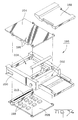
- FIG 34 illustrates the construction of a docking connector 196 made to carry active components 198 in addition to interconnecting the aforementioned cable or circuit 182.
- a housing 200 has an outward profile similar to that previously described and a cable receiving and retaining area 202 for termination of said cable or circuit to a PCB 204 which carries, in addition to its circuitry, active elements 198 on its underside.
- the housing 200 has an internal cavity 206 to receive said elements when the components are assembled.
- a second PCB 208 can also be employed on the opposite side of connector 200 if additional circuitry or components are needed. Interconnection of printed circuit boards 204 and 208 is accomplished through a compressible interface member 210. This type connector could be used to house a modem, for example, or any other desired circuitry.
Landscapes
- Coupling Device And Connection With Printed Circuit (AREA)
Applications Claiming Priority (2)
| Application Number | Priority Date | Filing Date | Title |
|---|---|---|---|
| US07/929,185 US5211566A (en) | 1992-08-11 | 1992-08-11 | Docking connector for disk drives |
| US929185 | 1992-08-11 |
Publications (1)
| Publication Number | Publication Date |
|---|---|
| EP0584932A1 true EP0584932A1 (fr) | 1994-03-02 |
Family
ID=25457446
Family Applications (1)
| Application Number | Title | Priority Date | Filing Date |
|---|---|---|---|
| EP93305699A Ceased EP0584932A1 (fr) | 1992-08-11 | 1993-07-20 | Connecteur autopositionnent pour lecteur de disquette |
Country Status (3)
| Country | Link |
|---|---|
| US (1) | US5211566A (fr) |
| EP (1) | EP0584932A1 (fr) |
| JP (1) | JPH06168062A (fr) |
Families Citing this family (27)
| Publication number | Priority date | Publication date | Assignee | Title |
|---|---|---|---|---|
| US5378159A (en) * | 1992-12-22 | 1995-01-03 | The Whitaker Corporation | Electronic apparatus including a pair of assemblies having a zero insertion force therebetween |
| US5372515A (en) * | 1993-06-10 | 1994-12-13 | Martin Marietta Corporation | Mechanical ESD protector |
| JP2515700B2 (ja) * | 1993-12-28 | 1996-07-10 | 山一電機株式会社 | 電気部品の加圧接触構造 |
| US5816861A (en) * | 1994-05-17 | 1998-10-06 | Hon Hai Precision Ind. Co., Ltd. | System for use with detachable hard disk drive |
| US5999406A (en) | 1995-02-23 | 1999-12-07 | Avid Technology, Inc. | Dockable electronic equipment container |
| US7623754B1 (en) | 1995-02-23 | 2009-11-24 | Avid Technology, Inc. | Motion picture recording device using digital, computer-readable non-linear media |
| US6977673B1 (en) | 1995-02-23 | 2005-12-20 | Avid Technology, Inc. | Portable moving picture recording device including switching control for multiple data flow configurations |
| US7532807B2 (en) | 1995-04-07 | 2009-05-12 | Avid Technology, Inc. | Combined editing system and digital moving picture recording system |
| US5586003A (en) * | 1995-06-07 | 1996-12-17 | Dell Usa, L.P. | Computer device carrier door and bay filler panel combination including gear and guide pin |
| US5769647A (en) * | 1995-11-22 | 1998-06-23 | The Siemon Company | Modular outlet employing a door assembly |
| US5933322A (en) * | 1996-10-23 | 1999-08-03 | Compaq Computer Corporation | Computer docking station with integral base security system |
| JP3342650B2 (ja) * | 1997-09-19 | 2002-11-11 | インターナショナル・ビジネス・マシーンズ・コーポレーション | 外付け・内蔵兼用のコンピュータ用周辺装置 |
| US6011687A (en) * | 1998-02-04 | 2000-01-04 | Dell U.S.A., L. P. | Docking station adapter for computer media modules |
| JP2957554B1 (ja) * | 1998-05-18 | 1999-10-04 | 山一電機株式会社 | カードコネクタ |
| US6058016A (en) * | 1998-09-10 | 2000-05-02 | International Business Machines Corporation | Direct dock storage device carrier |
| US6074228A (en) * | 1998-12-18 | 2000-06-13 | International Business Machines Corporation | Guide rail and CAM system with integrated connector for removable transceiver |
| TW433526U (en) * | 1999-04-06 | 2001-05-01 | Hon Hai Prec Ind Co Ltd | Fixing and holding apparatus for data access device |
| US6607308B2 (en) | 2001-02-12 | 2003-08-19 | E20 Communications, Inc. | Fiber-optic modules with shielded housing/covers having mixed finger types |
| US6659655B2 (en) | 2001-02-12 | 2003-12-09 | E20 Communications, Inc. | Fiber-optic modules with housing/shielding |
| US6846184B2 (en) * | 2003-01-24 | 2005-01-25 | High Connection Density Inc. | Low inductance electrical contacts and LGA connector system |
| TWM250209U (en) * | 2004-01-20 | 2004-11-11 | Quanta Comp Inc | Slidable motherboard tray structure |
| TWI275080B (en) * | 2005-12-08 | 2007-03-01 | Compal Electronics Inc | Storing mechanism |
| TWI478647B (zh) * | 2010-07-26 | 2015-03-21 | Hon Hai Prec Ind Co Ltd | 拆裝機構及應用該拆裝機構之電子裝置 |
| TWI429149B (zh) * | 2011-05-10 | 2014-03-01 | Wistron Corp | 用來連接板卡之連接器機構 |
| US9173304B2 (en) * | 2013-07-18 | 2015-10-27 | Lenovo Enterprise Solutions (Singapore) Pte. Ltd. | Vertical blindmate scaling of identical system boards |
| JP6477031B2 (ja) * | 2015-03-04 | 2019-03-06 | 富士ゼロックス株式会社 | 接続部品の案内機構及びこれを用いた連結構造、処理装置 |
| US10680367B2 (en) * | 2016-03-30 | 2020-06-09 | Intel Corporation | Cable retention assemblies including torsional elements |
Citations (4)
| Publication number | Priority date | Publication date | Assignee | Title |
|---|---|---|---|---|
| GB2190793A (en) * | 1986-05-22 | 1987-11-25 | Mitac Inc | Tape and disc drive retaining apparatus |
| US4763212A (en) * | 1982-09-16 | 1988-08-09 | Ricoh Company, Ltd. | Floppy disk drive with a linearly operated media clamp |
| US4833554A (en) * | 1987-02-25 | 1989-05-23 | Tandon Corporation | Hard disk drive module and receptacle therefor |
| US4969824A (en) * | 1989-07-28 | 1990-11-13 | Amp Incorporated | Electrical connector |
Family Cites Families (5)
| Publication number | Priority date | Publication date | Assignee | Title |
|---|---|---|---|---|
| US4185882A (en) * | 1978-07-14 | 1980-01-29 | Teledyne Industries, Inc. | Electrical connector for printed circuit boards or the like |
| US4200349A (en) * | 1979-01-10 | 1980-04-29 | Fairchild Camera And Instrument Corporation | Low force printed circuit board connector apparatus |
| US4462657A (en) * | 1980-04-18 | 1984-07-31 | Eaton Corporation | Compliant electrical connector for flat conductors |
| JPH039267Y2 (fr) * | 1986-12-27 | 1991-03-07 | ||
| US5061191A (en) * | 1990-12-21 | 1991-10-29 | Amp Incorporated | Canted coil spring interposing connector |
-
1992
- 1992-08-11 US US07/929,185 patent/US5211566A/en not_active Expired - Lifetime
-
1993
- 1993-07-20 EP EP93305699A patent/EP0584932A1/fr not_active Ceased
- 1993-07-27 JP JP5204740A patent/JPH06168062A/ja active Pending
Patent Citations (4)
| Publication number | Priority date | Publication date | Assignee | Title |
|---|---|---|---|---|
| US4763212A (en) * | 1982-09-16 | 1988-08-09 | Ricoh Company, Ltd. | Floppy disk drive with a linearly operated media clamp |
| GB2190793A (en) * | 1986-05-22 | 1987-11-25 | Mitac Inc | Tape and disc drive retaining apparatus |
| US4833554A (en) * | 1987-02-25 | 1989-05-23 | Tandon Corporation | Hard disk drive module and receptacle therefor |
| US4969824A (en) * | 1989-07-28 | 1990-11-13 | Amp Incorporated | Electrical connector |
Also Published As
| Publication number | Publication date |
|---|---|
| US5211566A (en) | 1993-05-18 |
| JPH06168062A (ja) | 1994-06-14 |
Similar Documents
| Publication | Publication Date | Title |
|---|---|---|
| US5211566A (en) | Docking connector for disk drives | |
| US5757617A (en) | Module with snap-fit cover | |
| CA2328231C (fr) | Systeme d'insertion et de retrait de carte a circuits | |
| JP2771961B2 (ja) | システム構成要素の接続構造 | |
| US6304436B1 (en) | Connector system with outwardly opening door for a removable transceiver module | |
| US6551128B2 (en) | Connector for connecting flexible substrates | |
| EP0443493B1 (fr) | Connecteur électrique avec appareil d'extraction de module | |
| EP0214830B1 (fr) | Connecteur pour un circuit imprimé flexible | |
| US7090519B2 (en) | Card connector | |
| CN100377443C (zh) | 电模块组件和电插座接合组件 | |
| CN100483857C (zh) | 具有散热组件的可插接电子插座 | |
| EP0654186B1 (fr) | Socle de connecteur electrique a ejecteur de carte fille | |
| US20030214789A1 (en) | Wire lever actuator mechanism for optical transceiver | |
| JP4679280B2 (ja) | 基板用抜き差しアダプタ | |
| US4582378A (en) | Electrical connector assembly and an ejector bar therefor | |
| US20200358228A1 (en) | Receptacle assembly having cabled receptacle connector | |
| US20160077145A1 (en) | Computer component connector | |
| EP0319901B1 (fr) | Appareil pour le montage d'une plaque de circuit | |
| CN114709676A (zh) | 用于通信系统的插座连接器和插头连接器 | |
| US20200295483A1 (en) | Electrical connector system | |
| JPH07220804A (ja) | メモリーカード接続装置 | |
| US5597318A (en) | ZIF for plastic chip carrier | |
| US5145398A (en) | Turning insertion type electrical connector system | |
| WO1996002960A1 (fr) | Force d'introduction nulle pour support de puce en plastique | |
| US6116933A (en) | Card reader |
Legal Events
| Date | Code | Title | Description |
|---|---|---|---|
| PUAI | Public reference made under article 153(3) epc to a published international application that has entered the european phase |
Free format text: ORIGINAL CODE: 0009012 |
|
| AK | Designated contracting states |
Kind code of ref document: A1 Designated state(s): DE FR GB IT |
|
| 17P | Request for examination filed |
Effective date: 19940822 |
|
| GRAG | Despatch of communication of intention to grant |
Free format text: ORIGINAL CODE: EPIDOS AGRA |
|
| 17Q | First examination report despatched |
Effective date: 19970221 |
|
| STAA | Information on the status of an ep patent application or granted ep patent |
Free format text: STATUS: THE APPLICATION HAS BEEN REFUSED |
|
| 18R | Application refused |
Effective date: 19971010 |