EP0585126A2 - Amplificateur bidirectionnel à fibre optique à grand rendement pour répétiteur de liaison de données pour le guidage des missiles - Google Patents
Amplificateur bidirectionnel à fibre optique à grand rendement pour répétiteur de liaison de données pour le guidage des missiles Download PDFInfo
- Publication number
- EP0585126A2 EP0585126A2 EP93306777A EP93306777A EP0585126A2 EP 0585126 A2 EP0585126 A2 EP 0585126A2 EP 93306777 A EP93306777 A EP 93306777A EP 93306777 A EP93306777 A EP 93306777A EP 0585126 A2 EP0585126 A2 EP 0585126A2
- Authority
- EP
- European Patent Office
- Prior art keywords
- amplifier
- optical
- signals
- wavelength
- signal
- Prior art date
- Legal status (The legal status is an assumption and is not a legal conclusion. Google has not performed a legal analysis and makes no representation as to the accuracy of the status listed.)
- Withdrawn
Links
Images

Classifications
-
- H—ELECTRICITY
- H04—ELECTRIC COMMUNICATION TECHNIQUE
- H04B—TRANSMISSION
- H04B10/00—Transmission systems employing electromagnetic waves other than radio-waves, e.g. infrared, visible or ultraviolet light, or employing corpuscular radiation, e.g. quantum communication
- H04B10/29—Repeaters
- H04B10/291—Repeaters in which processing or amplification is carried out without conversion of the main signal from optical form
- H04B10/297—Bidirectional amplification
- H04B10/2972—Each direction being amplified separately
-
- F—MECHANICAL ENGINEERING; LIGHTING; HEATING; WEAPONS; BLASTING
- F41—WEAPONS
- F41G—WEAPON SIGHTS; AIMING
- F41G7/00—Direction control systems for self-propelled missiles
- F41G7/20—Direction control systems for self-propelled missiles based on continuous observation of target position
- F41G7/30—Command link guidance systems
- F41G7/32—Command link guidance systems for wire-guided missiles
-
- H—ELECTRICITY
- H04—ELECTRIC COMMUNICATION TECHNIQUE
- H04B—TRANSMISSION
- H04B10/00—Transmission systems employing electromagnetic waves other than radio-waves, e.g. infrared, visible or ultraviolet light, or employing corpuscular radiation, e.g. quantum communication
- H04B10/25—Arrangements specific to fibre transmission
- H04B10/2589—Bidirectional transmission
-
- H—ELECTRICITY
- H04—ELECTRIC COMMUNICATION TECHNIQUE
- H04B—TRANSMISSION
- H04B10/00—Transmission systems employing electromagnetic waves other than radio-waves, e.g. infrared, visible or ultraviolet light, or employing corpuscular radiation, e.g. quantum communication
- H04B10/29—Repeaters
- H04B10/291—Repeaters in which processing or amplification is carried out without conversion of the main signal from optical form
- H04B10/2912—Repeaters in which processing or amplification is carried out without conversion of the main signal from optical form characterised by the medium used for amplification or processing
Definitions
- the present invention relates to optical fiber amplifiers, and more particularly to an efficient bi-directional optical fiber amplifier.
- Applicable systems include air-to-ground or surface-to-surface missiles of extended range as well as long range land combat missiles.
- One exemplary such application is described in U.S. Patent 5,005,930, for "Multi-Directional Payout Fiber Optic Canister," D.K. Schotter, and assigned to a common assignee with the present application. The entire contents of that patent are incorporated herein by this reference.
- Other potential applications for military systems include unmanned ground vehicle (UGV) and unmanned undersea vehicle (UUV).
- Potential commercial applications include long range radar and bi-directional satellite ground station relay links, CATV head-end link and fiber to the home (FTTH) fiber optics systems.
- Erbium doped fiber can be used to amplify optical signals in the 1.53-1.58 ⁇ m band by converting pump lasers operating at a wavelength of 1.48 ⁇ m or 0.98 ⁇ m into signal power.
- EDF Erbium doped fiber
- FIG. 1 illustrates a design for an EDF bi-directional optical fiber amplifier 20 employing a single strand of EDF, of the type described in commonly assigned pending application serial number 07/655,615, filed February 15, 1991, entitled “Amplifier for Optical Fiber Communication Link,” by Hui-Pin Hsu, Ronald B. Chesler and Gregory L. Tangonan, the entire contents of which are incorporated herein by this reference.
- This design employs two signals and two diode laser pumps (22 and 24) coupled together by couplers 28 and 30, propagating in the same EDF gain medium (EDF 26).
- EDF gain medium EDF 26
- an input signal at a first wavelength ⁇ 1 from a first transmitter enters a wavelength division multiplexing ("WDM") coupler 10, and is sent via a long length of optical fiber on a fiber bobbin 12 to the amplifier 20.
- the amplifier 20 amplifies the signal at the first wavelength, and sends it through another long length of optical fiber on a second fiber bobbin 16 to a second WDM coupler 18.
- the coupler 18 sends the signal at the first wavelength through a narrow band optical filter 19 centered at ⁇ 1, and on to a first receiver.
- a second transmitter sends a second input signal at a second wavelength ⁇ 2 into the second WDM coupler 18 and through the second long length of optical fiber on bobbin 16 to the bi-directional amplifier 20.
- the amplifier 20 amplifies the second input signal and sends it via the optical fiber on the first bobbin 12 to the first WDM coupler 10, which separates this signal from the first input signal and sends it via a narrow band optical filter 14 centered at ⁇ 2 to the second receiver.
- the filter 14 rejects light at the first wavelength ⁇ 1; the filter 19 rejects light at the second wavelength ⁇ 2.
- the first transmitter, second receiver, optical filter 14 and WDM coupler 10 may be carried by the master vehicle, e.g., a manned airborne vehicle, and the second transmitter, first receiver, the WDM coupler 18, and the filter 19 can be carried on a slave vehicle such as a missile.
- the master vehicle e.g., a manned airborne vehicle
- the second transmitter, first receiver, the WDM coupler 18, and the filter 19 can be carried on a slave vehicle such as a missile.
- Drawbacks of the single channel EDF design of FIG. 1 include:
- EDF erbium doped fibers
- the counter-propagating signals are at respective first and second different wavelengths ⁇ 1 and ⁇ 2.
- the amplifier further comprises wavelength selective means for maintaining separation between the signals of different wavelengths so that only signals of the first wavelength traverse the first amplifier channel and only signals of the second wavelength traverse the second amplifier channel.
- the wavelength selective means includes first and second signal routing wavelength division multiplexing (WDM) optical couplers for separating the signals into signal components at the first and second wavelengths.
- WDM wavelength division multiplexing
- the bi-directional fiber amplifier 50 comprises two separated optical fiber amplifiers 52 and 62 and a pair of signal routing wavelength division multiplexing (WDM) couplers 56 and 66, which route a weak incoming and an amplified output signal to or from the two fiber amplifier arms 52 and 62.
- WDM wavelength division multiplexing
- Each uni-directional fiber amplifier arm 52 and 62 has a counter-propagating pump (to the signal) source 53 or 63, respectively, a pump/signal WDM coupler 55 or 65 for necessary pump and signal routing, and an optical fiber amplifier 54 or 64 which can be, for example, a section of erbium doped fiber (EDF) for 1.55 micron signal amplification, or other rare-earth doped fiber for the amplification of other signal wavelengths.
- EDF erbium doped fiber
- one of amplifiers 54 and 64 can be an EDF for operation at 1.5 micron, and the other amplifier fiber can be doped with neodymium (Nd) for operation at 1.3 micron.
- the amplifier 50 is employed in this embodiment in a long-haul optical fiber data link between a first airborne vehicle 70 and a second airborne vehicle 90.
- the first vehicle 70 is the master vehicle, e.g., a manned aircraft
- the second vehicle is a slave vehicle, e.g., a guided missile or other un-manned vehicle. Data is exchanged between the vehicles 70 and 90 via the optical data link.
- a first transmitter 72 operating at a first optical wavelength ⁇ 1 is located on the first vehicle 70 with a second receiver and a narrow band optical filter 76 centered at the optical wavelength of the second transmitter ⁇ 2.
- a first WDM coupler 78 is also located on the vehicle 70 with a fiber bobbin 80, around which a long length of optical fiber is wound.
- Typical values for ⁇ 1 and ⁇ 2 are 1500 and 1530 nm, providing a wavelength separation of 30 nm between the two operating wavelengths.
- a second transmitter 92 operating at a second optical wavelength ⁇ 2 is located on the second vehicle 90 with a first receiver 94 which receives optical signals at the first wavelength ⁇ 1 and a second optical narrow band filter 96 centered at the first optical wavelength.
- a second WDM coupler 98 is also located on the second vehicle 90 with a second fiber bobbin 100, around which a long length of optical fiber is wound.
- the amplifier 50 is disposed at the center of the long-haul optical fiber data link, and serves to amplify the optical signals transmitted from either said first or second vehicle 70 or 90. After the missile 90 is launched from the aircraft 70, optical fiber pays out from both fiber bobbins 80 and 100 to maintain the continuity of the optical data link between the vehicles.
- the two-arm amplifier 50 of FIG. 2 allows each amplifier 52 and 62 to be optimized for a specific signal by selecting the length and dopant of each fiber amplifier 54 and 64 and the pump diode wavelength and power of pump sources 53 and 63. Also, interference from the counter-propagating signal that may deplete the signal gain and/or cause unwanted cross-talk is avoided. Furthermore, the two signal channels can be amplified selectively by controlling the two pump sources 53 and 63 individually. This allows the two-arm amplifier 50 to serve as an optical switch in certain bi-directional optical links where there is accessed control to the unit, such as in cascaded FTTH applications.
- a controller such as controller 110 can be connected to each pump diode source 53 and 63 to selectively turn on and off the respective pump sources to effectively turn on or off the respective amplifier arm.
- controller 110 is employed for the exemplary application of FIG. 2, wherein the amplifier 50 provides amplification over an unaccessible link.
- the amplifier 50 will include self-contained power components (such as a battery, not shown) to provide power to the amplifier pump sources 53 and 63.
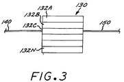
- FIG. 3 illustrates an exemplary semiconductor optical amplifier 130 connected to optical fibers 140 and 150.
- the amplifier 130 comprises a plurality of layers or regions 132A-N, with the fibers 140 and 150 coupled to the active layer (gain region) 132C.
- the use of semiconductor amplifiers in optical fiber links is described, for example, in "Optical Fiber Telecommunications II,” edited by S.E. Miller and I.P. Kaminow, Academic Press, Boston MA, 1988, at page 820 et seq.
Landscapes
- Engineering & Computer Science (AREA)
- Physics & Mathematics (AREA)
- Electromagnetism (AREA)
- Computer Networks & Wireless Communication (AREA)
- Signal Processing (AREA)
- Chemical & Material Sciences (AREA)
- Combustion & Propulsion (AREA)
- General Engineering & Computer Science (AREA)
- Lasers (AREA)
- Optical Communication System (AREA)
- Aiming, Guidance, Guns With A Light Source, Armor, Camouflage, And Targets (AREA)
- Light Guides In General And Applications Therefor (AREA)
Applications Claiming Priority (2)
| Application Number | Priority Date | Filing Date | Title |
|---|---|---|---|
| US93780292A | 1992-08-28 | 1992-08-28 | |
| US937802 | 1992-08-28 |
Publications (2)
| Publication Number | Publication Date |
|---|---|
| EP0585126A2 true EP0585126A2 (fr) | 1994-03-02 |
| EP0585126A3 EP0585126A3 (fr) | 1995-07-26 |
Family
ID=25470431
Family Applications (1)
| Application Number | Title | Priority Date | Filing Date |
|---|---|---|---|
| EP93306777A Withdrawn EP0585126A3 (fr) | 1992-08-28 | 1993-08-26 | Amplificateur bidirectionnel à fibre optique à grand rendement pour répétiteur de liaison de données pour le guidage des missiles. |
Country Status (4)
| Country | Link |
|---|---|
| US (1) | US5365368A (fr) |
| EP (1) | EP0585126A3 (fr) |
| JP (1) | JP2542164B2 (fr) |
| IL (1) | IL106766A (fr) |
Cited By (3)
| Publication number | Priority date | Publication date | Assignee | Title |
|---|---|---|---|---|
| GB2301249A (en) * | 1995-05-24 | 1996-11-27 | Bosch Gmbh Robert | Optical transceiver |
| EP0931370A4 (fr) * | 1996-10-10 | 2000-07-19 | Tyco Submarine Systems Ltd | Architecture d'un systeme de transmission optique sans perte |
| EP0914015A3 (fr) * | 1997-10-28 | 2003-03-12 | Nec Corporation | Commutateur optique, amplificateur optique et commande de puissance optique ainsi que multiplexeur optique a insertion-extraction |
Families Citing this family (17)
| Publication number | Priority date | Publication date | Assignee | Title |
|---|---|---|---|---|
| JP3269540B2 (ja) * | 1993-11-05 | 2002-03-25 | 富士ゼロックス株式会社 | 光増幅器 |
| US5563733A (en) * | 1994-08-25 | 1996-10-08 | Matsushita Electric Industrial Co., Ltd. | Optical fiber amplifier and optical fiber transmission system |
| JP2570639B2 (ja) * | 1994-12-02 | 1997-01-08 | 日本電気株式会社 | 光送信器 |
| IT1273465B (it) * | 1995-01-27 | 1997-07-08 | Pirelli Cavi Spa | Sistema di telecomunicazione ottica bidirezionale comprendente un amplificatore ottico bidirezionale |
| US5633741A (en) * | 1995-02-23 | 1997-05-27 | Lucent Technologies Inc. | Multichannel optical fiber communications |
| US5742416A (en) * | 1996-03-28 | 1998-04-21 | Ciena Corp. | Bidirectional WDM optical communication systems with bidirectional optical amplifiers |
| NL1002940C2 (nl) * | 1996-04-24 | 1997-10-28 | Nederland Ptt | Optisch netwerk met protectie-configuratie. |
| US6236496B1 (en) * | 1996-12-11 | 2001-05-22 | Nippon Telegraph And Telephone Corporation | Optical fiber amplifier and optical amplification method |
| US5889610A (en) * | 1996-12-31 | 1999-03-30 | Lucent Technologies Inc. | Optical protection switching system |
| US5959767A (en) * | 1996-12-31 | 1999-09-28 | Lucent Technologies | Loss-less optical cross-connect |
| US6563630B1 (en) * | 1997-09-29 | 2003-05-13 | Corning Incorporated | Optical amplifier apparatus |
| KR100259268B1 (ko) * | 1997-09-30 | 2000-06-15 | 강병호 | 일체화된 양방향 통신용 광증폭기의 광써큘레이터 및 파장분할기 |
| KR19990034429A (ko) * | 1997-10-29 | 1999-05-15 | 유기범 | 아이솔레이터를 이용한 양방향 광섬유증폭기 |
| KR100330411B1 (ko) * | 2000-02-07 | 2002-03-27 | 윤덕용 | 하나의 도파관열 격자 다중화기를 사용하는 파장교대방식양방향 애드/드롭 광증폭기 모듈 |
| JP2002135212A (ja) | 2000-10-20 | 2002-05-10 | Fujitsu Ltd | 双方向伝送可能な光波長分割多重伝送システム |
| US6686875B1 (en) | 2002-10-04 | 2004-02-03 | Phase Iv Systems, Inc. | Bi-directional amplifier module for insertion between microwave transmission channels |
| FR2856209B1 (fr) * | 2003-06-13 | 2005-08-05 | Thales Sa | Systeme de communication entre deux points d'emport d'un aeronef |
Family Cites Families (25)
| Publication number | Priority date | Publication date | Assignee | Title |
|---|---|---|---|---|
| US4551829A (en) * | 1982-03-10 | 1985-11-05 | Harris Corporation | Wavelength division multiplexed fiber-optic cable system with non-unique terminal types |
| US4709413A (en) * | 1982-09-10 | 1987-11-24 | American Telephone And Telegraph Company, At&T Bell Laboratories | Bidirectional fiber optic systems |
| US4674830A (en) * | 1983-11-25 | 1987-06-23 | The Board Of Trustees Of The Leland Stanford Junior University | Fiber optic amplifier |
| US4648083A (en) * | 1985-01-03 | 1987-03-03 | The United States Of America As Represented By The Secretary Of The Navy | All-optical towed and conformal arrays |
| US4700339A (en) * | 1986-01-28 | 1987-10-13 | American Telephone And Telegraph Company, At&T Bell Laboratories | Wavelength division multiplexed soliton optical fiber telecommunication system |
| GB8727846D0 (en) * | 1987-11-27 | 1987-12-31 | British Telecomm | Optical communications network |
| GB8709073D0 (en) * | 1987-04-15 | 1987-05-20 | British Telecomm | Coherent optical systems |
| DE3885389T2 (de) * | 1987-09-01 | 1994-03-24 | Nippon Electric Co | Optischer Zwischenverstärker. |
| US4901330A (en) * | 1988-07-20 | 1990-02-13 | Amoco Corporation | Optically pumped laser |
| US4867518A (en) * | 1988-08-31 | 1989-09-19 | The United States Of America As Represented By The Secretary Of The Navy | All-fiber SFPM amplifier |
| JPH02127829A (ja) * | 1988-11-08 | 1990-05-16 | Fujitsu Ltd | 双方向光伝送装置の光断検出回路 |
| FR2638854B1 (fr) * | 1988-11-10 | 1992-09-04 | Comp Generale Electricite | Amplificateur laser a fibre optique dopee |
| US5087108A (en) * | 1989-08-11 | 1992-02-11 | Societa' Cavi Pirelli S.P.A. | Double-core active-fiber optical amplifier having a wide-band signal wavelength |
| JP2677682B2 (ja) * | 1989-09-13 | 1997-11-17 | 日立電線株式会社 | 複数波長伝送用アクティブ伝送路及びそれを用いた伝送システム |
| US5005175A (en) * | 1989-11-27 | 1991-04-02 | At&T Bell Laboratories | Erbium-doped fiber amplifier |
| US5027079A (en) * | 1990-01-19 | 1991-06-25 | At&T Bell Laboratories | Erbium-doped fiber amplifier |
| US5005930A (en) * | 1990-02-23 | 1991-04-09 | Hughes Aircraft Company | Multi-directional payout fiber optic canister |
| US5012991A (en) * | 1990-03-15 | 1991-05-07 | The Boeing Company | Projectile with an obturator incorporating a motor |
| CA2042697C (fr) * | 1990-05-18 | 1994-08-16 | Kenji Tagawa | Amplificateur a fibres optiques |
| JPH0423628A (ja) * | 1990-05-18 | 1992-01-28 | Nec Corp | 光中継器 |
| DE4036327A1 (de) * | 1990-11-15 | 1992-05-21 | Standard Elektrik Lorenz Ag | Optisches nachrichtenuebertragungssystem mit einem faseroptischen verstaerker |
| JPH04217233A (ja) * | 1990-12-19 | 1992-08-07 | Nec Corp | 多波長光増幅装置 |
| CA2057264C (fr) * | 1991-02-15 | 1995-09-26 | Hai-Pin Hsu | Amplificateur pour liaison de communication a fibres optiques |
| DE69224340T2 (de) * | 1991-09-30 | 1998-06-04 | Nippon Electric Co | Zweiwegzwischenverstärker mit optischer Verstärkung |
| FR2687030A1 (fr) * | 1992-02-04 | 1993-08-06 | Alsthom Cge Alcatel | Installation de transmission bi-directionnelle d'informations par fibre(s) optique (s). |
-
1993
- 1993-08-23 IL IL10676693A patent/IL106766A/en active IP Right Review Request
- 1993-08-26 EP EP93306777A patent/EP0585126A3/fr not_active Withdrawn
- 1993-08-30 JP JP5214343A patent/JP2542164B2/ja not_active Expired - Lifetime
- 1993-12-29 US US08/174,929 patent/US5365368A/en not_active Expired - Lifetime
Cited By (5)
| Publication number | Priority date | Publication date | Assignee | Title |
|---|---|---|---|---|
| GB2301249A (en) * | 1995-05-24 | 1996-11-27 | Bosch Gmbh Robert | Optical transceiver |
| EP0931370A4 (fr) * | 1996-10-10 | 2000-07-19 | Tyco Submarine Systems Ltd | Architecture d'un systeme de transmission optique sans perte |
| EP1478060A1 (fr) * | 1996-10-10 | 2004-11-17 | Tyco Telecommunications (US) Inc. | Architecture d'un système de transmission optique sans perte |
| EP0914015A3 (fr) * | 1997-10-28 | 2003-03-12 | Nec Corporation | Commutateur optique, amplificateur optique et commande de puissance optique ainsi que multiplexeur optique a insertion-extraction |
| US7197246B2 (en) | 1997-10-28 | 2007-03-27 | Nec Corporation | Optical switch, optical amplifier and optical power controller as well as optical add-drop multiplexer |
Also Published As
| Publication number | Publication date |
|---|---|
| JP2542164B2 (ja) | 1996-10-09 |
| IL106766A (en) | 1995-12-31 |
| JPH06224506A (ja) | 1994-08-12 |
| US5365368A (en) | 1994-11-15 |
| IL106766A0 (en) | 1993-12-28 |
| EP0585126A3 (fr) | 1995-07-26 |
Similar Documents
| Publication | Publication Date | Title |
|---|---|---|
| US5365368A (en) | Efficient bi-directional optical fiber amplifier for missile guidance data link repeater | |
| US5742416A (en) | Bidirectional WDM optical communication systems with bidirectional optical amplifiers | |
| US5812306A (en) | Bidirectional WDM optical communication systems with bidirectional optical amplifiers | |
| US5532864A (en) | Optical monitoring channel for wavelength division multiplexed optical communication system | |
| EP0412727B1 (fr) | Système de communication optique | |
| EP0532230B1 (fr) | Amplificateurs optiques à pompage redondant | |
| AU699315B2 (en) | Amplified telecommunication system for wavelength-division multiplexing transmissions capable of limiting variations in the output power | |
| EP0555973A1 (fr) | Dispositif hybride de pompage pour amplificateurs à fibre dopée | |
| US5748363A (en) | Wavelength dependent crossover system for bi-directional transmission | |
| EP1199823A2 (fr) | Système de transmission optique bidirectionnel à multiplexage en longeur d'onde | |
| EP0499388B1 (fr) | Liaison de communication bidirective à fibre optique avec amplificateur | |
| EP3917036A2 (fr) | Égalisation du gain dans les amplificateurs à fibres dopées à l'erbium c+l | |
| US5673142A (en) | Optical amplifier with internal input signal monitoring tap | |
| US5801879A (en) | Device and method to supress Q-switching in an optical amplifying device | |
| JP4798997B2 (ja) | 単一のポンプ装置から異なる一対のファイバに位置する光ファイバへポンプ・エネルギを分配する方法および装置 | |
| US6934078B2 (en) | Dispersion-compensated erbium-doped fiber amplifier | |
| US6353497B1 (en) | Integrated modular optical amplifier | |
| US9825726B2 (en) | Efficient optical signal amplification systems and methods | |
| JP2677682B2 (ja) | 複数波長伝送用アクティブ伝送路及びそれを用いた伝送システム | |
| EP1113541A2 (fr) | Amplificateur optique utilisant l'amplification Raman | |
| JP3290707B2 (ja) | 光増幅器 | |
| JP2001028569A (ja) | ハイブリッドラマン増幅器 | |
| CN121984590A (en) | Optical communication system and optical communication architecture | |
| EP0878927B1 (fr) | Amélioration de la fiabilité d'un système de communication optique et d'une méthode approprée à cet effèt | |
| JPH03129330A (ja) | 光通信システム |
Legal Events
| Date | Code | Title | Description |
|---|---|---|---|
| PUAI | Public reference made under article 153(3) epc to a published international application that has entered the european phase |
Free format text: ORIGINAL CODE: 0009012 |
|
| AK | Designated contracting states |
Kind code of ref document: A2 Designated state(s): CH DE ES FR GB IT LI SE |
|
| PUAL | Search report despatched |
Free format text: ORIGINAL CODE: 0009013 |
|
| AK | Designated contracting states |
Kind code of ref document: A3 Designated state(s): CH DE ES FR GB IT LI SE |
|
| 17P | Request for examination filed |
Effective date: 19960105 |
|
| 17Q | First examination report despatched |
Effective date: 19960206 |
|
| STAA | Information on the status of an ep patent application or granted ep patent |
Free format text: STATUS: THE APPLICATION IS DEEMED TO BE WITHDRAWN |
|
| 18D | Application deemed to be withdrawn |
Effective date: 19960817 |