EP0585159A1 - Stickstoffgasgenerator aus einer Membran mit verbesserter Flexibilität - Google Patents
Stickstoffgasgenerator aus einer Membran mit verbesserter Flexibilität Download PDFInfo
- Publication number
- EP0585159A1 EP0585159A1 EP93402010A EP93402010A EP0585159A1 EP 0585159 A1 EP0585159 A1 EP 0585159A1 EP 93402010 A EP93402010 A EP 93402010A EP 93402010 A EP93402010 A EP 93402010A EP 0585159 A1 EP0585159 A1 EP 0585159A1
- Authority
- EP
- European Patent Office
- Prior art keywords
- membrane
- storage means
- demand
- product
- product storage
- Prior art date
- Legal status (The legal status is an assumption and is not a legal conclusion. Google has not performed a legal analysis and makes no representation as to the accuracy of the status listed.)
- Granted
Links
- IJGRMHOSHXDMSA-UHFFFAOYSA-N Atomic nitrogen Chemical compound N#N IJGRMHOSHXDMSA-UHFFFAOYSA-N 0.000 title claims abstract description 117
- 239000012528 membrane Substances 0.000 title claims abstract description 93
- 229910001873 dinitrogen Inorganic materials 0.000 title claims abstract description 18
- 239000000047 product Substances 0.000 claims abstract description 80
- 239000012530 fluid Substances 0.000 claims abstract description 21
- 238000001914 filtration Methods 0.000 claims abstract description 11
- 239000012466 permeate Substances 0.000 claims abstract description 9
- 229910052757 nitrogen Inorganic materials 0.000 claims description 50
- QVGXLLKOCUKJST-UHFFFAOYSA-N atomic oxygen Chemical compound [O] QVGXLLKOCUKJST-UHFFFAOYSA-N 0.000 claims description 36
- 239000001301 oxygen Substances 0.000 claims description 36
- 229910052760 oxygen Inorganic materials 0.000 claims description 36
- 239000007789 gas Substances 0.000 claims description 25
- 238000000034 method Methods 0.000 claims description 21
- 239000012510 hollow fiber Substances 0.000 claims description 17
- 239000000203 mixture Substances 0.000 claims description 7
- 238000004378 air conditioning Methods 0.000 claims description 3
- 239000000356 contaminant Substances 0.000 claims description 2
- 239000012263 liquid product Substances 0.000 claims description 2
- 238000011144 upstream manufacturing Methods 0.000 claims description 2
- 238000004519 manufacturing process Methods 0.000 description 21
- 239000000463 material Substances 0.000 description 11
- 238000000926 separation method Methods 0.000 description 9
- 239000004642 Polyimide Substances 0.000 description 7
- 229920001721 polyimide Polymers 0.000 description 7
- 230000008569 process Effects 0.000 description 6
- 239000004952 Polyamide Substances 0.000 description 5
- 229920002647 polyamide Polymers 0.000 description 5
- 125000003118 aryl group Chemical group 0.000 description 4
- 230000008901 benefit Effects 0.000 description 4
- -1 i.e. Substances 0.000 description 4
- 239000007788 liquid Substances 0.000 description 4
- 229920002492 poly(sulfone) Polymers 0.000 description 4
- 239000012467 final product Substances 0.000 description 3
- 239000004417 polycarbonate Substances 0.000 description 3
- 229920000515 polycarbonate Polymers 0.000 description 3
- CURLTUGMZLYLDI-UHFFFAOYSA-N Carbon dioxide Chemical compound O=C=O CURLTUGMZLYLDI-UHFFFAOYSA-N 0.000 description 2
- UFHFLCQGNIYNRP-UHFFFAOYSA-N Hydrogen Chemical compound [H][H] UFHFLCQGNIYNRP-UHFFFAOYSA-N 0.000 description 2
- 239000004793 Polystyrene Substances 0.000 description 2
- 230000000712 assembly Effects 0.000 description 2
- 238000000429 assembly Methods 0.000 description 2
- 229920002678 cellulose Polymers 0.000 description 2
- 239000001913 cellulose Substances 0.000 description 2
- 229920002301 cellulose acetate Polymers 0.000 description 2
- 229920006217 cellulose acetate butyrate Polymers 0.000 description 2
- 230000008859 change Effects 0.000 description 2
- 239000002131 composite material Substances 0.000 description 2
- 230000003247 decreasing effect Effects 0.000 description 2
- 238000010586 diagram Methods 0.000 description 2
- 239000001257 hydrogen Substances 0.000 description 2
- 229910052739 hydrogen Inorganic materials 0.000 description 2
- 238000012986 modification Methods 0.000 description 2
- 230000004048 modification Effects 0.000 description 2
- 229920006393 polyether sulfone Polymers 0.000 description 2
- 229920002223 polystyrene Polymers 0.000 description 2
- WSSSPWUEQFSQQG-UHFFFAOYSA-N 4-methyl-1-pentene Chemical compound CC(C)CC=C WSSSPWUEQFSQQG-UHFFFAOYSA-N 0.000 description 1
- BVKZGUZCCUSVTD-UHFFFAOYSA-L Carbonate Chemical compound [O-]C([O-])=O BVKZGUZCCUSVTD-UHFFFAOYSA-L 0.000 description 1
- 239000004696 Poly ether ether ketone Substances 0.000 description 1
- 239000004698 Polyethylene Substances 0.000 description 1
- 239000004743 Polypropylene Substances 0.000 description 1
- 229910002092 carbon dioxide Inorganic materials 0.000 description 1
- 239000001569 carbon dioxide Substances 0.000 description 1
- 229920003086 cellulose ether Polymers 0.000 description 1
- 238000005094 computer simulation Methods 0.000 description 1
- 239000000428 dust Substances 0.000 description 1
- 230000000694 effects Effects 0.000 description 1
- 150000002148 esters Chemical class 0.000 description 1
- 239000000835 fiber Substances 0.000 description 1
- 238000004868 gas analysis Methods 0.000 description 1
- 230000001771 impaired effect Effects 0.000 description 1
- 239000011261 inert gas Substances 0.000 description 1
- 230000007774 longterm Effects 0.000 description 1
- 238000012544 monitoring process Methods 0.000 description 1
- 150000002829 nitrogen Chemical class 0.000 description 1
- 229920001643 poly(ether ketone) Polymers 0.000 description 1
- 229920002530 polyetherether ketone Polymers 0.000 description 1
- 229920000573 polyethylene Polymers 0.000 description 1
- 229920000642 polymer Polymers 0.000 description 1
- 229920001155 polypropylene Polymers 0.000 description 1
- 229920001343 polytetrafluoroethylene Polymers 0.000 description 1
- 239000004810 polytetrafluoroethylene Substances 0.000 description 1
- 238000004886 process control Methods 0.000 description 1
- 238000000746 purification Methods 0.000 description 1
- 239000004627 regenerated cellulose Substances 0.000 description 1
- 239000013589 supplement Substances 0.000 description 1
- XLYOFNOQVPJJNP-UHFFFAOYSA-N water Chemical compound O XLYOFNOQVPJJNP-UHFFFAOYSA-N 0.000 description 1
Images

Classifications
-
- B—PERFORMING OPERATIONS; TRANSPORTING
- B01—PHYSICAL OR CHEMICAL PROCESSES OR APPARATUS IN GENERAL
- B01D—SEPARATION
- B01D53/00—Separation of gases or vapours; Recovering vapours of volatile solvents from gases; Chemical or biological purification of waste gases, e.g. engine exhaust gases, smoke, fumes, flue gases, aerosols
- B01D53/22—Separation of gases or vapours; Recovering vapours of volatile solvents from gases; Chemical or biological purification of waste gases, e.g. engine exhaust gases, smoke, fumes, flue gases, aerosols by diffusion
-
- B—PERFORMING OPERATIONS; TRANSPORTING
- B01—PHYSICAL OR CHEMICAL PROCESSES OR APPARATUS IN GENERAL
- B01D—SEPARATION
- B01D2317/00—Membrane module arrangements within a plant or an apparatus
- B01D2317/02—Elements in series
-
- B—PERFORMING OPERATIONS; TRANSPORTING
- B01—PHYSICAL OR CHEMICAL PROCESSES OR APPARATUS IN GENERAL
- B01D—SEPARATION
- B01D2317/00—Membrane module arrangements within a plant or an apparatus
- B01D2317/04—Elements in parallel
Definitions
- the present invention relates to a membrane nitrogen gas generator with improved flexibility, which is capable of providing an increased flow rate during periods of high demand.
- Membrane processes are used with increasing frequency in the production of inert gases from atmospheric air, wherein the oxygen content in the feed air stream through the membrane is decreased by permeation to a low pressure side.
- Membrane nitrogen generators are most frequently used in cases where customer applications can withstand a small amount of oxygen in the atmosphere, such as, for example, from 0.5 to 5% by volume oxygen.
- one method of overcoming this difficulty is to produce inert atmospheres at a pressure higher than is required by customer demand and storing excess production in a buffer tank during load demand periods for release in peak demand periods.
- Another method entails the use of bulk storage tanks to supplement generator production during peak demands.
- a membrane nitrogen gas generator containing feed stream compressing means, one or more membrane filtering means in fluid connection with the compressing means, and one or more product storage receiver means in fluid connection with and downstream of the one or more membrane filtering means, whereby excess production may be stored in periods of low demand at a purity level which is higher than required by customer need.
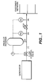
- FIG. 1 illustrates a generator and control means, including a product receiver, in accordance with the present invention.
- Figure 2 represents a series of time diagrams which illustrate the operation of the present invention, by monitoring several parameters as indicated as a function of variable customer demand.
- the present invention provides a membrane nitrogen gas generator, with improved flexibility containing at least one product storage receiver which is capable of storing excess production in periods of low demand at a purity level which is higher than that required by customer need.
- the present invention is predicated upon the discovery that by utilizing one or more gaseous or liquid product storage receivers containing such high-purity nitrogen product, for example, generation of product nitrogen may be boosted at periods of peak demand to produce nitrogen having an oxygen content deemed acceptable by the customer.
- the lower purity nitrogen produced by the generator is mixed with stored high-purity product, having an oxygen content under the maximum value deemed acceptable by the customer, whereby the final product meets customer specifications with respect to both quantity and quality.
- peak demand means a flow rate of about 120 to 1,000 units
- low demand means a flow rate of about 80 to 20 units or even less.
- high purity product or “improved purity product” means product the oxygen content of which is equal to nominal oxygen content, as requested by a customer, divided by a factor n, where n may have any value larger than 1, preferably between about 1.2 and 20.
- nitrogen with an oxygen content "over maximum value accepted by a customer” means product the oxygen content of which is equal to nominal oxygen content, as requested by the customer, multiplied by a factor m, where m may have any value larger than 1, preferably between about 1.2 and 3.
- one or more product storage receivers are used to store excess product, for example nitrogen, in periods of low demand at a purity level which is enhanced relative to customer need. Then, at periods of high or peak demand, generator production is boosted by increasing the oxygen content of the nitrogen, produced for example, over the maximum value acceptable by the customer. The low purity generator product is then mixed with stored product of high purity to afford a final product which meets customer specifications with respect to both quantity and quality.
- boosting generator production is intended to refer to a generator production having a value equal to about 1.1 to 5 times nominal production as a result of increasing the oxygen content in the product by a factor of about 2 to 8.
- the present invention also becomes increasingly advantageous as the capacity of the membrane nitrogen generator increases when the acceptable oxygen content increases also.
- the present invention is of particular advantage when using hollow fiber tube-fed membranes in a counter-current operating mode.
- Such membranes are known to those skilled in the art. Under such circumstances, for example, a surprising phenomenon is observed. Notably, the oxygen content increase due to production increase is much less than would be expected for shell-fed modules operated in a perfect counter-current mode. This phenomenon is particularly striking for large size industrial modules.
- a membrane system comprises a membrane module or a number of such modules, arranged for either parallel or series operation.
- the membrane modules can be constructed in convenient follow fiber form, or in spiral wound, pleated flat sheet membrane assemblies, or in any other desired configuration.
- Membrane modules are contracted to have a feed air surface side and an opposite permeate gas exit side.
- the feed air can be added either to the bore side or to the other surface side of the hollow fibers.
- the membrane material employed for the air separation membrane and for the hydrogen purification membrane can be any suitable material capable of selectively permeating a more readily permeable component of the feed gas, i.e., air or impure hydrogen.
- Cellulose derivatives such as cellulose acetate, cellulose acetate butyrate and the like, polyamides and polyimides, including aryl polyamides and aryl polyimides; polysulfones; polystyrenes and the like, are representative of such materials.
- polyimides are preferred.
- the permeable membranes comprising the membrane system positioned within the insulated enclosure of the invention may be in any desirable form, with hollow fiber membranes being generally preferred.
- the membrane material employed in any particular gas separation application can be any suitable material capable of selectively permeating a more readily permeable component of a gas or fluid mixture containing a less readily permeable component.
- Cellulose derivatives such as cellulose acetate, cellulose acetate butyrate, and the like; polyamides and polyimides, including aryl polyamides and aryl polyimides; polysulfones; polystyrenes and the like, are representative examples of such materials.
- membranes as employed in the practice of the invention, may be in composite membrane form, in asymmetric form or in any such form that is useful and effective for the particular gas separation being carried out using the system and process of the invention.
- the hollow fiber membranes are generally formed from a polymeric material which is capable of separating one or more fluids from one or more other fluids in a fluid mixture.
- the polymeric materials which may be used to prepare the hollow fiber membranes preferably include olefinic polymers, such as poly-4-methylpentene, polyethylene, and polypropylene; polytetrafluoroethylene; cellulosic esters, cellulose ethers, and regenerated cellulose; polyamides; polyetherketones and polyetheretherketones; polyestercarbonates and polycarbonates; polysulfones; polyimides; polyethersulfones; and the like.
- the hollow fiber membranes may be homogeneous, symmetric (isotropic), asymmetric (anisotropic), or composite membranes.
- the membranes may have a dense discriminating region which separates one or more fluids from one or more other fluids based on differences in solubility and diffusivity of the fluids in the dense region of the membrane.
- the membranes may be microporous and separate one or more fluids from one or more other fluids based on relative volatilities of the fluids.
- Hollow fiber membranes with dense regions are preferred for gas separations.
- Asymmetric hollow fiber membranes may have the discriminating region either on the outside of the hollow fiber, at the inside (lumen surface) of the hollow fiber, or located somewhere internal to both outside and inside hollow fiber membrane surfaces.
- the discriminating region of the hollow fiber membrane is internal to both hollow fiber membrane surfaces
- the inside (lumen) surface and the outside surface of the hollow fiber membrane are porous, yet the membrane demonstrates the ability to separate gases.
- the preferred polymeric materials for membranes include polyestercarbonates, polysulfones, polyethersulfones, polyimides, and the polycarbonates. More preferred polymeric materials for gas separation membranes include polycarbonates and polyestercarbonates.
- Preferred carbonate and polyestercarbonate membranes for gas separation include those described in U.S. Pat. Nos. 4,874,401, 4,851,014, 4,840,646, and 4,818,254; the relevant portions of each patent incorporated herein by reference for all legal purposes which may be served thereby.
- such membranes are prepared by the process described in U.S. Pat. No. 4,772,392, the relevant portions incorporated herein by reference for all legal purposes which may be served thereby.
- the above table includes data from industrial size module performance and shows that increased flow in an existing plant, assuming that sufficient air feed is available, has much less impact on product purity than would be expected based on computer simulation. This helps boost system production in case of customer consumption surge when advantage is taken of pure nitrogen stored while customer consumption is less than nominal generator production.
- the membrane nitrogen generator of the present invention contains compressing means, one or more membrane filtering means in fluid connection with and downstream of the compressing means, and one or more product storage receiver means in fluid connection with and downstream of the membrane filtering means, which is capable of storing product during periods of low demand having a superior purity, i.e., nitrogen having a reduced oxygen content, relative to customer need.
- the membranes used in accordance with the present invention may be any conventional membrane or membranes having permeate and non-permeate sides which is or are capable of separating nitrogen from atmospheric air or from mixtures of nitrogen and oxygen.
- the membrane or membranes be hollow fiber tube-fed membranes which are used in a counter-current mode.
- the present generator also includes air conditioning means downstream of the compressing means but upstream of the membrane for removal of oil, dust and other contaminants, such as carbon dioxide and water vapor.
- air conditioning means downstream of the compressing means but upstream of the membrane for removal of oil, dust and other contaminants, such as carbon dioxide and water vapor.
- conventional compressing means and air conditioning means may be used.
- one or more product receiver means may be used.
- multiple product receiver means such as two, three or four, may be advantageous in maintaining purity control.
- one product receiver means is sufficient.
- a tank or other reservoir or container means may be used.
- storage means for either gas or liquid may be used.
- Nominal Low Demand Peak demand Generator output (flow rate (nm3/h) 100 28 190 % oxygen in output 2 0.1% 4.85% product pressure bar 10 10.5 9.5
- Customer demand flow rate (Nm3/h) 100 10 490 % oxygen requested 2 2 2 product pressure required bar duration of peak demand (min.) 3 3 3
- Product receiver volume (Nm3) 20 product volume stored (Nm3) in low demand mode 150
- the generator is set in the normal or nominal mode through flow control valve and other control means, such as control means for air compressor flow and pressure, and membrane temperature, for example, to produce 100 Nm3/h product at 2% oxygen.
- flow in 3 equals flow in 1, with no net flow in 2.
- a product receiver is not used.
- PIC means a pressure (P) is available as an indicator or display (I) and is fed to a controller or computer (c).
- AIC means a gas analysis (A) is available on an indicator or display (I) and is fed to a controller or computer (c).
- PLC means a programmable logic controller, i.e. an industrial computer dedicated to process control functions.
- flow in 4 is low so that pressure in 3 will increase as a result of generator production.
- flow control means such as a valve, effects flow control so that production flow from the generator will decrease and the oxygen content in the product will decrease. Excess product will be stored in one or more product receivers until maximum present pressure level (PSH) is reached. Production will then either stop or adjust to customer demand.
- PSH maximum present pressure level
- flow in 4 is high so that pressure in 3 will decrease as a result of insufficient generator production.
- product stored previously in the receiver will be released to line 3 as a result of pressure lowering in 3.
- flow control means will adjust the control valve so that production from the generator will increase and oxygen content in product will increase up to a maximum value set by computer in such way that mixture of pure product from receiver and product from generator will give in 3 a total product with 02 content equal to customer requirement (2% in the example).
- Figure 2 represents time diagrams illustrating the relationship between several parameters, such as (using notation from Figure 1) flow in line 3, pressure in line 3, flow in line 1, flow in line 2 and % oxygen in line 1 versus variable customer demand.
- Figure 2a illustrates the relationship between customer demand (flow in line 3) as a function of nominal, low demand, peak demand and return to low demand.
- Figure 2b illustrates the relationship between customer demand (pressure in line 3) as a function of nominal, low demand, peak demand and return to low demand.
- Figure 2c illustrates the relationship between customer demand (flow in line 1) as a function of nominal, low demand, peak demand and return to low demand.
- Figure 2d illustrates the relationship between customer demand (flow in line 2) as a function of nominal, low demand, peak demand and return to low demand.
- Figure 2e illustrates the relationship between customer demand (% oxygen in line 1) as a function of nominal, low demand, peak demand and return to low demand.
- the present invention provides the surprising benefit of a 43% increase in the time where customer peak demand can be satisfied with given equipment.
- a typical membrane generator sized for production of 100 Nm3/h at 1% O2 is capable of producing 141 Nm3/h, i.e., 2.82 times nominal rate for 42 minutes if 100 Nm3 at 0.1% have previously been stored during low demand periods.
- a product of nominal purity may be stored in a receiver tank.
- the storage receiver in order to ensure the same flow and same product quantity, the storage receiver must be capable of storing 130 m3 at nominal purity.
- the present invention provides a method of generating a gas, such as nitrogen, for example, with improved flexibility, which generally entails first generating nitrogen from a membrane nitrogen generator, such that nitrogen having an enhanced purity relative to customer demand is produced during periods of low demand, and then storing this nitrogen in one or more product storage tanks or receivers. Thereafter, during periods of high demand, nitrogen is produced having a purity which is below that which meets customer demand, and which is then mixed with the stored nitrogen having a higher purity, thereby meeting customer requirements of quantity and quality.
- the present generator affords an increased flow rate during periods of high or peak demand.
- any type of membrane may be used which is conventionally used to generate the gas of interest, such as nitrogen gas.
- the pressures for the generator and product receiver may be generally in the range of about 1 to 50 bar, preferably in the range of about 6 to 14 bar.
- the product and receiver temperature are inconsequential, they may be generally in the range of about 0°C to about 100°C, preferably about 10°C to about 60°C.
- the present invention thus provides, in part, and in particular, a membrane nitrogen generator containing feed stream compressing means; one or more membrane filtering means each having a permeate side and a non-permeate side, in fluid connection with and downstream of the feed stream compressing means; and one or more product storage means for storing product nitrogen having a higher purity than is required by customer need, the product storage means being in fluid connection with and downstream of the membrane filtering means.
- the phrase "higher purity than is required by customer need” generally refers to a lower content of any component than is normally required by the customer, the component most often is oxygen. Thus, the higher purity will often refer to a lower oxygen content than is acceptable by the customer.
- the present invention also provides, in part, and in particular, a method of generating nitrogen with improved flexibility, which entails generating nitrogen from a membrane nitrogen generator, such that nitrogen having an enhanced purity relative to that which is acceptable by a customer is produced during periods of low generator demand; storing the nitrogen having enhanced purity in one or more product storage means; and mixing the stored nitrogen from the storage means with product having a lower purity than the stored nitrogen, the lower purity nitrogen being produced during periods of high generator demand, to produce a final mixture acceptable to customer specifications.
- the present invention also provides, in part, a method for increasing generator flow rate during a period of increased demand, which entails producing a lower purity gas than is required, and mixing therewith a stored gas having a higher purity than is required, to produce an increased flow rate of product, which is acceptable to customer specifications.
- the present invention also provides a method for increasing generator flow rate of nitrogen during a period of increased or peak demand, which entails generating nitrogen from a membrane nitrogen generator, whereby nitrogen having an enhanced purity relative to that which is deemed acceptable by a customer is produced during periods of low generator demand; storing the nitrogen having enhanced purity in one or more product storage means; and mixing the stored nitrogen from the storage means with product having a lower purity than the stored nitrogen, the lower purity nitrogen being produced during periods of high generator demand, to produce a final mixture acceptable to customer specifications.
- the present invention also provides an efficient means of customer load tracking.
- customer demand for quantity and quality of product gas will vary, for a nitrogen product, for example, customer demand will typically necessitate a final product oxygen content of no more than about 5% by volume of oxygen, preferably no more than about 2% by volume of oxygen therein.
- U.S. Patent 4,806,132 provides a method of turndown control which makes it possible to produce the exact quantity of nitrogen required without stopping the unit. This, however, makes a poor use of the separation capacity installed on-site and does not make any provision for meeting long peak demands.
- the present invention makes maximum use of installed separation capacity and, thus, provides a more efficient customer load tracking.
Landscapes
- Chemical & Material Sciences (AREA)
- Engineering & Computer Science (AREA)
- Analytical Chemistry (AREA)
- General Chemical & Material Sciences (AREA)
- Oil, Petroleum & Natural Gas (AREA)
- Chemical Kinetics & Catalysis (AREA)
- Separation Using Semi-Permeable Membranes (AREA)
Applications Claiming Priority (2)
| Application Number | Priority Date | Filing Date | Title |
|---|---|---|---|
| US935169 | 1992-08-26 | ||
| US07/935,169 US5302189A (en) | 1992-08-26 | 1992-08-26 | Membrane nitrogen gas generator with improved flexibility |
Publications (2)
| Publication Number | Publication Date |
|---|---|
| EP0585159A1 true EP0585159A1 (de) | 1994-03-02 |
| EP0585159B1 EP0585159B1 (de) | 2001-07-18 |
Family
ID=25466652
Family Applications (1)
| Application Number | Title | Priority Date | Filing Date |
|---|---|---|---|
| EP93402010A Expired - Lifetime EP0585159B1 (de) | 1992-08-26 | 1993-08-04 | Verfahren zur Herstellung von Stickstoff mit Hilfe einer Membrane |
Country Status (6)
| Country | Link |
|---|---|
| US (1) | US5302189A (de) |
| EP (1) | EP0585159B1 (de) |
| JP (1) | JPH06219712A (de) |
| CA (1) | CA2104811A1 (de) |
| DE (1) | DE69330449T2 (de) |
| ES (1) | ES2160590T3 (de) |
Cited By (2)
| Publication number | Priority date | Publication date | Assignee | Title |
|---|---|---|---|---|
| WO2017180422A1 (en) | 2016-04-15 | 2017-10-19 | Ac Distributing, Inc. | Nitrogen generator and uses thereof |
| US11897748B2 (en) | 2014-05-15 | 2024-02-13 | Automatic Bar Controls, Inc. | Chilled N2 infused beverage dispensing system to prepare and dispense a chilled N2 infused beverage |
Families Citing this family (16)
| Publication number | Priority date | Publication date | Assignee | Title |
|---|---|---|---|---|
| FR2707973B1 (fr) * | 1993-07-22 | 1995-09-08 | Air Liquide | Procédé de fourniture d'azote au moyen de membranes semi-perméables ou de séparateurs de gaz par adsorption. |
| FR2712821B1 (fr) * | 1993-11-26 | 1995-12-22 | Air Liquide | Procédé et installation de fourniture d'azote au moyen de membranes semi-perméables utilisant une géométrie membranaire variable. |
| US5425801A (en) * | 1993-12-21 | 1995-06-20 | Praxair Technology, Inc. | Membrane nitrogen with temperature tracking |
| US5496388A (en) * | 1994-07-01 | 1996-03-05 | Air Liquide America Corporation | System for compressing air and extracting nitrogen from compressed air |
| US5649995A (en) * | 1995-03-09 | 1997-07-22 | Nitec, Inc. | Nitrogen generation control systems and methods for controlling oxygen content in containers for perishable goods |
| US5681368A (en) * | 1995-07-05 | 1997-10-28 | Andrew Corporation | Dehumidifier system using membrane cartridge |
| US5688306A (en) * | 1995-07-18 | 1997-11-18 | Verini; Nicholas A. | Apparatus and method to intermittently manufacture and dispense nitrogen gas |
| US5855646A (en) * | 1995-07-18 | 1999-01-05 | Verini; Nicholas A. | Method and device to monitor nitrogen gas purity during the manufacture and dispensing of nitrogen gas |
| US5588984A (en) * | 1995-07-18 | 1996-12-31 | Verini; Nicholas A. | Apparatus and method to intermittently manufacture and dispense nitrogen |
| US5989312A (en) * | 1996-12-31 | 1999-11-23 | Praxair Technology, Inc. | Membrane control system and process |
| US6581694B2 (en) | 2000-12-29 | 2003-06-24 | Waukesha Electrical Systems, Inc. | Method and system for controlling the supply of nitrogen to electrical power handling equipment |
| US7081153B2 (en) * | 2003-12-02 | 2006-07-25 | Honeywell International Inc. | Gas generating system and method for inerting aircraft fuel tanks |
| US7387659B2 (en) | 2005-02-01 | 2008-06-17 | Parker Hannifin Corporation | Pneumatically operated automatic shutoff circuit for controlling the generation of gas |
| US20070012182A1 (en) * | 2005-07-18 | 2007-01-18 | Ingersoll-Rand Company | Fluid distribution system and method of operating the same |
| US8110027B2 (en) * | 2009-04-17 | 2012-02-07 | Hamilton Sundstrand Corporation | Heated blanket for air separation module |
| CN116550108A (zh) * | 2023-05-12 | 2023-08-08 | 上海科益生物科技有限公司 | 一种氮气发生装置 |
Citations (4)
| Publication number | Priority date | Publication date | Assignee | Title |
|---|---|---|---|---|
| EP0072630A1 (de) * | 1981-07-21 | 1983-02-23 | Osaka Gas Co., Ltd | Verbrennungsanlage |
| EP0409545A2 (de) * | 1989-07-19 | 1991-01-23 | The BOC Group plc | Trennung von Gasmischungen |
| US5129921A (en) * | 1991-05-30 | 1992-07-14 | Membrane Technology & Research, Inc. | Membrane gas separation process and apparatus |
| EP0517570A1 (de) * | 1991-06-03 | 1992-12-09 | L'air Liquide, Societe Anonyme Pour L'etude Et L'exploitation Des Procedes Georges Claude | Membraneinheit mit einer grossen Betriebsflexibilität |
Family Cites Families (17)
| Publication number | Priority date | Publication date | Assignee | Title |
|---|---|---|---|---|
| US3735558A (en) * | 1971-06-29 | 1973-05-29 | Perma Pure Process Inc | Process for separating fluids and apparatus |
| US4556180A (en) * | 1978-12-07 | 1985-12-03 | The Garrett Corporation | Fuel tank inerting system |
| US4818254A (en) * | 1986-04-14 | 1989-04-04 | The Dow Chemical Company | Semi-permeable membranes consisting predominantly of polycarbonates derived from tetrahalobisphenols |
| US4840646A (en) * | 1986-04-28 | 1989-06-20 | The Dow Chemical Company | Tetrabromo bisphenol based polyestercarbonate membranes and method of using |
| US4806132A (en) * | 1987-06-23 | 1989-02-21 | Union Carbide Corporation | Turndown control method for membrane separation systems |
| US4838904A (en) * | 1987-12-07 | 1989-06-13 | The Dow Chemical Company | Semi-permeable membranes with an internal discriminating region |
| US5030058A (en) * | 1987-11-09 | 1991-07-09 | Dorner Mfg. Corp. | Method for stacking articles and feeding the stacks to a discharge site |
| US4874401A (en) * | 1987-11-20 | 1989-10-17 | The Dow Chemical Company | Gas separation membranes from bisphenol AF polycarbonates and polyestercarbonates |
| US4851014A (en) * | 1988-07-01 | 1989-07-25 | The Dow Chemical Company | Gas separation membranes derived from polycarbonates, polyesters, and polyestercarbonates containing tetrafluorobisphenol F |
| US4857082A (en) * | 1988-09-15 | 1989-08-15 | Air Products And Chemicals, Inc. | Membrane unit turn-down control system |
| US4931070A (en) * | 1989-05-12 | 1990-06-05 | Union Carbide Corporation | Process and system for the production of dry, high purity nitrogen |
| US4944776A (en) * | 1989-10-05 | 1990-07-31 | Andrew Corporation | Dehumidifier for waveguide system |
| US5118327A (en) * | 1989-10-05 | 1992-06-02 | Andrew Corporation | Dehumidifier for supplying gas having controlled dew point |
| US5030251A (en) * | 1989-10-30 | 1991-07-09 | Permea, Inc. | System and method for separating a portion of a gas from a mixture of gases |
| GB9001226D0 (en) * | 1990-01-19 | 1990-03-21 | Boc Group Plc | Gas seperation apparatus |
| US5102432A (en) * | 1990-12-10 | 1992-04-07 | Union Carbide Industrial Gases Technology Corporation | Three-stage membrane gas separation process and system |
| US5131929A (en) * | 1991-05-06 | 1992-07-21 | Permea, Inc. | Pressure control for improved gas dehydration in systems which employ membrane dryers in intermittent service |
-
1992
- 1992-08-26 US US07/935,169 patent/US5302189A/en not_active Expired - Fee Related
-
1993
- 1993-08-04 EP EP93402010A patent/EP0585159B1/de not_active Expired - Lifetime
- 1993-08-04 DE DE69330449T patent/DE69330449T2/de not_active Expired - Fee Related
- 1993-08-04 ES ES93402010T patent/ES2160590T3/es not_active Expired - Lifetime
- 1993-08-24 JP JP5209743A patent/JPH06219712A/ja not_active Ceased
- 1993-08-25 CA CA002104811A patent/CA2104811A1/en not_active Abandoned
Patent Citations (4)
| Publication number | Priority date | Publication date | Assignee | Title |
|---|---|---|---|---|
| EP0072630A1 (de) * | 1981-07-21 | 1983-02-23 | Osaka Gas Co., Ltd | Verbrennungsanlage |
| EP0409545A2 (de) * | 1989-07-19 | 1991-01-23 | The BOC Group plc | Trennung von Gasmischungen |
| US5129921A (en) * | 1991-05-30 | 1992-07-14 | Membrane Technology & Research, Inc. | Membrane gas separation process and apparatus |
| EP0517570A1 (de) * | 1991-06-03 | 1992-12-09 | L'air Liquide, Societe Anonyme Pour L'etude Et L'exploitation Des Procedes Georges Claude | Membraneinheit mit einer grossen Betriebsflexibilität |
Cited By (6)
| Publication number | Priority date | Publication date | Assignee | Title |
|---|---|---|---|---|
| US11897748B2 (en) | 2014-05-15 | 2024-02-13 | Automatic Bar Controls, Inc. | Chilled N2 infused beverage dispensing system to prepare and dispense a chilled N2 infused beverage |
| WO2017180422A1 (en) | 2016-04-15 | 2017-10-19 | Ac Distributing, Inc. | Nitrogen generator and uses thereof |
| EP3442692A4 (de) * | 2016-04-15 | 2019-12-11 | Automatic Bar Controls, Inc. | Stickstoffgenerator und verwendungen davon |
| US10752484B2 (en) | 2016-04-15 | 2020-08-25 | Automatic Bar Controls, Inc. | Nitrogen generator and uses thereof |
| US11066287B2 (en) | 2016-04-15 | 2021-07-20 | Automatic Bar Controls, Inc. | Nitrogen generator and uses thereof |
| AU2017249108B2 (en) * | 2016-04-15 | 2022-08-25 | Automatic Bar Controls, Inc. | Nitrogen generator and uses thereof |
Also Published As
| Publication number | Publication date |
|---|---|
| JPH06219712A (ja) | 1994-08-09 |
| US5302189A (en) | 1994-04-12 |
| DE69330449T2 (de) | 2002-05-02 |
| EP0585159B1 (de) | 2001-07-18 |
| CA2104811A1 (en) | 1994-02-27 |
| ES2160590T3 (es) | 2001-11-16 |
| DE69330449D1 (de) | 2001-08-23 |
Similar Documents
| Publication | Publication Date | Title |
|---|---|---|
| US5302189A (en) | Membrane nitrogen gas generator with improved flexibility | |
| US5266101A (en) | Membrane gas generator in association with bulk storage for increased flexibility and productivity | |
| EP1255605B1 (de) | Verfahren zur herstellung stickstoffangereicherter luft | |
| US4781907A (en) | Production of membrane-derived nitrogen from combustion gases | |
| US5281253A (en) | Multistage membrane control system and process | |
| US4119417A (en) | Gas separator | |
| US4140499A (en) | Gas mixture-separating device | |
| EP0603798A1 (de) | Membranverfahren für die Herstellung von hochreinem Stickstoff | |
| US3246449A (en) | Recovery of helium | |
| EP3446771B1 (de) | Membranbasierte gastrennung mit retentatspülung | |
| EP0555878A1 (de) | Zweistufiger Membrantrockner | |
| EP0359149A1 (de) | Regeleinrichtung zur Drosselung einer Membraneinheit | |
| US5314528A (en) | Permeation process and apparatus | |
| CA2104808C (en) | Fast response high purity membrane nitrogen generator | |
| EP0430304B1 (de) | Trennung von Gasgemischen | |
| KR930009641A (ko) | 막 산소 공정 및 시스템 | |
| US5306427A (en) | Low pressure feed membrane separation process | |
| US5015269A (en) | Gas separation | |
| US5129921A (en) | Membrane gas separation process and apparatus | |
| EP0551158A1 (de) | Verfahren und Einrichtung zum Konditionieren der Atmosphäre für Speicherkammer von organischen Ernteprodukten | |
| US4957513A (en) | Method of purifying a mixed H2 /H2 Se vapor stream | |
| EP0695574B1 (de) | Gastrennung mit Spülgas zur Vor- oder Nachreinigung | |
| Röhr et al. | A comparison of two commercial membranes used for biogas upgrading | |
| US5411581A (en) | Gas separation apparatus | |
| Fabiani et al. | Performance of a hollow fibre membrane unit in oxygen-enriched air production |
Legal Events
| Date | Code | Title | Description |
|---|---|---|---|
| PUAI | Public reference made under article 153(3) epc to a published international application that has entered the european phase |
Free format text: ORIGINAL CODE: 0009012 |
|
| 17P | Request for examination filed |
Effective date: 19930809 |
|
| AK | Designated contracting states |
Kind code of ref document: A1 Designated state(s): BE DE ES FR IT NL SE |
|
| 17Q | First examination report despatched |
Effective date: 19950614 |
|
| RAP1 | Party data changed (applicant data changed or rights of an application transferred) |
Owner name: L'AIR LIQUIDE, SOCIETE ANONYME POUR L'ETUDE ET L'E |
|
| RTI1 | Title (correction) |
Free format text: A METHOD OF OBTAINING NITROGEN GAS USING A MEMBRANE GENERATOR |
|
| GRAG | Despatch of communication of intention to grant |
Free format text: ORIGINAL CODE: EPIDOS AGRA |
|
| RTI1 | Title (correction) |
Free format text: A METHOD OF OBTAINING NITROGEN GAS USING A MEMBRANE GENERATOR |
|
| GRAG | Despatch of communication of intention to grant |
Free format text: ORIGINAL CODE: EPIDOS AGRA |
|
| GRAH | Despatch of communication of intention to grant a patent |
Free format text: ORIGINAL CODE: EPIDOS IGRA |
|
| GRAH | Despatch of communication of intention to grant a patent |
Free format text: ORIGINAL CODE: EPIDOS IGRA |
|
| GRAA | (expected) grant |
Free format text: ORIGINAL CODE: 0009210 |
|
| AK | Designated contracting states |
Kind code of ref document: B1 Designated state(s): BE DE ES FR IT NL SE |
|
| PG25 | Lapsed in a contracting state [announced via postgrant information from national office to epo] |
Ref country code: NL Free format text: LAPSE BECAUSE OF FAILURE TO SUBMIT A TRANSLATION OF THE DESCRIPTION OR TO PAY THE FEE WITHIN THE PRESCRIBED TIME-LIMIT Effective date: 20010718 Ref country code: BE Free format text: LAPSE BECAUSE OF FAILURE TO SUBMIT A TRANSLATION OF THE DESCRIPTION OR TO PAY THE FEE WITHIN THE PRESCRIBED TIME-LIMIT Effective date: 20010718 |
|
| REF | Corresponds to: |
Ref document number: 69330449 Country of ref document: DE Date of ref document: 20010823 |
|
| ITF | It: translation for a ep patent filed | ||
| ET | Fr: translation filed | ||
| PG25 | Lapsed in a contracting state [announced via postgrant information from national office to epo] |
Ref country code: SE Free format text: LAPSE BECAUSE OF FAILURE TO SUBMIT A TRANSLATION OF THE DESCRIPTION OR TO PAY THE FEE WITHIN THE PRESCRIBED TIME-LIMIT Effective date: 20011018 |
|
| REG | Reference to a national code |
Ref country code: ES Ref legal event code: FG2A Ref document number: 2160590 Country of ref document: ES Kind code of ref document: T3 |
|
| NLV1 | Nl: lapsed or annulled due to failure to fulfill the requirements of art. 29p and 29m of the patents act | ||
| RAP2 | Party data changed (patent owner data changed or rights of a patent transferred) |
Owner name: L'AIR LIQUIDE, S.A. A DIRECTOIRE ET CONSEIL DE SUR |
|
| PLBE | No opposition filed within time limit |
Free format text: ORIGINAL CODE: 0009261 |
|
| STAA | Information on the status of an ep patent application or granted ep patent |
Free format text: STATUS: NO OPPOSITION FILED WITHIN TIME LIMIT |
|
| 26N | No opposition filed | ||
| PGFP | Annual fee paid to national office [announced via postgrant information from national office to epo] |
Ref country code: FR Payment date: 20040708 Year of fee payment: 12 |
|
| PGFP | Annual fee paid to national office [announced via postgrant information from national office to epo] |
Ref country code: DE Payment date: 20040716 Year of fee payment: 12 |
|
| PGFP | Annual fee paid to national office [announced via postgrant information from national office to epo] |
Ref country code: ES Payment date: 20040804 Year of fee payment: 12 |
|
| PG25 | Lapsed in a contracting state [announced via postgrant information from national office to epo] |
Ref country code: IT Free format text: LAPSE BECAUSE OF NON-PAYMENT OF DUE FEES;WARNING: LAPSES OF ITALIAN PATENTS WITH EFFECTIVE DATE BEFORE 2007 MAY HAVE OCCURRED AT ANY TIME BEFORE 2007. THE CORRECT EFFECTIVE DATE MAY BE DIFFERENT FROM THE ONE RECORDED. Effective date: 20050804 |
|
| PG25 | Lapsed in a contracting state [announced via postgrant information from national office to epo] |
Ref country code: ES Free format text: LAPSE BECAUSE OF NON-PAYMENT OF DUE FEES Effective date: 20050805 |
|
| PG25 | Lapsed in a contracting state [announced via postgrant information from national office to epo] |
Ref country code: DE Free format text: LAPSE BECAUSE OF NON-PAYMENT OF DUE FEES Effective date: 20060301 |
|
| PG25 | Lapsed in a contracting state [announced via postgrant information from national office to epo] |
Ref country code: FR Free format text: LAPSE BECAUSE OF NON-PAYMENT OF DUE FEES Effective date: 20060428 |
|
| REG | Reference to a national code |
Ref country code: FR Ref legal event code: ST Effective date: 20060428 |
|
| REG | Reference to a national code |
Ref country code: ES Ref legal event code: FD2A Effective date: 20050805 |