EP0585194A1 - Misch- und Strömungverteiler - Google Patents
Misch- und Strömungverteiler Download PDFInfo
- Publication number
- EP0585194A1 EP0585194A1 EP93630053A EP93630053A EP0585194A1 EP 0585194 A1 EP0585194 A1 EP 0585194A1 EP 93630053 A EP93630053 A EP 93630053A EP 93630053 A EP93630053 A EP 93630053A EP 0585194 A1 EP0585194 A1 EP 0585194A1
- Authority
- EP
- European Patent Office
- Prior art keywords
- ejector
- passage
- air flow
- flow
- air
- Prior art date
- Legal status (The legal status is an assumption and is not a legal conclusion. Google has not performed a legal analysis and makes no representation as to the accuracy of the status listed.)
- Granted
Links
- 230000003134 recirculating effect Effects 0.000 claims description 12
- 238000011144 upstream manufacturing Methods 0.000 claims description 11
- 230000000149 penetrating effect Effects 0.000 claims 1
- 230000001737 promoting effect Effects 0.000 claims 1
- 230000007480 spreading Effects 0.000 abstract description 13
- 238000010586 diagram Methods 0.000 description 4
- 230000007547 defect Effects 0.000 description 2
- 230000006872 improvement Effects 0.000 description 2
- 230000003993 interaction Effects 0.000 description 2
- 230000000694 effects Effects 0.000 description 1
- 230000009467 reduction Effects 0.000 description 1
- 238000009423 ventilation Methods 0.000 description 1
Images




Classifications
-
- F—MECHANICAL ENGINEERING; LIGHTING; HEATING; WEAPONS; BLASTING
- F24—HEATING; RANGES; VENTILATING
- F24F—AIR-CONDITIONING; AIR-HUMIDIFICATION; VENTILATION; USE OF AIR CURRENTS FOR SCREENING
- F24F13/00—Details common to, or for air-conditioning, air-humidification, ventilation or use of air currents for screening
- F24F13/26—Arrangements for air-circulation by means of induction, e.g. by fluid coupling or thermal effect
Definitions
- This invention relates generally to air handling systems. More particularly the invention relates to devices that improve the flow characteristics of air in ducts and across heat exchangers.
- the jet spreading angle from a simple exhaust port such as the end of a circular ventilation pipe tends to be on the order of 5 to 8 degrees half angle. This is shown schematically in FIG. 1 where air exiting the end of duct 10 spreads to half angle ⁇ as it enters the space downstream of the duct.
- the spreading half angle is a function of the eddy structure of the free shear layer turbulence at the exhaust port.
- FIG. 2A shows schematically bluff body 02 installed in air flow duct 01'.
- FIG. 2B shows schematically bluff body 02 installed in air flow duct 01'.
- the present invention is a mixer ejector flow distributor to increase the uniformity of the flow exiting an exhaust port in an air duct by increasing the spreading angle of the jet exiting the port or to increase the uniformity of flow immediately downstream of a bluff body in the duct.
- Increasing the jet spreading angle is an improvement in many applications. Improvement in flow uniformity results in reduced noise, lower duct pressure losses and can improve the performance of a heat exchanger located downstream of the exhaust port or bluff body.
- the flow distributor comprises a wall installed in conjunction with a faired body having an airfoil cross section to form an ejector passage between one side of the wall and the faired body. There is a primary flow passage on the other side of the wall.
- the wall has a plurality of convoluted corrugations or lobes that extend into both the primary flow and ejector flow passages so that a lobe in one passage is a trough in the other passage.
- Air flow in the primary flow passage acts to cause a flow through the ejector passage and thus a suction at the inlet to the ejector passage.
- the flow distributor is installed at the outlet of the exhaust port, with the faired body surrounding the convoluted wall.
- An outlet cuff closed at its upstream, with respect to primary air flow direction, end, surrounds the faired body to form a recirculating air passage between the cuff and the faired body.
- the recirculating air passage has a recirculating air inlet formed between the trailing edge of the faired body and the downstream end of the outlet cuff.
- the suction at the inlet to the ejector passage causes a flow of air in the recirculating air passage and a suction at the recirculating air inlet. This suction turns the streamlines of the air jet exiting the flow distributor and results in a spreading angle that is much larger than is present in the exhaust from a duct without a flow distributor.
- the flow distributor is installed at and immediately downstream of the bluff body.
- the faired body is mounted inside the convoluted wall.
- the suction at the ejector passage inlet causes a strong inward deflection of the streamlines from the bluff body, minimizing wake defect and producing an associated increase in base pressure and reduced drag as well as a more uniform air flow velocity profile downstream of the bluff body.
- FIGS. 3 , 4A and 4B depict one embodiment of the present invention.
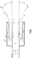
- FIG. 5 depicts schematically the air flow in the embodiment.
- a mixer ejector flow distributor is installed at the outlet of an air duct in order to increase the amount of spreading of the air flow exiting the duct.
- This embodiment of the invention would be employed, for example, at the outlet of a duct into a plenum containing a heat exchanger in order to increase the uniformity of air flow over the face of the heat exchanger.
- mixer ejector flow distributor 20 is fitted around the outlet of duct 11.
- Flow distributor 20 comprises wall means 21, faired body 22 and outlet cuff 23 .
- Faired body 22 has a cross section, in a plane that passes through axis of symmetry A of both duct 11 and flow distributor 20, that is generally an airfoil, that airfoil having leading edge 41 and trailing edge 42.
- Faired body 22 is outside, with respect to axis A, of wall means 21.
- Ejector passage 51 from extending ejector inlet 52 to ejector outlet 53 , is formed between wall means 21 and faired body 22.
- Upstream end 61 of cuff 22 is closed around duct 11 while downstream end 62 of the cuff is open.
- Recirculating air inlet 64 is formed between cuff downstream end 62 and trailing edge 42 of faired body 22.
- Recirculating air passage 63 extending from recirculating air inlet 64 to ejector inlet 52, is formed between faired body 22 and outlet cuff 23.
- the interior of duct 11 forms primary flow passage 71.
- Wall means 21 separates primary flow passage 71 from ejector flow passage 51.
- wall means 21 are a plurality of circumferentially spaced lobes 31 aligned longitudinally to the direction of air flow in primary flow passage 71 and extending entirely around the periphery of duct 11.
- Lobes 31 penetrate alternately into both primary flow passage 71 and ejector flow passage 51 so that a lobe in one of the passages is a trough in the other.
- the height of lobes 31 increases gradually in a upstream to downstream direction.
- Lobes 31 have lobe end 32 that, when viewed from downstream (FIG. 4B), presents a wave-like appearance.
- FIG. 5 shows mixer ejector flow distributor 20 in operation.
- a primary flow of air passes through the lobes of wall means 21.
- Mixing interaction between the primary air flow and air from ejector passage 51 causes a flow of air in ejector passage 51.
- This in turn causes a flow of air in recirculating air passage 63 and a suction at recirculating air inlet 54.
- This suction turns the streamlines of the air jet exiting flow distributor 20 outward and results in a spreading half angle ⁇ that is much larger than the half angle that would exist in the exhaust from a duct without a flow distributor ( Cf . angle ⁇ in FIG. 1 ).
- FIGS. 6, 7A and 7B depict another embodiment of the present invention.
- FIGS. 8A and 8B depict, respectively, schematically the air flow in the embodiment and the velocity profile across the duct in which the invention is installed.
- a mixer ejector flow distributor is installed at and downstream of a bluff body in an air duct.
- the flow distributor functions to reduce the variation of air flow velocities across the duct at a point downstream of the body.
- This embodiment of the invention would be employed, for example, downstream of a fan motor or other bluff body in a duct to reduce bluff body drag and velocity gradients and, as well, to reduce pressure losses in the duct due to the presence of the bluff body.
- mixer ejector flow distributor 20' is fitted at the downstream end of bluff body 12, which body is located in duct 11' .
- Flow distributor 20' comprises wall means 21' and faired body 22' .
- Faired body 22' has a cross section, in a plane that passes through axis of symmetry A' of both duct 11' and flow distributor 20' , that is generally an airfoil, that airfoil having leading edge 41' and trailing edge 42'.
- Faired body 22' is inside, with respect to axis A', of wall means 21' .
- Ejector passage 51' from ejector inlet 52' to ejector outlet 53' , is formed between wall means 21' and faired body 22' .
- the interior of duct 11' around bluff body 12 forms primary flow passage 71' .
- Wall means 21' separates primary flow passage 71' from ejector flow passage 51' .
- wall means 21' are a plurality of circumferentially spaced lobes 31' aligned longitudinally to the direction of air flow in primary flow passage 71' and extending entirely around the periphery of bluff body 12.
- Lobes 31' penetrate alternately into both primary flow passage 71' and ejector flow passage 51' so that a lobe in one of the passages is a trough in the other.
- the height of lobes 31' increases gradually in a upstream to downstream direction.
- Lobes 31' have lobe end 32' that, when viewed from downstream (FIG. 7B) , presents a wave-like appearance.
- FIG. 8A shows mixer ejector flow distributor 20' in operation.
- a primary flow of air passes through the lobes of wall means 21'.
- Mixing interaction between the primary air flow and air from ejector passage 51' causes a flow of air in ejector passage 51' and a resulting suction at ejector inlet 52' .
- This suction in turn causes a strong inward deflection of the bluff body wake streamlines, minimizing wake defect and producing an associated increase in base pressure, hence reducing drag from the bluff body.
- this effect results in a more uniform air flow velocity profile across duct 11' downstream of bluff body 12 ( Cf . the profile shown in FIG. 2B ).
- FIGS. 3 , 4B, 6 and 7B show ducting and flow distributors that are circular in lateral cross section.
- the present invention envisions that applications of its flow distributor in ducting of other lateral cross sectional configurations, such as square, rectangular or oval, are equally feasible.
Landscapes
- Engineering & Computer Science (AREA)
- Chemical & Material Sciences (AREA)
- Combustion & Propulsion (AREA)
- Mechanical Engineering (AREA)
- General Engineering & Computer Science (AREA)
- Jet Pumps And Other Pumps (AREA)
- Duct Arrangements (AREA)
- Air-Flow Control Members (AREA)
Applications Claiming Priority (2)
| Application Number | Priority Date | Filing Date | Title |
|---|---|---|---|
| US925000 | 1992-08-05 | ||
| US07/925,000 US5230656A (en) | 1992-08-05 | 1992-08-05 | Mixer ejector flow distributor |
Publications (2)
| Publication Number | Publication Date |
|---|---|
| EP0585194A1 true EP0585194A1 (de) | 1994-03-02 |
| EP0585194B1 EP0585194B1 (de) | 1996-09-18 |
Family
ID=25451057
Family Applications (1)
| Application Number | Title | Priority Date | Filing Date |
|---|---|---|---|
| EP93630053A Expired - Lifetime EP0585194B1 (de) | 1992-08-05 | 1993-08-05 | Misch- und Strömungverteiler |
Country Status (4)
| Country | Link |
|---|---|
| US (1) | US5230656A (de) |
| EP (1) | EP0585194B1 (de) |
| JP (1) | JPH06159789A (de) |
| DE (1) | DE69304848T2 (de) |
Cited By (3)
| Publication number | Priority date | Publication date | Assignee | Title |
|---|---|---|---|---|
| DE19542521A1 (de) * | 1995-11-15 | 1997-05-22 | Ruhrgas Ag | Verfahren und Brenner zum Verbrennen eines Luft/Brennstoff-Gemisches |
| EP0855521A3 (de) * | 1996-11-12 | 1999-03-24 | Hoval Interliz Ag | Verfahren und Vorrichtung zum freien Transportieren eines Fluids |
| US9291177B2 (en) | 2010-06-01 | 2016-03-22 | Esg Mbh | Duct having flow conducting surfaces |
Families Citing this family (39)
| Publication number | Priority date | Publication date | Assignee | Title |
|---|---|---|---|---|
| AUPN164695A0 (en) * | 1995-03-10 | 1995-04-06 | Luminis Pty Limited | Improved induction nozzle and arrangement |
| DE102004007145B4 (de) * | 2004-02-12 | 2009-09-24 | Noorkami Jamshid | Strömungsleitelement und eine damit ausgestattete strömungstechnische Anlage |
| AU2007321712A1 (en) * | 2006-11-16 | 2008-05-22 | Holyoake Industries (Vic) Pty Ltd | Plenum chamber |
| US20100314885A1 (en) * | 2007-03-23 | 2010-12-16 | Flodesign Wind Turbine Corporation | Shrouded wind turbine with rim generator and halbach array |
| US8622688B2 (en) * | 2007-03-23 | 2014-01-07 | Flodesign Wind Turbine Corp. | Fluid turbine |
| US20110027067A1 (en) * | 2007-03-23 | 2011-02-03 | Flodesign Wind Turbine Corporation | Coated shrouded wind turbine |
| US8393850B2 (en) * | 2008-09-08 | 2013-03-12 | Flodesign Wind Turbine Corp. | Inflatable wind turbine |
| US20100028132A2 (en) * | 2007-03-23 | 2010-02-04 | Flodesign Wind Turbine Corporation | Wind turbine with mixers and ejectors |
| US20100316493A1 (en) * | 2007-03-23 | 2010-12-16 | Flodesign Wind Turbine Corporation | Turbine with mixers and ejectors |
| US20110020107A1 (en) * | 2007-03-23 | 2011-01-27 | Flodesign Wind Turbine Corporation | Molded wind turbine shroud segments and constructions for shrouds |
| US8376686B2 (en) * | 2007-03-23 | 2013-02-19 | Flodesign Wind Turbine Corp. | Water turbines with mixers and ejectors |
| US8714923B2 (en) * | 2007-03-23 | 2014-05-06 | Ogin, Inc. | Fluid turbine |
| US8021100B2 (en) * | 2007-03-23 | 2011-09-20 | Flodesign Wind Turbine Corporation | Wind turbine with mixers and ejectors |
| US20110014038A1 (en) * | 2007-03-23 | 2011-01-20 | Flodesign Wind Turbine Corporation | Wind turbine with skeleton-and-skin structure |
| US20090230691A1 (en) * | 2007-03-23 | 2009-09-17 | Presz Jr Walter M | Wind turbine with mixers and ejectors |
| US8657572B2 (en) | 2007-03-23 | 2014-02-25 | Flodesign Wind Turbine Corp. | Nacelle configurations for a shrouded wind turbine |
| US7696634B2 (en) * | 2007-05-01 | 2010-04-13 | Pliant Energy Systems Llc | Pliant mechanisms for extracting power from moving fluid |
| US8432057B2 (en) * | 2007-05-01 | 2013-04-30 | Pliant Energy Systems Llc | Pliant or compliant elements for harnessing the forces of moving fluid to transport fluid or generate electricity |
| US8696192B2 (en) * | 2007-05-10 | 2014-04-15 | Fluid-Quip, Inc. | Multiple helical vortex baffle |
| KR101479369B1 (ko) * | 2007-09-21 | 2015-01-05 | 에어그린 엘티디. | 공조 시스템들로부터 공기 제트를 방출하고 주위 공기를 혼합시키는 장치 |
| US7823510B1 (en) | 2008-05-14 | 2010-11-02 | Pratt & Whitney Rocketdyne, Inc. | Extended range projectile |
| US7891298B2 (en) | 2008-05-14 | 2011-02-22 | Pratt & Whitney Rocketdyne, Inc. | Guided projectile |
| CA2755135A1 (en) * | 2009-03-30 | 2010-10-07 | Flodesign Wind Turbine Corporation | Segmented wind turbine |
| GB0908355D0 (en) * | 2009-05-15 | 2009-06-24 | Bailey Ralph Peter S | Wind turbine diffuser |
| EP2662558A3 (de) | 2011-01-10 | 2015-01-14 | Benjamin Filardo | Mechanismus zum Erzeugen wellenförmiger Bewegungen wie zum Antrieb und zur Nutzung der Energie eines strömenden Mediums |
| EP2718644B1 (de) | 2011-06-10 | 2020-09-09 | Carrier Corporation | Ausstosser mit beweglichem strömungswirbler |
| NO2691706T3 (de) | 2011-06-27 | 2018-05-12 | ||
| DE102011118735A1 (de) * | 2011-11-17 | 2013-05-23 | Alstom Technology Ltd. | Diffusor, insbesondere für eine axiale strömungsmaschine |
| US9527594B2 (en) * | 2012-04-24 | 2016-12-27 | Hamilton Sundstrand Corporation | Condenser with recirculation air mixer |
| JP6020352B2 (ja) * | 2013-05-28 | 2016-11-02 | 豊田合成株式会社 | ダクト装置 |
| FR3020132B1 (fr) * | 2014-04-17 | 2016-05-27 | Cie Ind D'applications Thermiques | Dispositif de diffusion avec inserts lobes et ventilo-convecteur comprenant un tel dispositif |
| US11209022B2 (en) | 2016-06-30 | 2021-12-28 | Pliant Energy Systems Llc | Vehicle with traveling wave thrust module apparatuses, methods and systems |
| US11795900B2 (en) | 2016-06-30 | 2023-10-24 | Pliant Energy Systems Llc | Vehicle with traveling wave thrust module apparatuses, methods and systems |
| US10190570B1 (en) | 2016-06-30 | 2019-01-29 | Pliant Energy Systems Llc | Traveling wave propeller, pump and generator apparatuses, methods and systems |
| US10519926B2 (en) | 2016-06-30 | 2019-12-31 | Pliant Energy Systems Llc | Traveling wave propeller, pump and generator apparatuses, methods and systems |
| US10829228B2 (en) * | 2017-01-17 | 2020-11-10 | Itt Manufacturing Enterprises, Llc | Fluid straightening connection unit |
| US11608180B2 (en) | 2017-04-21 | 2023-03-21 | Bombardier Inc. | Insert for suction duct |
| US11319859B2 (en) * | 2019-05-30 | 2022-05-03 | Ford Global Technologies, Llc | Noise attenuating exhaust tail pipe |
| JP7061221B1 (ja) * | 2020-11-30 | 2022-04-27 | マレリ株式会社 | 自動車用排気管及び自動車用マフラ |
Citations (4)
| Publication number | Priority date | Publication date | Assignee | Title |
|---|---|---|---|---|
| FR2441752A1 (fr) * | 1978-11-17 | 1980-06-13 | Tno | Diffuseur pour fluides a grand angle au sommet |
| EP0321379A2 (de) * | 1987-12-15 | 1989-06-21 | United Technologies Corporation | Gebogene Platte mit Wirbelgenerator |
| EP0410924A2 (de) * | 1989-07-25 | 1991-01-30 | United Technologies Corporation | Katalytischer Konverter |
| US5058703A (en) * | 1987-11-23 | 1991-10-22 | United Technologies Corporation | Automotive exhaust noise attenuator |
Family Cites Families (17)
| Publication number | Priority date | Publication date | Assignee | Title |
|---|---|---|---|---|
| US2209121A (en) * | 1938-12-31 | 1940-07-23 | Anemostat Corp America | Fluid distributing device |
| US2684024A (en) * | 1951-05-25 | 1954-07-20 | Anemostat Corp | Air outlet device for ventilating apparatus |
| US2825274A (en) * | 1953-08-20 | 1958-03-04 | Anemostat Corp America | Air outlet device for ventilating apparatus |
| US2791170A (en) * | 1953-12-28 | 1957-05-07 | Anemostat Corp | Air outlet device for ventilating apparatus |
| US2872859A (en) * | 1954-03-02 | 1959-02-10 | Barber Colman Co | Air distribution unit |
| SU932138A2 (ru) * | 1980-12-18 | 1982-05-30 | Предприятие П/Я В-8843 | Устройство дл подачи и распределени воздуха |
| JPS61161335A (ja) * | 1985-01-07 | 1986-07-22 | Matsushita Electric Ind Co Ltd | 排気筒トツプ |
| US4835961A (en) * | 1986-04-30 | 1989-06-06 | United Technologies Corporation | Fluid dynamic pump |
| US4830315A (en) * | 1986-04-30 | 1989-05-16 | United Technologies Corporation | Airfoil-shaped body |
| US4813633A (en) * | 1986-12-29 | 1989-03-21 | United Technologies Corporation | Airfoil trailing edge |
| US4815531A (en) * | 1986-12-29 | 1989-03-28 | United Technologies Corporation | Heat transfer enhancing device |
| US4813635A (en) * | 1986-12-29 | 1989-03-21 | United Technologies Corporation | Projectile with reduced base drag |
| US4789117A (en) * | 1986-12-29 | 1988-12-06 | United Technologies Corporation | Bodies with reduced base drag |
| US4776535A (en) * | 1986-12-29 | 1988-10-11 | United Technologies Corporation | Convoluted plate to reduce base drag |
| US4971768A (en) * | 1987-11-23 | 1990-11-20 | United Technologies Corporation | Diffuser with convoluted vortex generator |
| JPH0264300A (ja) * | 1988-08-31 | 1990-03-05 | Hitachi Ltd | フアン用ブレード |
| US5052285A (en) * | 1990-06-07 | 1991-10-01 | Carrier Corporation | Air diffuser for ventilating apparatus |
-
1992
- 1992-08-05 US US07/925,000 patent/US5230656A/en not_active Expired - Fee Related
-
1993
- 1993-08-04 JP JP5193259A patent/JPH06159789A/ja active Pending
- 1993-08-05 EP EP93630053A patent/EP0585194B1/de not_active Expired - Lifetime
- 1993-08-05 DE DE69304848T patent/DE69304848T2/de not_active Expired - Fee Related
Patent Citations (4)
| Publication number | Priority date | Publication date | Assignee | Title |
|---|---|---|---|---|
| FR2441752A1 (fr) * | 1978-11-17 | 1980-06-13 | Tno | Diffuseur pour fluides a grand angle au sommet |
| US5058703A (en) * | 1987-11-23 | 1991-10-22 | United Technologies Corporation | Automotive exhaust noise attenuator |
| EP0321379A2 (de) * | 1987-12-15 | 1989-06-21 | United Technologies Corporation | Gebogene Platte mit Wirbelgenerator |
| EP0410924A2 (de) * | 1989-07-25 | 1991-01-30 | United Technologies Corporation | Katalytischer Konverter |
Cited By (3)
| Publication number | Priority date | Publication date | Assignee | Title |
|---|---|---|---|---|
| DE19542521A1 (de) * | 1995-11-15 | 1997-05-22 | Ruhrgas Ag | Verfahren und Brenner zum Verbrennen eines Luft/Brennstoff-Gemisches |
| EP0855521A3 (de) * | 1996-11-12 | 1999-03-24 | Hoval Interliz Ag | Verfahren und Vorrichtung zum freien Transportieren eines Fluids |
| US9291177B2 (en) | 2010-06-01 | 2016-03-22 | Esg Mbh | Duct having flow conducting surfaces |
Also Published As
| Publication number | Publication date |
|---|---|
| US5230656A (en) | 1993-07-27 |
| DE69304848T2 (de) | 1997-01-30 |
| JPH06159789A (ja) | 1994-06-07 |
| DE69304848D1 (de) | 1996-10-24 |
| EP0585194B1 (de) | 1996-09-18 |
Similar Documents
| Publication | Publication Date | Title |
|---|---|---|
| US5230656A (en) | Mixer ejector flow distributor | |
| US6336451B1 (en) | Process and device for confining, retaining and sucking off fumes, dust or the like | |
| US5099879A (en) | Combustion air flow stabilizer | |
| US5937908A (en) | Straightening apparatus | |
| DE69824826T2 (de) | Ansaugknie mit eingebauten Leitflügeln | |
| US5058703A (en) | Automotive exhaust noise attenuator | |
| US20090193615A1 (en) | Fan nozzle | |
| CN109973437B (zh) | 离心式鼓风机组件和用于组装离心式鼓风机组件的方法 | |
| KR100300234B1 (ko) | 원심팬에사용되는인렛벨 | |
| JP2000203235A (ja) | 暖房、通気および/または空調装置 | |
| EP1870580A2 (de) | Abluftdeflektor für einen Gasturbinenmotor | |
| JPS599306A (ja) | 速度分布を均一化するための孔プレ−ト | |
| US6964698B1 (en) | Gas supply for electrostatic filter and electrostatic filter arrangement | |
| JPH08291988A (ja) | 熱交換器の構造 | |
| US4991646A (en) | Air flow distribution baffle | |
| US5887649A (en) | Heat exchanger fins of an air conditioner | |
| EP4050273B1 (de) | Gebläseeinheit für eine wärmepumpen-ausseneinheit und wärmepumpen-aussenheit | |
| EP0020461A1 (de) | Luftverteilsystem. | |
| CN108097463A (zh) | 一种节能高效电除尘器 | |
| EP0369783A2 (de) | Übergangskanal für Radialverdichter | |
| JPH0996498A (ja) | フィンチューブ型熱交換器 | |
| US5211057A (en) | Nozzle diffuser for use with an open test section of a wind tunnel | |
| PL197437B1 (pl) | Urządzenie do wymiany ciepła /wilgotności | |
| DE4238595C2 (de) | Modulare Lüftungseinheit mit integriertem Ventilator und angeschlossenem Filterrahmen, insbesondere für reinraumtechnische Zwecke | |
| US20070217906A1 (en) | Fan inlet flow distributor |
Legal Events
| Date | Code | Title | Description |
|---|---|---|---|
| PUAI | Public reference made under article 153(3) epc to a published international application that has entered the european phase |
Free format text: ORIGINAL CODE: 0009012 |
|
| AK | Designated contracting states |
Kind code of ref document: A1 Designated state(s): DE FR GB IT |
|
| 17P | Request for examination filed |
Effective date: 19940207 |
|
| 17Q | First examination report despatched |
Effective date: 19951031 |
|
| GRAH | Despatch of communication of intention to grant a patent |
Free format text: ORIGINAL CODE: EPIDOS IGRA |
|
| GRAH | Despatch of communication of intention to grant a patent |
Free format text: ORIGINAL CODE: EPIDOS IGRA |
|
| GRAA | (expected) grant |
Free format text: ORIGINAL CODE: 0009210 |
|
| AK | Designated contracting states |
Kind code of ref document: B1 Designated state(s): DE FR GB IT |
|
| ET | Fr: translation filed | ||
| REF | Corresponds to: |
Ref document number: 69304848 Country of ref document: DE Date of ref document: 19961024 |
|
| ITF | It: translation for a ep patent filed | ||
| PGFP | Annual fee paid to national office [announced via postgrant information from national office to epo] |
Ref country code: FR Payment date: 19970710 Year of fee payment: 5 |
|
| PGFP | Annual fee paid to national office [announced via postgrant information from national office to epo] |
Ref country code: GB Payment date: 19970717 Year of fee payment: 5 |
|
| PGFP | Annual fee paid to national office [announced via postgrant information from national office to epo] |
Ref country code: DE Payment date: 19970723 Year of fee payment: 5 |
|
| PLBE | No opposition filed within time limit |
Free format text: ORIGINAL CODE: 0009261 |
|
| STAA | Information on the status of an ep patent application or granted ep patent |
Free format text: STATUS: NO OPPOSITION FILED WITHIN TIME LIMIT |
|
| 26N | No opposition filed | ||
| PG25 | Lapsed in a contracting state [announced via postgrant information from national office to epo] |
Ref country code: GB Free format text: LAPSE BECAUSE OF NON-PAYMENT OF DUE FEES Effective date: 19980805 |
|
| GBPC | Gb: european patent ceased through non-payment of renewal fee |
Effective date: 19980805 |
|
| PG25 | Lapsed in a contracting state [announced via postgrant information from national office to epo] |
Ref country code: FR Free format text: LAPSE BECAUSE OF NON-PAYMENT OF DUE FEES Effective date: 19990430 |
|
| PG25 | Lapsed in a contracting state [announced via postgrant information from national office to epo] |
Ref country code: DE Free format text: LAPSE BECAUSE OF NON-PAYMENT OF DUE FEES Effective date: 19990601 |
|
| REG | Reference to a national code |
Ref country code: FR Ref legal event code: ST |
|
| PG25 | Lapsed in a contracting state [announced via postgrant information from national office to epo] |
Ref country code: IT Free format text: LAPSE BECAUSE OF NON-PAYMENT OF DUE FEES Effective date: 20050805 |