EP0585214A1 - Dispositif d'embrayage et de freinage - Google Patents
Dispositif d'embrayage et de freinage Download PDFInfo
- Publication number
- EP0585214A1 EP0585214A1 EP93890159A EP93890159A EP0585214A1 EP 0585214 A1 EP0585214 A1 EP 0585214A1 EP 93890159 A EP93890159 A EP 93890159A EP 93890159 A EP93890159 A EP 93890159A EP 0585214 A1 EP0585214 A1 EP 0585214A1
- Authority
- EP
- European Patent Office
- Prior art keywords
- clutch
- coupling part
- shafts
- braking device
- ring
- Prior art date
- Legal status (The legal status is an assumption and is not a legal conclusion. Google has not performed a legal analysis and makes no representation as to the accuracy of the status listed.)
- Withdrawn
Links
- 230000008878 coupling Effects 0.000 claims abstract description 27
- 238000010168 coupling process Methods 0.000 claims abstract description 27
- 238000005859 coupling reaction Methods 0.000 claims abstract description 27
- 238000006073 displacement reaction Methods 0.000 claims abstract description 6
- 230000005540 biological transmission Effects 0.000 claims description 2
- 230000001174 ascending effect Effects 0.000 claims 1
- 238000012423 maintenance Methods 0.000 description 3
- 230000006835 compression Effects 0.000 description 2
- 238000007906 compression Methods 0.000 description 2
- 238000009434 installation Methods 0.000 description 2
- 230000000630 rising effect Effects 0.000 description 2
- 230000007704 transition Effects 0.000 description 2
- 238000011089 mechanical engineering Methods 0.000 description 1
- 230000002093 peripheral effect Effects 0.000 description 1
- 230000035945 sensitivity Effects 0.000 description 1
Images
Classifications
-
- B—PERFORMING OPERATIONS; TRANSPORTING
- B62—LAND VEHICLES FOR TRAVELLING OTHERWISE THAN ON RAILS
- B62D—MOTOR VEHICLES; TRAILERS
- B62D11/00—Steering non-deflectable wheels; Steering endless tracks or the like
- B62D11/02—Steering non-deflectable wheels; Steering endless tracks or the like by differentially driving ground-engaging elements on opposite vehicle sides
- B62D11/06—Steering non-deflectable wheels; Steering endless tracks or the like by differentially driving ground-engaging elements on opposite vehicle sides by means of a single main power source
- B62D11/08—Steering non-deflectable wheels; Steering endless tracks or the like by differentially driving ground-engaging elements on opposite vehicle sides by means of a single main power source using brakes or clutches as main steering-effecting means
-
- F—MECHANICAL ENGINEERING; LIGHTING; HEATING; WEAPONS; BLASTING
- F16—ENGINEERING ELEMENTS AND UNITS; GENERAL MEASURES FOR PRODUCING AND MAINTAINING EFFECTIVE FUNCTIONING OF MACHINES OR INSTALLATIONS; THERMAL INSULATION IN GENERAL
- F16D—COUPLINGS FOR TRANSMITTING ROTATION; CLUTCHES; BRAKES
- F16D67/00—Combinations of couplings and brakes; Combinations of clutches and brakes
- F16D67/02—Clutch-brake combinations
Definitions
- the invention relates to a clutch and brake device for a drive unit with a drive shaft and an output shaft concentrically mounted thereto, a clutch part being firmly connected to one of the two shafts and at least one further spring-loaded clutch part on the other of the two shafts in a rotationally fixed and axially displaceable manner is arranged, the coupling part arranged on the output shaft being separable by a braking device.
- Such clutch and brake devices have become known as steering devices on agricultural single-axle motor vehicles.
- the DT utility model G 90 05 564.0 shows and describes a single-axle motor vehicle whose axle drive shaft is connected on both sides to the concentrically mounted output shafts of the left and right wheels via a clutch and brake device.
- a clutch drum fixed to the axle drive shaft and a spring-loaded clutch part axially displaceable on the output shaft are fastened in each half of the axle.
- the coupling part has friction surfaces for coupling or braking in such a way that the wheel drive is coupled by axial displacement of the coupling part by the spring force.
- the coupling part To brake the wheel, the coupling part must be axially displaced against the spring force, whereby the drive is uncoupled first and then the friction surface of the brake comes into contact with the housing and the wheel is braked as a result.
- the coupling part is mounted in the housing via a roller bearing with a hydraulic device for axial displacement.
- This hydraulic device consists of two mutually displaceable hollow cylinders, the oil chamber of which is connected via a hydraulic line to a manually operated actuating cylinder.
- the steering of the vehicle is achieved by actuating the left or right wheel drive.
- the object of the invention is achieved in that for the attack of the braking device a concentrically mounted to the shafts and secured against axial displacement ring is provided, which has at least two circumferentially distributed backdrops, in each of which a guided on the control surfaces of the scenes engages , which is attached to the spring-loaded coupling part.
- This arrangement has the advantage that the clutch is automatically released via the links and the releasers guided therein by actuating the brake, the actuating force for releasing the clutch being generated from the peripheral force by axially acting force components occurring in the links.
- Another advantage is that the ratio of the braking force to the disengaging force of the clutch can be adjusted in a simple manner by designing the control surfaces of the links. This results in an exact dosage of the transition from the clutch function to the brake function and vice versa without additional maintenance.
- the baffles for limiting the release movement and transfer of the full braking force can have at least one stop acting in the circumferential direction, which then enables a metered braking after the release of the clutch.
- a particularly advantageous embodiment of a clutch and brake device with a changing direction of rotation of the drive shaft is achieved if the scenes have a symmetrical arrangement with respect to the axis of the shafts
- Baffles are formed by rising surfaces attached to the face of the ring, the releasers being formed by bolts mounted radially on the coupling part with cylindrical surfaces abutting the baffles. This arrangement of the scenes and releasers is characterized by freedom from maintenance, low costs and reliable function.
- the ring can be rotatably mounted on the coupling part and can be supported in a housing on the end face opposite the scenes.
- the ring can have a cylindrical outer surface on which the braking device, preferably the band of a band brake, engages.
- the spring-loaded clutch part can be designed as a clutch drum for receiving a multi-plate clutch. This makes it possible to transmit large torques with small dimensions.
- the multi-plate clutch can consist of a driver for the inner disks fixedly attached to the output shaft and a coupling part fastened to the drive shaft, which is designed as a driver for the outer disks, the disks being held between the pressing surfaces formed by the end faces of the coupling part and the disk are.
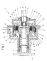
- Fig. 1 shows a drive unit largely in longitudinal section.
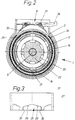
- Fig. 2 shows a section along the line I-I in Fig. 1 again.
- Fig. 3 is a plan view of the ring with the scenes in a single representation.
- the drive unit 1 shown in Fig. 1 consists of a drive shaft 5 and an output shaft 6, which are mounted concentrically to one another in a housing 2 by means of bearings 3, 4, a coupling device 7 and a braking device 8.
- the drive shaft 5 is at one end by a not shown Driven by the power source and at the other end has a bore 9 for receiving a pin 10 of the output shaft 6 which is supported by means of a needle bearing 11.
- the clutch device 7 consists of a clutch part 13 mounted on the output shaft 6 in a rotationally fixed and axially displaceable manner, a compression spring 14 acting axially thereon, a multi-plate clutch 15 and a clutch part 16 which is fixedly connected to the drive shaft 5.
- the multi-plate clutch 15 has a number between the pressing surfaces 17, 18 arranged plates 19, 20, wherein the outer plates 19 engage in the driver 21 of the coupling part 16 and the inner plates in the driver 22.
- the driver 22 is rotatably connected to the output shaft 6 and held axially by the nut 23.
- the pressing surfaces 17 and 18 are formed by the end faces of the coupling part 13 and the disk 25 held on the driver 22 by means of a ring 24.
- the axially displaceable coupling part 13 carries on the outside a ring 27 which is rotatably mounted by means of a bearing bush 26.
- the ring 27 shown in more detail in FIG.
- the scenes 28 are formed symmetrically with respect to the axis of the ring 27 by increasing control surfaces 29 and stops 30.
- the end face (31) of the ring (27) opposite the scenes 28 is supported in the housing (2), with one releaser (32) in the scenes (28), one radially in the illustrated embodiment Coupling part (13) bearing bolt (33) with its cylindrical surface (34).
- the braking device (8) is supported against rotation by bolts (37) in the housing (2) and actuated by means of a cable (38).
- the drive shaft (5) drives the output shaft (6) via the multi-plate clutch (15) which is engaged by the force of the compression spring (14).
- the releasers (32) rest against the scenes (28) with little play.
- the braking device (8) is actuated, the braking of the ring (27) pivots it relative to the coupling part (13), as a result of which the releasers run up on the rising surfaces (29) of the links (28) and the multi-plate clutch (15) by axial displacement of the coupling part (13) releases.
- the multi-plate clutch (15) is completely released when the releasers (32) bear against the stops (30) of the links (28). In this case the output shaft (6) is fully braked.
- this device according to the invention is possible both for steering devices on single-axle vehicles and for other drives in vehicle and mechanical engineering.
Landscapes
- Engineering & Computer Science (AREA)
- General Engineering & Computer Science (AREA)
- Mechanical Engineering (AREA)
- Chemical & Material Sciences (AREA)
- Combustion & Propulsion (AREA)
- Transportation (AREA)
- Braking Arrangements (AREA)
- Mechanical Operated Clutches (AREA)
Applications Claiming Priority (2)
| Application Number | Priority Date | Filing Date | Title |
|---|---|---|---|
| AT169292A AT397546B (de) | 1992-08-21 | 1992-08-21 | Kupplungs- und bremseinrichtung |
| AT1692/92 | 1992-08-21 |
Publications (1)
| Publication Number | Publication Date |
|---|---|
| EP0585214A1 true EP0585214A1 (fr) | 1994-03-02 |
Family
ID=3518939
Family Applications (1)
| Application Number | Title | Priority Date | Filing Date |
|---|---|---|---|
| EP93890159A Withdrawn EP0585214A1 (fr) | 1992-08-21 | 1993-08-19 | Dispositif d'embrayage et de freinage |
Country Status (4)
| Country | Link |
|---|---|
| EP (1) | EP0585214A1 (fr) |
| AT (1) | AT397546B (fr) |
| CZ (1) | CZ169793A3 (fr) |
| SK (1) | SK89593A3 (fr) |
Cited By (1)
| Publication number | Priority date | Publication date | Assignee | Title |
|---|---|---|---|---|
| EP0897072A3 (fr) * | 1997-08-13 | 2001-11-28 | REFORM-WERKE BAUER & CO. GESELLSCHAFT M.B.H. | Dispositif d'embrayage et de frein pour un groupe propulseur |
Citations (4)
| Publication number | Priority date | Publication date | Assignee | Title |
|---|---|---|---|---|
| DE498780C (de) * | 1930-05-27 | Koehring Co | Lenkvorrichtung fuer Gleiskettenfahrzeuge mit zwei ausrueckbaren Kupplungen | |
| FR878085A (fr) * | 1941-08-14 | 1943-01-11 | Dispositif de changement de direction à débrayages commandés pour tracteurs ou autres véhicules | |
| FR1060318A (fr) * | 1951-10-25 | 1954-04-01 | Eisenwerk Weserhu Tte A G | Accouplement à friction à disques |
| CH629432A5 (en) * | 1978-06-02 | 1982-04-30 | Johann Nussmueller | Steering device on a machine |
-
1992
- 1992-08-21 AT AT169292A patent/AT397546B/de not_active IP Right Cessation
-
1993
- 1993-08-18 CZ CZ931697A patent/CZ169793A3/cs unknown
- 1993-08-19 SK SK89593A patent/SK89593A3/sk unknown
- 1993-08-19 EP EP93890159A patent/EP0585214A1/fr not_active Withdrawn
Patent Citations (4)
| Publication number | Priority date | Publication date | Assignee | Title |
|---|---|---|---|---|
| DE498780C (de) * | 1930-05-27 | Koehring Co | Lenkvorrichtung fuer Gleiskettenfahrzeuge mit zwei ausrueckbaren Kupplungen | |
| FR878085A (fr) * | 1941-08-14 | 1943-01-11 | Dispositif de changement de direction à débrayages commandés pour tracteurs ou autres véhicules | |
| FR1060318A (fr) * | 1951-10-25 | 1954-04-01 | Eisenwerk Weserhu Tte A G | Accouplement à friction à disques |
| CH629432A5 (en) * | 1978-06-02 | 1982-04-30 | Johann Nussmueller | Steering device on a machine |
Cited By (1)
| Publication number | Priority date | Publication date | Assignee | Title |
|---|---|---|---|---|
| EP0897072A3 (fr) * | 1997-08-13 | 2001-11-28 | REFORM-WERKE BAUER & CO. GESELLSCHAFT M.B.H. | Dispositif d'embrayage et de frein pour un groupe propulseur |
Also Published As
| Publication number | Publication date |
|---|---|
| CZ169793A3 (en) | 1994-03-16 |
| AT397546B (de) | 1994-04-25 |
| ATA169292A (de) | 1993-09-15 |
| SK89593A3 (en) | 1994-04-06 |
Similar Documents
| Publication | Publication Date | Title |
|---|---|---|
| DE69714183T2 (de) | Sperrdifferential mit Reibkupplungselementen | |
| DE3031643A1 (de) | Servoeinrichtung, insbesondere zur bremskraftverstaerkung in einem kraftfahrzeug | |
| DE3225425C2 (fr) | ||
| DE3536943C2 (fr) | ||
| DE10251467A1 (de) | Getriebemodul für Kupplungsbetätigungseinrichtung einer Differentialanordnung | |
| DE3822115A1 (de) | Klauenkupplungsmechanismus | |
| DE2262623A1 (de) | Kupplungs- und parkbremsenanordnung fuer den endantrieb eines laderfahrzeugs oder dergl. mit hydrostatischem antrieb | |
| DE2235107C3 (de) | Ausgleichsgetriebe mit selbsttätiger Sperrung | |
| DE2921547C2 (de) | Kraftuebertragungsmechanismus fuer fahrzeuge | |
| EP1772645B1 (fr) | Dispositif d'embrayage pour un véhicule automobile | |
| DE2361019C2 (de) | Lösbare starre Kupplung | |
| DE1530780B1 (de) | Einrichtung zum Ein- und Ausruecken der Reibungskupplung von Kraftfahrzeugen | |
| DE831507C (de) | Mechanisches Kraftwagengetriebe mit selbsttaetig schaltender Motorkupplung | |
| DE602004009114T2 (de) | Kupplung | |
| AT397546B (de) | Kupplungs- und bremseinrichtung | |
| DE19532590B4 (de) | Motor- und handbetätigbarer Stellantrieb | |
| EP0237840B1 (fr) | Dispositif de commande pour embrayage à friction pour le verrouillage d'un différentiel de véhicule | |
| AT404978B (de) | Kupplungs- und bremseinrichtung für eine antriebseinheit | |
| DE2211603A1 (de) | Reibungskupplung in wahlweiser ausfuehrung mit fliehkraft- oder manueller betaetigung, insbesondere fuer zweiradfahrzeuge | |
| EP1010911B1 (fr) | Dispositif de positionnement pour un embrayage à friction d'un véhicule automobile | |
| DE3327984C2 (fr) | ||
| DE1505944B2 (de) | Überlast-Scheibenreibungskupplung | |
| DE10314219A1 (de) | Überlastkupplung | |
| DE102008051287B4 (de) | Fahrzeuglenksystem mit Hilfskraftlenkung | |
| EP0949429A2 (fr) | Dispositif de commande de secours pour un actionneur à moteur électrique |
Legal Events
| Date | Code | Title | Description |
|---|---|---|---|
| PUAI | Public reference made under article 153(3) epc to a published international application that has entered the european phase |
Free format text: ORIGINAL CODE: 0009012 |
|
| AK | Designated contracting states |
Kind code of ref document: A1 Designated state(s): AT CH DE FR GB IT LI |
|
| STAA | Information on the status of an ep patent application or granted ep patent |
Free format text: STATUS: THE APPLICATION IS DEEMED TO BE WITHDRAWN |
|
| 18D | Application deemed to be withdrawn |
Effective date: 19940903 |