EP0585455B1 - Lineare orthopaedische vorrichtung fuer externe fixation - Google Patents
Lineare orthopaedische vorrichtung fuer externe fixation Download PDFInfo
- Publication number
- EP0585455B1 EP0585455B1 EP93920538A EP93920538A EP0585455B1 EP 0585455 B1 EP0585455 B1 EP 0585455B1 EP 93920538 A EP93920538 A EP 93920538A EP 93920538 A EP93920538 A EP 93920538A EP 0585455 B1 EP0585455 B1 EP 0585455B1
- Authority
- EP
- European Patent Office
- Prior art keywords
- rods
- rod
- plugs
- linear
- external setting
- Prior art date
- Legal status (The legal status is an assumption and is not a legal conclusion. Google has not performed a legal analysis and makes no representation as to the accuracy of the status listed.)
- Expired - Lifetime
Links
- 230000000399 orthopedic effect Effects 0.000 title abstract description 6
- 210000000988 bone and bone Anatomy 0.000 claims abstract description 17
- 239000007787 solid Substances 0.000 claims abstract description 16
- 230000000903 blocking effect Effects 0.000 claims abstract description 4
- 239000000463 material Substances 0.000 claims description 5
- 230000005611 electricity Effects 0.000 claims description 3
- 230000008878 coupling Effects 0.000 abstract 1
- 238000010168 coupling process Methods 0.000 abstract 1
- 238000005859 coupling reaction Methods 0.000 abstract 1
- 206010017076 Fracture Diseases 0.000 description 13
- 208000010392 Bone Fractures Diseases 0.000 description 8
- 238000007596 consolidation process Methods 0.000 description 5
- 238000001356 surgical procedure Methods 0.000 description 5
- 238000005553 drilling Methods 0.000 description 4
- 238000010079 rubber tapping Methods 0.000 description 4
- 239000000470 constituent Substances 0.000 description 3
- 230000000712 assembly Effects 0.000 description 2
- 238000000429 assembly Methods 0.000 description 2
- 238000002513 implantation Methods 0.000 description 2
- 208000014674 injury Diseases 0.000 description 2
- 239000002184 metal Substances 0.000 description 2
- 238000012544 monitoring process Methods 0.000 description 2
- 230000008733 trauma Effects 0.000 description 2
- 208000024779 Comminuted Fractures Diseases 0.000 description 1
- 238000005481 NMR spectroscopy Methods 0.000 description 1
- 238000006073 displacement reaction Methods 0.000 description 1
- 230000009977 dual effect Effects 0.000 description 1
- 239000000834 fixative Substances 0.000 description 1
- 239000012634 fragment Substances 0.000 description 1
- 239000007943 implant Substances 0.000 description 1
- 230000007774 longterm Effects 0.000 description 1
- 230000005389 magnetism Effects 0.000 description 1
- 238000002601 radiography Methods 0.000 description 1
- 230000001954 sterilising effect Effects 0.000 description 1
- 238000004659 sterilization and disinfection Methods 0.000 description 1
Images



Classifications
-
- A—HUMAN NECESSITIES
- A61—MEDICAL OR VETERINARY SCIENCE; HYGIENE
- A61B—DIAGNOSIS; SURGERY; IDENTIFICATION
- A61B17/00—Surgical instruments, devices or methods
- A61B17/56—Surgical instruments or methods for treatment of bones or joints; Devices specially adapted therefor
- A61B17/58—Surgical instruments or methods for treatment of bones or joints; Devices specially adapted therefor for osteosynthesis, e.g. bone plates, screws or setting implements
- A61B17/60—Surgical instruments or methods for treatment of bones or joints; Devices specially adapted therefor for osteosynthesis, e.g. bone plates, screws or setting implements for external osteosynthesis, e.g. distractors, contractors
- A61B17/64—Devices extending alongside the bones to be positioned
- A61B17/6416—Devices extending alongside the bones to be positioned with non-continuous, e.g. hinged, pin-clamp connecting element
-
- A—HUMAN NECESSITIES
- A61—MEDICAL OR VETERINARY SCIENCE; HYGIENE
- A61B—DIAGNOSIS; SURGERY; IDENTIFICATION
- A61B17/00—Surgical instruments, devices or methods
- A61B17/56—Surgical instruments or methods for treatment of bones or joints; Devices specially adapted therefor
- A61B17/58—Surgical instruments or methods for treatment of bones or joints; Devices specially adapted therefor for osteosynthesis, e.g. bone plates, screws or setting implements
- A61B17/60—Surgical instruments or methods for treatment of bones or joints; Devices specially adapted therefor for osteosynthesis, e.g. bone plates, screws or setting implements for external osteosynthesis, e.g. distractors, contractors
-
- A—HUMAN NECESSITIES
- A61—MEDICAL OR VETERINARY SCIENCE; HYGIENE
- A61B—DIAGNOSIS; SURGERY; IDENTIFICATION
- A61B17/00—Surgical instruments, devices or methods
- A61B2017/00831—Material properties
- A61B2017/00902—Material properties transparent or translucent
Definitions
- the present invention relates to a linear external fixator for orthopedic surgery to reduce a fracture and immobilize a fractured bone.
- Osteosynthesis using an external fixator has been widely developed over the past ten years, notably for war surgery. Its use is necessary for open or complex fractures of the limbs, particularly whenever an intra focal osteosynthesis is contraindicated.
- the fixator proposed by the invention is linear and compatible with certain linear or circular fixators used in orthopedic and trauma surgery, especially war surgery. It is intended to be used by a mobile surgical antenna.
- the first quality that a fixer must have is mechanical rigidity. Indeed, its role being to favor the consolidation of the bone fragments of a fracture, it must ensure the strict immobilization of these.
- fixators must allow rapid intervention by the surgeons and to do this, their manipulation must be easy in all cases of fractures.
- radiolucency and non-magnetism can greatly facilitate the monitoring of bone consolidation.
- Linear external fixers consist of a rigid metal tube, having in diametrically opposed orifices regularly spaced and threaded in two perpendicular planes, in which the plugs are engaged and locked by screws.
- Patent FR 2457676 describes a linear fixator making it possible to reduce and contain a fracture. It comprises a tube-shaped support carrying two segments of tubes having in two planes mutually perpendicular diametrically opposed orifices regularly spaced and threaded intended for pins or plugs. The tube segments are assembled with the support using spherical ball joints. These ball joints are extended by collars whose sliding on the support causes the displacement of the two segments of perforated tubes to allow reduction and containment of the fracture. These devices designed to be worn by patients who are in motion have several drawbacks. The ball joints that tighten and lock the pins engaged in the bone tend to loosen during the patients' walking movements and therefore do not ensure good reduction and immobilization of the bone during consolidation.
- the device requires five basic components: support, tube, ball joint, collar, pin or plug; it does not allow easy handling, because of the high number of its basic constituents.
- This fixator includes supports or connecting rods which allow the parts carrying the pins to be assembled by means of ball joints and collars. It must completely frame the injured limb, and therefore does not have the flexibility of using linear fixators, whose basic system is a rod or beam parallel to the bone. These rods or beams can be assembled in scaffolding and oriented in all directions relative to each other to allow the treatment of the most complicated cases, such as comminuted fractures.
- fixer described in this patent has a number of basic constituents, still too large.
- the object of the invention is therefore to propose a linear fixer having the equivalent characteristics of the known fixer and described by patent FR 2457676 without its drawbacks. It has better rigidity because it ensures a tightening of the plugs on the rods more efficient, therefore better immobilization of the bone. It is lighter and radiolucent. In addition to radiolucency, it is non-magnetic and does not conduct electricity. It has a simplicity of assembly which makes it suitable for war or disaster surgery. It is therefore designed to facilitate manipulation by the surgeon and allow monitoring of bone consolidation.
- fixer is equipped with self-drilling and self-tapping plugs of different diameters adapted to the implantation site.
- the invention therefore relates to a linear orthopedic device for external fixation of fractures, comprising at least one solid rigid rod having transverse orifices for the passage of the plugs screwed into the bone on either side of the fracture focal point and fixed securely to the cards by means which secure them.
- This structure has the advantage of having a very high rigidity due to the fact that the rod is full and of bringing into play a number of basic constituents reduced to three: rod, plug, means for joining them together.
- the rod carrying the cards is here freed from a support, unlike the systems described in the two patents cited above.
- the invention also relates to a fixer as defined above, further characterized in that the material constituting the rods, plugs and certain elements of the means which secure them is radio-transparent, non-magnetic and non-conductive of electricity .
- the consolidation of the bone can therefore be followed by radiography, nuclear magnetic resonance. Electrophysiological explorations are also facilitated.
- the means which secure the plug to the rod are clamps provided with locking means.
- the means which secure the plug to the rod are fixing inserts, in order to minimize the bulk. These inserts have variable diameters, depending on the type of plug used.
- the solid rigid rod consists of two rigid longitudinal solid half-rods, having notches for the passage of the plugs and assembled by clamps provided with locking means.
- This variant has the advantage of making it possible to carry out more complex assemblies, or to resume assemblies for lack of reduction because it offers the possibility of keeping the initial implantation of the cards in the bone, which is an important point for patients whose bone capital or implant sites may be limited by the damage caused by the trauma.
- Another advantage of the invention lies in its great flexibility of use and the possibility of easily modifying the geometry of the assembly.
- the invention is suitable for all cases of fractures, which makes its use universal.
- the hose clamps are snap-in for a better hold of the system and ensure greater safety for the patient. They are fitted with self-locking braked bolts for the same purpose.
- the fixator is characterized in that it comprises several rods assembled in a complex assembly or "scaffolding" by means of collars associated two by two and blocked in the same manner as above.
- the fixer according to the invention can be provided with plugs of suitable diameter which are both self-drilling and self-tapping. Thus, there is no prior drilling of the bone by a drill bit, the plugs being able to carry out both the perforation and the tapping of the bone structure.
- Figure 1 shows a sectional view of a solid rod having transverse orifices 2 regularly spaced over the entire length of the rod.
- frustoconical opening 3 intended to allow the passage of the plug provided with a means for securing it to the rod, such as a fixing insert 6.
- FIG. 2 shows a solid rod 1 provided with plugs 4 and clamps 5 and 5 'provided with locking means.
- the plugs 4 are engaged in the cylindrical housings 2 of the rod 1. They are held in place by fastening means of two types: fastening inserts 6 inserted in the rods and coaxial with respect to the plugs as shown diagrammatically in FIG. 3 and clamps 5 as shown diagrammatically on Figure 4 which are additional means of fixing the plugs, to ensure maximum versatility of the fixer.
- the fixing inserts have, over their half length, blades 9 which allow them to be inserted by force into the orifices 2 in which they take place around the plugs.
- the operator can use additional means to secure the plugs to the rods, such as the clamps 5 of Figure 4 provided with locking means.
- These collars 5 made of radiolucent material preferably have a rough surface in order to adhere to the rod. They cannot slide on the rod and are snap-on. They have a clamping flange 7 for enclosing the rod 1 with which is associated a cylindrical locking sleeve 8, which allows the clamping of the collar by screwing.
- the sleeve 8 has a threaded portion 10 intended to receive the thread of a bolt 11.
- the bolt 11 is such that it is braked in its loosening and comprises an automatic blocking.
- the use of the collar 5 therefore provides the fixator with a versatility in implanting the plugs 4.
- the clamp comprises for this purpose a second flange 12 which encloses the plug 4 offset.
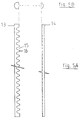
- FIG. 5A shows an alternative embodiment of the fixer according to the invention.
- the solid rod 1 here consists of two dissimilar longitudinal half-rods, one of which 13 has recesses 15 regularly spaced, with a rounded bottom. The union of these two half-rods forms a rod full notched full whose notches or housings are intended to receive the cards 4.
- the half-rod 14 has a rectangular recess over its entire length, so that this recess can fit onto the projecting parts 16 opposite the half-rod 13.
- Figure 2 outlines an assembly of two rods 1 and 1 'using a union collar 5'.
- This 5 'union collar shown in Figure 6 consists of two simple collars articulated around their clamping axis relative to each other on their common surfaces 17 and 17' which have the distinction of being rough .
- the bolt 18 has a length twice that of the single collar.
- the simple collars of this union collar can rotate relative to each other around the axis of the bolt 18 before tightening thereof and are locked by screwing in the chosen orientation.
- the bolt 18 has the dual function of securing the collars with the rods and the collars between them.
- the fixative is intended to equip mobile surgical antennas and is presented in a blister after sterilization by gamma rays, which allows only the useful elements to be sterilized. It is intended for single use.
- the surgeon guided by the perforated rod which serves as a viewfinder through which the soft part perforator slides causes the self-drilling and self-tapping sheets 4 to penetrate into the bone structure. Then he sets up the different sheets by sliding them into the housings of the rod 1. He then proceeds to block the sheets according to the means described above.
- an offset plug by tilting it with respect to the axis perpendicular to the rod and in this case the plug is held in place by a plug clamp.
Landscapes
- Health & Medical Sciences (AREA)
- Orthopedic Medicine & Surgery (AREA)
- Life Sciences & Earth Sciences (AREA)
- Surgery (AREA)
- Medical Informatics (AREA)
- Engineering & Computer Science (AREA)
- Biomedical Technology (AREA)
- Heart & Thoracic Surgery (AREA)
- Nuclear Medicine, Radiotherapy & Molecular Imaging (AREA)
- Molecular Biology (AREA)
- Animal Behavior & Ethology (AREA)
- General Health & Medical Sciences (AREA)
- Public Health (AREA)
- Veterinary Medicine (AREA)
- Surgical Instruments (AREA)
- Orthopedics, Nursing, And Contraception (AREA)
- Prostheses (AREA)
Claims (5)
- Gerade orthophädische Vorrichtung zur externen Fixation, die es ermöglicht, bei Knochenbrüchen zu repositionieren und einen gebrochenen Knochen ruhigzustellen, umfassend zumindest einen starren, einstückigen Schaft (1), der über seine gesamte Länge gleichmäßig voneinander beabstandete Querlöcher aufweist, um eine Vielzahl Stifte (4) hindurchzuführen, ausgestattet mit Festmachmitteln (6,5), um ihn mit diesen Stiften (4) fest zu verbinden, dadurch gekennzeichnet, daß die Schäfte massiv sind und daß die Mittel zum festen Verbinden der Schäfte (1) mit den Stiften (4) mit Verriegelungsmitteln (8,11) versehene Schnapp-Klemmschellen (5) oder bezogen auf die Stifte (4) koaxiale Befestigungseinsätze (6) sind, wobei die Schäfte (1), die Stifte (4) und die Mittel (6,5), um die Schäfte fest mit den Stiften (4) zu verbinden, aus Materialien bestehen, die gleichzeitig strahlendurchlässig, nichtmagnetisch und nichtleitend sind.
- Gerade orthophädische Vorrichtung zur externen Fixation nach Anspruch 1, dadurch gekennzeichnet, daß der Außendurchmesser der Befestigungseinsätze (6) variabel ist, sodaß er sich an den Durchmesser der Stifte (4) anpaßt.
- Gerade orthopädische Vorrichtung zur externen Fixation nach Anspruch 1, dadurch gekennzeichnet, daß die Querlöcher des massiven Schafts (1) kegelstumpfförmige Öffnungen (3) darstellen.
- Gerade orthopädische Vorrichtung zur externen Fixation nach Anspruch 1, die aus zwei länglichen massiven starren Halbschäften (13,14) besteht, dadurch gekennzeichnet, daß nur einer der Halbschäfte regelmäßig verteilte Vertiefungen (15) mit abgerundetem Boden aufweist, die eine Rastung des Schaftes (1) definieren.
- Gerade orthopädische Vorrichtung zur externen Fixation nach Anspruch 1 und 4, dadurch gekennzeichnet, daß die beiden länglichen Halbschäfte (13,14), die den massiven starren Schaft (1) bilden, durch zumindest eine Klemmschelle (5) aneinandergefügt sind, die mit einem Verriegelungsmittel (8,11) versehen ist.
Applications Claiming Priority (3)
| Application Number | Priority Date | Filing Date | Title |
|---|---|---|---|
| FR9203275A FR2688685B1 (fr) | 1992-03-19 | 1992-03-19 | Appareil orthopedique lineaire de fixation externe. |
| FR9203275 | 1992-03-19 | ||
| PCT/FR1993/000278 WO1993018717A1 (fr) | 1992-03-19 | 1993-03-19 | Appareil orthopedique lineaire de fixation externe |
Publications (2)
| Publication Number | Publication Date |
|---|---|
| EP0585455A1 EP0585455A1 (de) | 1994-03-09 |
| EP0585455B1 true EP0585455B1 (de) | 1997-09-03 |
Family
ID=9427822
Family Applications (1)
| Application Number | Title | Priority Date | Filing Date |
|---|---|---|---|
| EP93920538A Expired - Lifetime EP0585455B1 (de) | 1992-03-19 | 1993-03-19 | Lineare orthopaedische vorrichtung fuer externe fixation |
Country Status (5)
| Country | Link |
|---|---|
| EP (1) | EP0585455B1 (de) |
| AT (1) | ATE157524T1 (de) |
| DE (1) | DE69313565T2 (de) |
| FR (1) | FR2688685B1 (de) |
| WO (1) | WO1993018717A1 (de) |
Families Citing this family (3)
| Publication number | Priority date | Publication date | Assignee | Title |
|---|---|---|---|---|
| FR2725613B1 (fr) * | 1994-10-12 | 1997-03-14 | Hardy Jean Marie | Fixateur externe applicable en orthopedie et en traumatologie |
| FR2787697B1 (fr) | 1998-12-29 | 2001-06-15 | France Etat | Dispositif orthopedique monolateral de fixation externe pour l'immobilisation d'un os fracture |
| CN106214274B (zh) * | 2016-09-25 | 2018-07-17 | 青岛市妇女儿童医院 | 一种手术用针头的固定装置 |
Family Cites Families (7)
| Publication number | Priority date | Publication date | Assignee | Title |
|---|---|---|---|---|
| BE389476A (de) * | ||||
| FR1206411A (fr) * | 1958-08-22 | 1960-02-09 | Appareil externe pour réduction des fractures du tibia | |
| DE2745504A1 (de) * | 1977-10-10 | 1979-04-19 | Erich Strickle | Vorrichtung zur ruhigstellung oder stuetzung von gliedmassen von menschen und tieren |
| FR2499400A1 (fr) * | 1981-02-06 | 1982-08-13 | Tornier Sa | Fixateur perfectionne pour fractures complexes, et notamment du type epiphysaire |
| FR2553994B1 (fr) * | 1983-10-27 | 1987-09-04 | Sorem Soc Realisa Elect Mec | Appareils orthopediques pour immobiliser un os fracture |
| DE3515678A1 (de) * | 1985-05-02 | 1986-11-06 | Thomas Dr.med. 6903 Neckargemünd Schewior | Vorrichtung zum befestigen und spannen von fixateur externe-bauteilen |
| DE3611319A1 (de) * | 1986-04-04 | 1987-10-15 | Witzel Ulrich | Fixateur externe zur osteosynthese |
-
1992
- 1992-03-19 FR FR9203275A patent/FR2688685B1/fr not_active Expired - Fee Related
-
1993
- 1993-03-19 DE DE69313565T patent/DE69313565T2/de not_active Expired - Fee Related
- 1993-03-19 WO PCT/FR1993/000278 patent/WO1993018717A1/fr not_active Ceased
- 1993-03-19 EP EP93920538A patent/EP0585455B1/de not_active Expired - Lifetime
- 1993-03-19 AT AT93920538T patent/ATE157524T1/de not_active IP Right Cessation
Also Published As
| Publication number | Publication date |
|---|---|
| WO1993018717A1 (fr) | 1993-09-30 |
| EP0585455A1 (de) | 1994-03-09 |
| FR2688685A1 (fr) | 1993-09-24 |
| DE69313565D1 (de) | 1997-10-09 |
| ATE157524T1 (de) | 1997-09-15 |
| FR2688685B1 (fr) | 1998-03-13 |
| DE69313565T2 (de) | 1998-04-02 |
Similar Documents
| Publication | Publication Date | Title |
|---|---|---|
| EP1056407B1 (de) | Orthopädischer monolateraler aussenfixateur | |
| EP0443894B1 (de) | Osteosynthesevorrichtung zur Berichtigung der Verformungen der Wirbelsäule | |
| EP1872731B1 (de) | Implantat zur Stabilisierung der Lumbosakralregion | |
| CA2133766C (fr) | Dispositif d'osteosynthese rachidienne | |
| EP0235138B1 (de) | Richtgerät zum fixieren von knochenbrüchen | |
| EP0514303B1 (de) | Verriegelbares Verbindungsstück für Verankerungselemente für die Wirbelsäulenosteosynthese | |
| CA2362247C (fr) | Dispositif de distraction/contraction pour systeme d'osteosynthese rachidienne | |
| EP0140790B1 (de) | Vorrichtung zur dynamischen Verbesserung der Rückgratsmissgestaltungen | |
| EP0414633B1 (de) | Dynamische Aussenbefestigung für das Handgelenk | |
| EP0194187A1 (de) | Orthopädische Vorrichtung zur äusseren Fixierung von Knochen | |
| FR2784282A1 (fr) | Systeme d'osteosynthese rachidienne a rigidite amelioree | |
| FR2683446A1 (fr) | Fixateur externe modulaire pour immobilisation d'un foyer de fracture. | |
| EP1075224A1 (de) | Wirbelsäulen-osteosynthesesystem mit spannvorrichtung, insbesondere zur vorderen fixierung | |
| FR2573977A1 (fr) | Appareil orthopedique de fixation externe, notamment pour le positionnement des os fractures | |
| FR2833151A1 (fr) | Implant d'ancrage osseux a tete polyaxiale | |
| WO1993008747A1 (fr) | Procede et dispositif pour bloquer un fil en coeliochirurgie | |
| FR2499400A1 (fr) | Fixateur perfectionne pour fractures complexes, et notamment du type epiphysaire | |
| FR2983696A1 (fr) | Systeme de pincement osseux | |
| EP0585455B1 (de) | Lineare orthopaedische vorrichtung fuer externe fixation | |
| FR3099694A1 (fr) | Fixateur de volet crânien. | |
| FR2769490A1 (fr) | Dispositif de fixation d'une tige dans une paroi osseuse mince | |
| FR2720262A1 (fr) | Dispositif d'ostéosynthèse à coapteurs rapportés. | |
| WO2015092270A1 (fr) | Système de correction rachidien | |
| FR2855040A1 (fr) | Dispositif de distraction osseuse particulierement adapte au doigt et dispositif pret a monter | |
| FR2674120A1 (fr) | Fixateur pour intervention orthopedique, notamment pour les osteosyntheses de la main. |
Legal Events
| Date | Code | Title | Description |
|---|---|---|---|
| PUAI | Public reference made under article 153(3) epc to a published international application that has entered the european phase |
Free format text: ORIGINAL CODE: 0009012 |
|
| AK | Designated contracting states |
Kind code of ref document: A1 Designated state(s): AT BE CH DE ES GB IT LI SE |
|
| 17P | Request for examination filed |
Effective date: 19940317 |
|
| 17Q | First examination report despatched |
Effective date: 19950620 |
|
| GRAG | Despatch of communication of intention to grant |
Free format text: ORIGINAL CODE: EPIDOS AGRA |
|
| GRAH | Despatch of communication of intention to grant a patent |
Free format text: ORIGINAL CODE: EPIDOS IGRA |
|
| GRAH | Despatch of communication of intention to grant a patent |
Free format text: ORIGINAL CODE: EPIDOS IGRA |
|
| GRAA | (expected) grant |
Free format text: ORIGINAL CODE: 0009210 |
|
| AK | Designated contracting states |
Kind code of ref document: B1 Designated state(s): AT BE CH DE ES GB IT LI SE |
|
| PG25 | Lapsed in a contracting state [announced via postgrant information from national office to epo] |
Ref country code: GB Free format text: LAPSE BECAUSE OF FAILURE TO SUBMIT A TRANSLATION OF THE DESCRIPTION OR TO PAY THE FEE WITHIN THE PRESCRIBED TIME-LIMIT Effective date: 19970903 Ref country code: ES Free format text: THE PATENT HAS BEEN ANNULLED BY A DECISION OF A NATIONAL AUTHORITY Effective date: 19970903 |
|
| REF | Corresponds to: |
Ref document number: 157524 Country of ref document: AT Date of ref document: 19970915 Kind code of ref document: T |
|
| REG | Reference to a national code |
Ref country code: CH Ref legal event code: EP |
|
| REF | Corresponds to: |
Ref document number: 69313565 Country of ref document: DE Date of ref document: 19971009 |
|
| ITF | It: translation for a ep patent filed | ||
| PG25 | Lapsed in a contracting state [announced via postgrant information from national office to epo] |
Ref country code: SE Effective date: 19971203 |
|
| GBV | Gb: ep patent (uk) treated as always having been void in accordance with gb section 77(7)/1977 [no translation filed] |
Effective date: 19970903 |
|
| PLBE | No opposition filed within time limit |
Free format text: ORIGINAL CODE: 0009261 |
|
| STAA | Information on the status of an ep patent application or granted ep patent |
Free format text: STATUS: NO OPPOSITION FILED WITHIN TIME LIMIT |
|
| 26N | No opposition filed | ||
| PGFP | Annual fee paid to national office [announced via postgrant information from national office to epo] |
Ref country code: CH Payment date: 20020218 Year of fee payment: 10 |
|
| PGFP | Annual fee paid to national office [announced via postgrant information from national office to epo] |
Ref country code: BE Payment date: 20020314 Year of fee payment: 10 |
|
| PGFP | Annual fee paid to national office [announced via postgrant information from national office to epo] |
Ref country code: AT Payment date: 20020321 Year of fee payment: 10 |
|
| PGFP | Annual fee paid to national office [announced via postgrant information from national office to epo] |
Ref country code: DE Payment date: 20020429 Year of fee payment: 10 |
|
| PG25 | Lapsed in a contracting state [announced via postgrant information from national office to epo] |
Ref country code: AT Free format text: LAPSE BECAUSE OF NON-PAYMENT OF DUE FEES Effective date: 20030319 |
|
| PG25 | Lapsed in a contracting state [announced via postgrant information from national office to epo] |
Ref country code: LI Free format text: LAPSE BECAUSE OF NON-PAYMENT OF DUE FEES Effective date: 20030331 Ref country code: CH Free format text: LAPSE BECAUSE OF NON-PAYMENT OF DUE FEES Effective date: 20030331 Ref country code: BE Free format text: LAPSE BECAUSE OF NON-PAYMENT OF DUE FEES Effective date: 20030331 |
|
| BERE | Be: lapsed |
Owner name: *LONIEWSKI XAVIER Effective date: 20030331 |
|
| PG25 | Lapsed in a contracting state [announced via postgrant information from national office to epo] |
Ref country code: DE Free format text: LAPSE BECAUSE OF NON-PAYMENT OF DUE FEES Effective date: 20031001 |
|
| REG | Reference to a national code |
Ref country code: CH Ref legal event code: PL |
|
| PG25 | Lapsed in a contracting state [announced via postgrant information from national office to epo] |
Ref country code: IT Free format text: LAPSE BECAUSE OF NON-PAYMENT OF DUE FEES;WARNING: LAPSES OF ITALIAN PATENTS WITH EFFECTIVE DATE BEFORE 2007 MAY HAVE OCCURRED AT ANY TIME BEFORE 2007. THE CORRECT EFFECTIVE DATE MAY BE DIFFERENT FROM THE ONE RECORDED. Effective date: 20050319 |