EP0585513B1 - Verfahrenssteuerungssystem mit Simultaneitätstabelle - Google Patents
Verfahrenssteuerungssystem mit Simultaneitätstabelle Download PDFInfo
- Publication number
- EP0585513B1 EP0585513B1 EP92870140A EP92870140A EP0585513B1 EP 0585513 B1 EP0585513 B1 EP 0585513B1 EP 92870140 A EP92870140 A EP 92870140A EP 92870140 A EP92870140 A EP 92870140A EP 0585513 B1 EP0585513 B1 EP 0585513B1
- Authority
- EP
- European Patent Office
- Prior art keywords
- action
- time interval
- drawer
- control
- alarm
- Prior art date
- Legal status (The legal status is an assumption and is not a legal conclusion. Google has not performed a legal analysis and makes no representation as to the accuracy of the status listed.)
- Expired - Lifetime
Links
Images


Classifications
-
- G—PHYSICS
- G05—CONTROLLING; REGULATING
- G05B—CONTROL OR REGULATING SYSTEMS IN GENERAL; FUNCTIONAL ELEMENTS OF SUCH SYSTEMS; MONITORING OR TESTING ARRANGEMENTS FOR SUCH SYSTEMS OR ELEMENTS
- G05B19/00—Program-control systems
- G05B19/02—Program-control systems electric
- G05B19/04—Program control other than numerical control, i.e. in sequence controllers or logic controllers
- G05B19/042—Program control other than numerical control, i.e. in sequence controllers or logic controllers using digital processors
-
- G—PHYSICS
- G04—HOROLOGY
- G04G—ELECTRONIC TIME-PIECES
- G04G15/00—Time-pieces comprising means to be operated at preselected times or after preselected time intervals
- G04G15/006—Time-pieces comprising means to be operated at preselected times or after preselected time intervals for operating at a number of different times
-
- G—PHYSICS
- G07—CHECKING-DEVICES
- G07C—TIME OR ATTENDANCE REGISTERS; REGISTERING OR INDICATING THE WORKING OF MACHINES; GENERATING RANDOM NUMBERS; VOTING OR LOTTERY APPARATUS; ARRANGEMENTS, SYSTEMS OR APPARATUS FOR CHECKING NOT PROVIDED FOR ELSEWHERE
- G07C9/00—Individual registration on entry or exit
- G07C9/30—Individual registration on entry or exit not involving the use of a pass
- G07C9/32—Individual registration on entry or exit not involving the use of a pass in combination with an identity check
- G07C9/33—Individual registration on entry or exit not involving the use of a pass in combination with an identity check by means of a password
Definitions
- the present invention relates to a programmable control system for controlling a sequence of operations in any process.
- a particular application of the system is the control of a sequence of operations automatically ensuring the control of the opening of a set of cash drawers.
- Controlling and protecting access to facilities is a problem that is becoming ever more acute to ensure the safety of property and people, if not security or the reliability of industrial processes.
- EP-A-475866 describes a door opening device comprising a control means accessible to an operator and processing means ensuring the management door opening operations.
- the objective of the invention is to remedy this fundamental deficiency of known systems and to carry out an effective and reliable control, not simply of access to a set of cash drawers or to an industrial process, but also of the '' programmable use of cash drawers or the programmable sequence of process steps.
- the invention also aims to achieve a control and a dynamic control programmable and reprogrammable in real time at the discretion of the user without requiring the intervention of a technician whatsoever, thus ensuring optimal protection and security. and personalized.
- a programmable control system for controlling the operations of a controlled process in which each operation must be activated within a predetermined time interval, said system comprising control means accessible to an operator and processing means for managing said operations of the process.
- control means is arranged to launch the request signals for all the operations of the controlled process
- processing means comprise a programmable memory in which is loaded a table of the states of the operations associated with a table of acceptances designating the operations which can be activated simultaneously and the operations which must be triggered automatically following the activation of any operation.
- the processing means further comprises means for consulting the acceptance table in response to each control signal received in a second predetermined time interval less than the first aforementioned time interval, and generating an operation authorization signal for each operation only when the acceptance table has given an acceptance signal, said means remaining awaiting a new control signal before the expiration of the second predetermined time interval in response to a refusal signal from the acceptances.
- the authorization signals of the operations are thus generated so that the operations of the controlled process can be executed according to a programmed imposed sequence.
- the predetermined period of time in which a confirmation signal must be generated cannot be less than a minimum period of time.
- a clock is provided to fix and program, in depending on the date or the type of calendar day, the time slot during which each step of the process can be activated, the signals representing the designation of the time slot validating the timers assigned to this step so as to allow the activation stage activity during the designated time slot only.
- a security key coupled to a secret code is provided to introduce into the system priority timers and an acceptance table intended to temporarily replace the parameters residing in memory so as to validate an activation of a step in the event of 'emergency.
- the system according to the invention is advantageously connected to communicate with a microcomputer of individual control or common to several systems, this control microcomputer can be of the portable individual computer type.
- This control microcomputer is used to load the memory with the parameters of the sequences of operations and to reload it in real time at the option of the authorized responsible operator.
- the system according to the invention provides optimal protection and personalized security thanks to an individual parameterization that can be programmed and reprogrammed in real time.
- control microcomputer can incorporate the parameter memory and / or the microcontroller of each of the systems controlled and that the microcontroller can be installed there in hardware form or in software form.
- the invention finds its application in various fields. In the field of security, it can control access to crates and safes and vaults, control routes and routes, delay access to sites and also be applied to surveillance and in the police and gendarmerie . In the industrial field, the invention finds its application in controlled processes and mention may be made, for example, of the petroleum, chemical, pharmaceutical and laboratory industries.
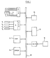
- Figure 1 is a block diagram of the general architecture of the system according to the invention in an application to a set of cash drawers.
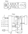
- Figure 2 is a schematic representation of the logical organization of the system.
- Figure 3 schematically shows a control panel on the front of the cabinet.
- FIG. 4 is a general diagram of the sequence of logical operations in the system of FIG. 1.
- Figure 5 is a diagram showing the sequence of logical states of a drawer.
- the system essentially comprises a control panel 11, a RAM memory 12 to be loaded with the tables of parameters relating to the constraints imposed on the sequence of operations and the tables of the states of the drawers as well as the tables of the routines specific to the drawers, a microcontroller 13, an erasable programmable memory EPROM 14 to contain the routines of command of the system, a real time clock 15 and an interface CFIA to carry out the communication with a microcomputer of control 16 , of the personal microcomputer type.
- the embodiment described by way of example includes four drawers designated T 1 , T 2 , T 3 , T 4 respectively. These drawers are associated with electrically controlled strikes generally represented by block G.
- the exchange of data and control signals is done, as is known, by means of interfaces such as PIA and ACIA and a communication bus 20.
- FIG. 2 The logical organization of the system is shown diagrammatically in FIG. 2. Before explaining the logical operation, the function of each functional block will be briefly described.
- the control panel is placed on the small drawer which the operator can open as soon as he has the key.
- it presents a display of the time slot for use H (see below), a button for canceling reset requests, buttons for requesting the opening of drawers D1 to D4 with associated indicator lights, an AL alarm button, a K lock for a security key and an RS232 connector for an external connection.
- the system parameters are loaded into memory, for example in the RAM 12 random access memory. These parameters are found in different tables.
- a LOT drawer status table includes three variables D, C and A for each drawer: D is in state 1 if the drawer has been requested to open, C is in state 1 if the request has been confirmed and accepted, and A is in state 1 if the drawer is open. When one of the three variables is at 1, the other variables for this drawer are automatically at O.
- An acceptance table the content of which is at least partially redundant with the state table, can also be provided.
- a SIM concurrency table specifies which drawers can be active at the same time.
- An automatic drawer activation table contains the numbers of the other drawers that the closing of a given drawer must open successively without request but with confirmation.
- the parameters t 1 and t 2 represent respectively the minimum time that the operator must wait before confirming his request and the time he has to confirm. If their values are zero, we consider that the request and confirmation operations to be carried out by the operator will be reduced to one.
- the parameters t 3 and t 4 cannot be canceled because the first is the time available to the operator to react and open the drawer and the second is the maximum opening time of the drawer.
- Parameters t 5 , t 6 and t 7 are also provided, which respectively represent the durations of the first and second pre-alarm phases and of the alarm phase. These parameters could also be set to zero.
- time slots are also loaded the time slots during which may or may not be opened or activated each drawer.
- the time slots are displayed on the control panel.
- the function of the microcontroller 13 is to multiplex the input signals (signals from the control panels, signals for the start and end of activity (opening) of the drawers and external input signals from the control microcomputer) and to execute the adequate routines to carry out the logical operations which will be described further on under the direction of the programmed routines residing in the EPROM memory 14.
- the link between the system and the microcomputer is not a fixed link; it can be a link established from a manager's microcomputer. So that the system can use these new parameters, the microcomputer control command interrupts the system, while leaving the system to process all requests in progress.
- the operation of the system according to the invention is based, for each drawer, on the occurrence of three events, namely: opening request, confirmation of the request and opening.
- eight states are defined for each drawer.
- FIG. 4 gives an overall view of these logical states, numbered from 0 to 7.
- States 0 to 4 are normal states, respectively rest, waiting, confirmation, opening, activity.
- the drawers can be located there independently of each other.
- States 5 to 7, respectively first pre-alarm, second pre-alarm and alarm, are common to all the drawers, i.e. all the drawers enter these states at the same time and leave these states at the same time time.
- a drawer is said to be in a state i, in accordance with the invention, if the stored time delay ti, i varying from 1 to 7.
- a drawer is in state 0 if it is in the rest state: it is then closed, is not the subject of any request or confirmation and the system is neither in pre-alarm nor in alarm.
- the corresponding drawer subsequently called Tk, is placed in state 1 if it was initially at rest.
- the lamp Lk is on.
- the drawer Tk After the incompressible time t 1 has elapsed, the drawer Tk automatically switches to state 2 (confirmation state). The Lk lamp flashes and the buzzer produces an intermittent sound. The operator has the time interval t 2 to confirm his request by pressing the push-button on the drawer Tk again. If the confirmation (C) is received before the expiration of the time interval t 2 , the microcontroller analyzes whether the drawer Tk can be opened by consulting the table of simultaneities SIM. If it can actually be opened (Y), the drawer Tk goes into state 3 (open state), its keeper G is supplied during the time interval t 3 , which is fixed at 7 seconds for example. If the drawer Tk is open (A) before the end of the time interval t 3 , the supply of the strike is immediately cut. The drawer is said to be in working condition (state 4).
- the drawer Tk If, at the end of the time interval t 3 , the drawer Tk has not been opened (A), it goes to state 2 and waits for a new confirmation signal during the time interval t 2 (the Lk lamp flashes again and the buzzer re-emits an intermittent sound) and so on until the drawer Tk has been opened or the time interval t 2 has elapsed, which is always calculated from from the end of the time interval t 1 . In the latter case, the drawer Tk goes to state 0 and the opening request is canceled. On the other hand, if the drawer Tk (A) has been opened during the time interval t 3 , it can remain open during the predetermined time interval t 4 .
- the parameter t 1 is set to O.
- the time interval t 3 to open the drawer. If, at the end of the time interval t 3 , the drawer is not open (A), the time interval t 2 continues to run and if the opening request is confirmed during the interval time t 2 , calculated from the time the opening request is made, it cannot yet be.
- the first drawer has a special role. According to the timers initially loaded, the first drawer can be opened immediately, i.e. an opening confirmation signal is not necessary. If the system is in a normal state (if all the drawers are in states between 0 and 4), the opening of the first drawer will be accepted only if the table of simultaneities authorizes it.
- This first drawer must be able to be opened when the system is in pre-alarm or in alarm (state 5 to 7) provided that the other drawers are closed, even if the table of simultaneities had authorized the opening of the first drawer and that or those that are open because the table of simultaneities applies in normal operation.
- the operation of the system is possible in a given time slot of a given day, for a given drawer.
- the current time slot will appear on the display H as the number of the time slot. For example, a maximum of eight time slots on a day and seven different day types are defined, either corresponding to the seven days of the week, the first day of the week being Monday, or determined by means of a calendar incorporated in the software. parametrization.
- the lock K of the security key in the "priority" position brings the microcontroller a high logic level which results in the replacement of the current timers by the manager's priority timers.
- the time slot which appears on the display H is numbered 0. This is signaled by an audible signal.
- a reverse position sends a low logic level, the usual so-called "rest” position.
- the microcontroller waits for four drawer buttons to be pressed. The code formed by these four buttons can be modified from the control microcomputer and transmitted to the cash register when the timers are modified.
- the timers for the current time slot are replaced by those for the security key, regardless of the states of the drawers, including the alarm or pre-alarm status. Otherwise, the system waits for the manager to return the key to the rest position, then to the priority position and finally enter a new code. The operator is entitled to three code entry attempts; on the third attempt an alarm occurs. As soon as the key is withdrawn, all the timers are replaced by that of the current section.
- the system In the event that at least one drawer remains open at the end of the time interval t 6 (A), the system goes into an alarm state, the duration of which t 7 cannot be reduced. If all the drawers are closed (A) when the alarm is finished, all the drawers return to state 0 at the end of the time interval t 7 ; otherwise, the system returns to the states of the first pre-alarm phase, second pre-alarm phase and so on as long as at least one drawer is open.
- the alarm whether caused by pressing the AL alarm button or by any other cause, brings all the drawers to state 7. It has effect regardless of the state of the drawers ( 0 to 6). Its duration is incompressible and not extendable, even by pressing the alarm button.
- the alarm state is automatically canceled at the end of its time delay, either by pre-alarm when at least one drawer is still open, or by activation of the acceptance table. If, at some point during the alarm phase, all the drawers are closed, the alarm phase nevertheless lasts for the time interval t 7 .
- the two pre-alarm states are canceled, either when their delay time has elapsed, or before the end of their delay, when all the open drawers have been closed. If all the drawers are closed at the latest at the end of the current pre-alarm period, the acceptance table is reactivated. Otherwise, an alarm or second pre-alarm phase follows, respectively after a second or a first pre-alarm phase.
- the microcomputer requests communication with the cash register by sending it a character which determines the direction and content of the transmission.
- the microcomputer sends three codes to the microcontroller. When the latter receives three incorrect codes, it puts the system in alarm and sends a signal back to the microcomputer. If not, it sends a signal which announces the success of the operation whatever it is.
- the essential role of the control microcomputer is to allow the system manager, the manager of the agency for example, to modify the timers and possibly to prohibit any action on the system by canceling them all.
- the link between the system and the microcomputer is a removable link. The connection will be ensured by a serial port on the side of the microcomputer and by a serial interface ACIA, whose output level will be corrected and which will be connected to the buses of the microcontroller of the system. In order for the system to use these new settings, the microcomputer commands a system interruption, while leaving the system to handle all requests in progress.
- the system according to the invention can also operate in slave mode.
- each system has its own microcomputer.
- the operator initiates transactions via the keyboard of his microcomputer, which tells him which drawer to open, the time available and other information that may be useful to him.
- a local microcontroller this being able to be constituted by software directly ensuring the entry of the timers and the automatic control of certain openings.
- the memory can then be installed in the microcomputer and the system implantation circuit will be summarized as a set of devices for controlling the output and input devices.
- two communication ports can be provided on each system, so that the system is part of a network.
- the first system will be connected to the microcomputer and will then play the server role compared to other systems.
- Two-way communication will be required on all connections so that, for example, a system communicates a specific alarm that the network manager will analyze and possibly transmit to other systems. It is also possible to provide the manager with other information on the systems.
- Each user could have a magnetic card, a smart card or a bar code card to be able to access a drawer unit. On this card would be stored a certain number of personal information, such as for example the timers which are specific to him or the access to certain functions which are reserved for him.
- Each set of systems, networked and placed in a specific room, must have an appropriate reader to control access by the outside user. It will obviously be necessary to keep the condition which imposes on the individual circuit to have a processor to process the information arriving from the reader.
- the manager must have the device for initializing the cards given to users.
- This device such as a magnetic card embosser, will be supplied in a single copy, in order to limit the cost.
- Both magnetic card readers and optical barcode readers can have a serial communication interface. We can still see the usefulness of two serial ports.
- a "money clip” can be provided, which triggers an immediate alarm when the two ends of the money clip are short-circuited because no more tickets are pinched there.
- Several devices money clip, direct external entry from, for example, another system, push button, security key) can also be provided to generate an alarm.
Landscapes
- Physics & Mathematics (AREA)
- General Physics & Mathematics (AREA)
- Engineering & Computer Science (AREA)
- Automation & Control Theory (AREA)
- Burglar Alarm Systems (AREA)
Claims (11)
- Programmierbares Steuersystem zur Steuerung von Operationen eines gesteuerten Prozesses, bei dem jede Operation aktiviert werden muß, wobei das System eine Steuervorrichtung (11), auf die ein Computer Zugriff hat und die derart betrieben ist, daß sie die Anforderungssignale für alle Vorgänge des gesteuerten Prozesses erzeugt, und eine Verarbeitungsvorrichtung zum Leiten der Prozeßoperationen aufweist,
dadurch gekennzeichnet, daß die Verarbeitungsvorrichtung einen programmierbaren Speicher (12) aufweist, in dem eine Tabelle der Operationszustände (LOT) gespeichert ist, der eine Akzeptanztabelle (SIM) zugeordnet ist, welche die Operationen, die gleichzeitig aktiviert werden können, und die Operationen, die automatisch nach Aktivierung irgendeiner Operation auszulösen sind, bezeichnet,sowie dadurch, daß die Verarbeitungsvorrichtung eine Einrichtung (13) aufweist, die als Reaktion auf jedes von der Steuervorrichtung (11) in einem vorbestimmten Zeitintervall (t2) empfangene Bestätigungssignal (C) die Akzeptanztabelle abfragt, und nur dann, wenn die Akzeptanztabelle ein Akzeptanzsignal (Y) gegeben hat, für jede Operation ein Operationsfreigabesignal erzeugt, wobei die Einrichtung (13) als Reaktion auf ein ablehnendes Signal (N) der Akzeptanztabelle vor Ablauf des vorbestimmten Zeitintervalls (t2) auf ein neues Bestätigungssignal (C) wartet,wobei die Operationsfreigabesignale ebenfalls derart erzeugt werden, daß die Operationen des gesteuerten Prozesses nach einer programmierten zugewiesenen Verknüpfung ausgeführt werden können. - System nach Anspruch 1, dadurch gekennzeichnet, daß das genannte Zeitintervall in drei aufeinanderfolgende Intervalle unterteilt ist: ein Warteintervall (t1), ein Bestätigungsintervall (t2), in dem eine Operationsanfrage zu bestätigen ist, und ein Restintervall (t3), in dem eine Operation auszuführen ist.
- System nach Anspruch 1 oder 2, dadurch gekennzeichnet, daß die Verarbeitungsvorrichtung derart betrieben ist, daß sie das System in einen ersten Voralarmzustand versetzt, wenn der Aktivitätszustand einer Operation ein vorbestimmtes drittes Zeitintervall (t4) überschreitet.
- System nach Anspruch 3, dadurch gekennzeichnet, daß die Verarbeitungsvorrichtung derart betrieben ist, daß sie das System in einen zweiten Voralarmzustand versetzt, wenn der Aktivitätszustand aller Operationen ein vorbestimmtes viertes Zeitintervall (t5) überschreitet.
- System nach einem der vorhergehenden Ansprüche, dadurch gekennzeichnet, daß die Verarbeitungsvorrichtung derart betrieben ist, daß sie das System in einen Alarmzustand versetzt, wenn am Ende eines vorbestimmten fünften Zeitintervalls (t6) wenigstens eine Operation aktiv ist.
- System nach Anspruch 5, dadurch gekennzeichnet, daß die Verarbeitungsvorrichtung derart betrieben ist, daß sie das System in einen Voralarmzustand versetzt, wenn die aktive Operation am Ende des Zeitintervalls (t6) am Ende eines vorbestimmten sechsten Zeitintervalls (t7) noch aktiv ist.
- System nach einem der vorhergehenden Ansprüche, dadurch gekennzeichnet, daß es einen vom Benutzer steuerbaren Zeitgeber (15) aufweist, um den Zeitabschnitt festzulegen und zu programmieren, während dessen die der Steuerung jeder Operation zugewiesenen Zeitintervalle für gültig erklärt werden.
- System nach einem der vorhergehenden Ansprüche, dadurch gekennzeichnet, daß das Steuerpanel (11) eine Vorrichtung aufweist, um in das System prioritäre Verzögerungen oder einen Geheimcode einzugeben, die dazu bestimmt sind, sich vorübergehend über die speicherresidenten Parameter zu schreiben, derart, daß ein Signal zur Aktivierung einer Eiloperation erzeugt wird.
- System nach Anspruch 8, dadurch gekennzeichnet, daß die prioritären Verzögerungen auf mehreren Ebenen organisiert sind.
- System nach einem der vorhergehenden Ansprüche, dadurch gekennzeichnet, daß es einen Steuerungsmikrocomputer (16) aufweist, der geschaltet ist, um in den Speicher die Verknüpfungsparameter der Operationen zu speichern und in Echtzeit zu laden.
- System nach einem der vorhergehenden Ansprüche, dadurch gekennzeichnet, daß der elektronische Speicher und/oder die Verarbeitungsvorrichtung in dem Steuerungsmikrocomputer vorgesehen sind.
Priority Applications (1)
| Application Number | Priority Date | Filing Date | Title |
|---|---|---|---|
| EP92870140A EP0585513B1 (de) | 1992-09-01 | 1992-09-01 | Verfahrenssteuerungssystem mit Simultaneitätstabelle |
Applications Claiming Priority (1)
| Application Number | Priority Date | Filing Date | Title |
|---|---|---|---|
| EP92870140A EP0585513B1 (de) | 1992-09-01 | 1992-09-01 | Verfahrenssteuerungssystem mit Simultaneitätstabelle |
Publications (2)
| Publication Number | Publication Date |
|---|---|
| EP0585513A1 EP0585513A1 (de) | 1994-03-09 |
| EP0585513B1 true EP0585513B1 (de) | 1997-07-23 |
Family
ID=8212269
Family Applications (1)
| Application Number | Title | Priority Date | Filing Date |
|---|---|---|---|
| EP92870140A Expired - Lifetime EP0585513B1 (de) | 1992-09-01 | 1992-09-01 | Verfahrenssteuerungssystem mit Simultaneitätstabelle |
Country Status (1)
| Country | Link |
|---|---|
| EP (1) | EP0585513B1 (de) |
Families Citing this family (1)
| Publication number | Priority date | Publication date | Assignee | Title |
|---|---|---|---|---|
| FR2826136B1 (fr) * | 2001-06-15 | 2003-11-07 | Hager Electro | Procede de programmation d'horloges programmables a cle et cle de programmation pour la mise en oeuvre de ce procede |
Family Cites Families (6)
| Publication number | Priority date | Publication date | Assignee | Title |
|---|---|---|---|---|
| BE787711A (fr) * | 1971-09-03 | 1973-02-19 | Fichet Bauche | Appareillage pour la commande de l'ouverture des compartiments d'une salle de coffres-forts |
| GB2112545B (en) * | 1981-12-08 | 1985-09-04 | Micro Control Systems Limited | Process controller |
| FR2583178B1 (fr) * | 1985-06-06 | 1987-07-17 | Canavesi Jean | Circuit de controle de la duree de blocage d'un appareil a duree de blocage programmable, notamment pour coffre-fort |
| GB2179475A (en) * | 1985-08-22 | 1987-03-04 | Plessey Co Plc | Improvements relating to control systems for coil winding machines |
| US4695739A (en) * | 1985-10-18 | 1987-09-22 | Pierce Lyle R | Multi-function switch-controlled lamp circuit |
| FR2666614B1 (fr) * | 1990-09-11 | 1993-07-16 | Telia | Dispositif de commande d'ouverture de portes, notamment de coffres-forts et, en general, de toutes portes fortes. |
-
1992
- 1992-09-01 EP EP92870140A patent/EP0585513B1/de not_active Expired - Lifetime
Also Published As
| Publication number | Publication date |
|---|---|
| EP0585513A1 (de) | 1994-03-09 |
Similar Documents
| Publication | Publication Date | Title |
|---|---|---|
| FR2831749A1 (fr) | Systeme de commande d'acces ayant des codes de residents qui peuvent etre affiches selectivement | |
| EP0334726B1 (de) | Aufbewahrungsanlage mit durch eine Mikroprozessorvorrichtung gesteuerten Schliessfächern | |
| US20030195037A1 (en) | Video gaming machine for casino games | |
| US20070191090A1 (en) | Slot machine with a locking function | |
| FR2597142A1 (fr) | Systeme de serrure electronique cryptographique et procede de fonctionnement | |
| CH633379A5 (fr) | Installation de securite notamment pour l'execution d'operations bancaires. | |
| CA2207121C (fr) | Modem | |
| FR2831748A1 (fr) | Systeme de commande d'acces en communication sans discontinuite avec un ordinateur universel | |
| CH664794A5 (fr) | Dispositif de levee d'interdiction conditionnelle de la manoeuvre d'une serrure. | |
| FR2556764A1 (fr) | Perfectionnements aux installations de commande et de controle des differentes serrures codees d'un ensemble | |
| EP0585513A1 (de) | Verfahrenssteuerungssystem mit Simultaneitätstabelle | |
| EP1371025B1 (de) | Vorrichtung zur begrenzung des zugriffs zu einem geschlossenen raum | |
| EP0197893B1 (de) | Vorrichtung zum Lösen einer bedingten Sperre der Betätigung eines Schlosses | |
| BE1011094A7 (fr) | Procede et systeme de controle programmable pour processus controle. | |
| EP0443962B1 (de) | Verfahren und Vorrichtung zum Kontrollieren und zum Gewähren des Zugangs zu einem Gelände oder einer Dienstleistung | |
| GB2219676A (en) | A locking control system for preventing unauthorized entry into a secure area | |
| FR2705117A1 (fr) | Serrure électronique programmable. | |
| RU2269816C1 (ru) | Способ постановки помещения на охрану и устройство для его осуществления | |
| EP0200635B1 (de) | Codierungseinrichtung für eine mittels eines Kodes betätigte elektromechanische Bedienungsanlage | |
| FR2816742A1 (fr) | Procede et dispositif de filtrage de l'acces a une zone surveillee | |
| EP2733683A1 (de) | System und verfahren für eine spielsperre in einem spielautomaten | |
| EP4343089A1 (de) | Heim-unterstützungssystem | |
| EP1350226A2 (de) | Zugangskontroll- und steuerungssystem mit koden | |
| FR2780086A1 (fr) | Dispositif de controle d'acces a une ou plusieurs vitrines securisees | |
| JPH11239652A (ja) | パチンコ遊技機の施錠装置 |
Legal Events
| Date | Code | Title | Description |
|---|---|---|---|
| PUAI | Public reference made under article 153(3) epc to a published international application that has entered the european phase |
Free format text: ORIGINAL CODE: 0009012 |
|
| AK | Designated contracting states |
Kind code of ref document: A1 Designated state(s): FR |
|
| 17P | Request for examination filed |
Effective date: 19940901 |
|
| 17Q | First examination report despatched |
Effective date: 19950926 |
|
| GRAG | Despatch of communication of intention to grant |
Free format text: ORIGINAL CODE: EPIDOS AGRA |
|
| GRAH | Despatch of communication of intention to grant a patent |
Free format text: ORIGINAL CODE: EPIDOS IGRA |
|
| GRAH | Despatch of communication of intention to grant a patent |
Free format text: ORIGINAL CODE: EPIDOS IGRA |
|
| GRAA | (expected) grant |
Free format text: ORIGINAL CODE: 0009210 |
|
| AK | Designated contracting states |
Kind code of ref document: B1 Designated state(s): FR |
|
| PG25 | Lapsed in a contracting state [announced via postgrant information from national office to epo] |
Ref country code: FR Free format text: THE PATENT HAS BEEN ANNULLED BY A DECISION OF A NATIONAL AUTHORITY Effective date: 19970723 |
|
| PLBE | No opposition filed within time limit |
Free format text: ORIGINAL CODE: 0009261 |
|
| REG | Reference to a national code |
Ref country code: FR Ref legal event code: ST |
|
| 26N | No opposition filed |