EP0585516A2 - Palier - Google Patents
Palier Download PDFInfo
- Publication number
- EP0585516A2 EP0585516A2 EP93102428A EP93102428A EP0585516A2 EP 0585516 A2 EP0585516 A2 EP 0585516A2 EP 93102428 A EP93102428 A EP 93102428A EP 93102428 A EP93102428 A EP 93102428A EP 0585516 A2 EP0585516 A2 EP 0585516A2
- Authority
- EP
- European Patent Office
- Prior art keywords
- support ring
- bearing according
- web
- ring
- bearing
- Prior art date
- Legal status (The legal status is an assumption and is not a legal conclusion. Google has not performed a legal analysis and makes no representation as to the accuracy of the status listed.)
- Granted
Links
Images

Classifications
-
- F—MECHANICAL ENGINEERING; LIGHTING; HEATING; WEAPONS; BLASTING
- F16—ENGINEERING ELEMENTS AND UNITS; GENERAL MEASURES FOR PRODUCING AND MAINTAINING EFFECTIVE FUNCTIONING OF MACHINES OR INSTALLATIONS; THERMAL INSULATION IN GENERAL
- F16C—SHAFTS; FLEXIBLE SHAFTS; ELEMENTS OR CRANKSHAFT MECHANISMS; ROTARY BODIES OTHER THAN GEARING ELEMENTS; BEARINGS
- F16C27/00—Elastic or yielding bearings or bearing supports, for exclusively rotary movement
- F16C27/06—Elastic or yielding bearings or bearing supports, for exclusively rotary movement by means of parts of rubber or like materials
- F16C27/066—Ball or roller bearings
-
- B—PERFORMING OPERATIONS; TRANSPORTING
- B60—VEHICLES IN GENERAL
- B60K—ARRANGEMENT OR MOUNTING OF PROPULSION UNITS OR OF TRANSMISSIONS IN VEHICLES; ARRANGEMENT OR MOUNTING OF PLURAL DIVERSE PRIME-MOVERS IN VEHICLES; AUXILIARY DRIVES FOR VEHICLES; INSTRUMENTATION OR DASHBOARDS FOR VEHICLES; ARRANGEMENTS IN CONNECTION WITH COOLING, AIR INTAKE, GAS EXHAUST OR FUEL SUPPLY OF PROPULSION UNITS IN VEHICLES
- B60K17/00—Arrangement or mounting of transmissions in vehicles
- B60K17/22—Arrangement or mounting of transmissions in vehicles characterised by arrangement, location, or type of main drive shafting, e.g. cardan shaft
- B60K17/24—Arrangement of mountings for shafting
Definitions
- the invention relates to a bearing comprising an inner support ring and an outer support ring enclosing the inner support ring with a radial spacing, which are supported radially elastically by an intermediate ring made of rubber-elastic material, the intermediate ring being formed by at least three web bodies distributed in the circumferential direction and having holding surfaces are fixed to the support rings.
- Such a bearing is known from DE-AS 20 61 625.
- the known bearing is used as an intermediate bearing for the cardan shaft of motor vehicles, the intermediate ring being formed by a plurality of web bodies made of rubber-elastic material that are evenly distributed in the circumferential direction.
- the web bodies extend between the inner and outer support ring in the radial direction, a stop buffer being arranged between the web bodies adjacent at a distance in the circumferential direction, which is fixed to the outer support ring, extends in the radial direction and the inner support body in the vibration-free state with a radial distance is assigned adjacent.
- the Performance characteristics of the known bearing are unsatisfactory over a long period of use. Following the manufacturing process and during the intended use of the bearing, tensile stresses which reduce service life occur within the web body and can lead to premature failure of the bearing.
- the invention has for its object to develop a bearing of the known type in such a way that service life-reducing, manufacturing-related tensile stresses within the intermediate ring made of rubber-elastic material are reliably avoided and that the bearing has improved performance characteristics over a longer service life.
- the mechanical loads on the web body should be reduced.
- the holding surface on the side facing the inner supporting ring is connected to the holding surface on the side facing the outer supporting ring of each web body by an imaginary line that cuts through the central region of its circumferential extent which encloses an angle of 15 to 75 ° with a radial plane intersecting the line.
- a production-related shrinkage of the web bodies does not cause tensile stresses, as in the case of web bodies arranged in the radial direction, but only a relative rotation of the inner support ring and outer support ring with respect to one another. Furthermore, it is advantageous that a comparatively great flexibility can be achieved by the arrangement of the web body between the inner and the outer ring. This results in low-noise operation of the warehouse.
- angles that are 30 to 60 ° have proven to be advantageous. This configuration ensures, on the one hand, a sufficiently high degree of flexibility with regard to the avoidance of operating noises and, on the other hand, low mechanical bending loads on the holding surfaces of the web bodies during the intended use of the bearing.
- the web bodies can be evenly distributed in the circumferential direction, advantageously at least three web bodies evenly distributed in the circumferential direction, preferably at least five web bodies evenly distributed in the circumferential direction. If, for example, five web bodies are used that are evenly distributed in the circumferential direction, the bearing can be installed in any position while maintaining the same good usage properties.
- the web bodies can have an extension that increases in the circumferential direction in the region of their holding surfaces. Additionally or alternatively, there is the possibility that the web bodies are at least partially reinforced with reinforcement. Reinforcement is particularly useful in the area of the retaining surfaces of the web body, due to the mechanical stress that occurs during the intended use.
- the web body can have a smaller axial extent than the support rings.
- the advantage here is that the intermediate ring is surmounted in the axial direction by the support rings and the support rings thereby protect the intermediate ring from damage.
- stop buffers extending radially in the axial direction on both sides of the intermediate ring in the direction of the other support ring are provided, which are provided in the axial direction on both sides outside the axial extent of the web body .
- the web body and the stop buffer can be integrally formed and merge and limit extreme deflections of the inner support ring and the outer support ring in the radial direction relative to each other. The loads on the holding surfaces of the web bodies can be reduced by this configuration, just as, for example, extreme deflections of the guided shaft can be avoided.
- the stop buffers can be formed by bulges projecting in the radial direction, encircling in a closed manner, or by knobs projecting in the radial direction, which are evenly distributed in the circumferential direction and are associated with one another with circumferential spacing.
- the size of the end position damping of the two support rings in the radial direction relative to one another is largely determined by the geometry of the stop buffers and by the rubber-elastic material used.
- the intermediate ring can be stiffened in the area of at least one support ring by a metal insert which has openings penetrated by the elastic rubber material, the rubber material merging into one another on the side of the openings facing away from the support bodies is trained. This ensures a reliable, adhesive and positive connection of the intermediate ring between the support rings.
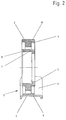
- the bearing comprises a dimensionally stable inner support ring 1 and a dimensionally stable outer support ring 2, which in this example consist of a metallic material and are supported on one another in a radially elastic manner by an intermediate ring 3 made of a rubber-elastic material.
- the intermediate ring 3 is formed by four web bodies which are evenly distributed in the circumferential direction and are each fixed to the support rings 1, 2 with inner and outer holding surfaces 5, 6.
- the outer support ring 2 is adhesively connected to a bearing holder 11, which can be penetrated by screws, for example, and connected to the body of a motor vehicle.
- the inner holding surfaces 5, which are arranged on the side of the web body 4 facing the inner support ring 2, and the outer holding surfaces 6, which are arranged on the side of the web body 4 facing the outer support ring 2, are inclined in the circumferential direction between the two support rings 1, 2 positioned.
- the central region of the circumferential extent of the inner and outer holding surfaces 5, 6 is in each case arranged relative to one another in such a way that an imaginary line 7 intersecting the central region of the circumferential extent of the holding surfaces 5, 6 has a radial plane 8 from which it extends is intersected, includes an angle A, which in this embodiment is approximately 45 °. Deviating angles, for example between 15 and 75 °, are also conceivable, the good properties of use being largely retained over a long period of use.
- the web bodies 4 In the region of their inner and outer holding surfaces 5, 6, the web bodies 4 have an extension that increases in the circumferential direction. This ensures a better fixing between the inner and the outer support body 1, 2.
- both the inner and the outer support ring 1, 2 are stiffened by metal inserts 10 which have openings penetrated by the elastic rubber material, the rubber material being designed to merge into one another on the side of the openings facing away from the web bodies 4.
- metal inserts 10 which have openings penetrated by the elastic rubber material, the rubber material being designed to merge into one another on the side of the openings facing away from the web bodies 4.
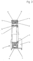
- FIG. 3 shows a bearing, similar to the bearing from FIGS. 1 and 2, with stop buffers 8, 9 being provided between the inner and the outer support ring 1, 2, which are formed in one piece with the web bodies 4.
- the stop buffers 8, 9 extend radially from the outer support ring 2 in the direction of the inner support ring 1 and can be brought into engagement with the counter surface in the event of extreme deflections of the two support bodies 1, 2 relative to one another.
Landscapes
- Engineering & Computer Science (AREA)
- General Engineering & Computer Science (AREA)
- Mechanical Engineering (AREA)
- Chemical & Material Sciences (AREA)
- Combustion & Propulsion (AREA)
- Transportation (AREA)
- Support Of The Bearing (AREA)
Applications Claiming Priority (2)
| Application Number | Priority Date | Filing Date | Title |
|---|---|---|---|
| DE4228170 | 1992-08-25 | ||
| DE4228170A DE4228170C2 (de) | 1992-08-25 | 1992-08-25 | Lager |
Publications (3)
| Publication Number | Publication Date |
|---|---|
| EP0585516A2 true EP0585516A2 (fr) | 1994-03-09 |
| EP0585516A3 EP0585516A3 (fr) | 1995-01-11 |
| EP0585516B1 EP0585516B1 (fr) | 1997-08-20 |
Family
ID=6466357
Family Applications (1)
| Application Number | Title | Priority Date | Filing Date |
|---|---|---|---|
| EP93102428A Expired - Lifetime EP0585516B1 (fr) | 1992-08-25 | 1993-02-17 | Palier |
Country Status (4)
| Country | Link |
|---|---|
| US (1) | US5547174A (fr) |
| EP (1) | EP0585516B1 (fr) |
| JP (1) | JP2541763B2 (fr) |
| DE (2) | DE4228170C2 (fr) |
Cited By (4)
| Publication number | Priority date | Publication date | Assignee | Title |
|---|---|---|---|---|
| WO1997016661A1 (fr) * | 1995-11-02 | 1997-05-09 | United Parts Fhs Automobil Systeme Gmbh | Dispositif pour commuter des boites de vitesses d'automobiles |
| US6428460B1 (en) * | 1998-02-19 | 2002-08-06 | Alfa Laval Ab | Support device for a centrifugal separator providing axial and radial support |
| DE102010004870A1 (de) * | 2010-01-18 | 2011-07-21 | Bosch Mahle Turbo Systems GmbH & Co. KG, 70376 | Drehlageranordnung |
| EP4311762A1 (fr) | 2022-07-29 | 2024-01-31 | AIRBUS HELICOPTERS DEUTSCHLAND GmbH | Porte d'aéronef avec un dispositif anti-vibration |
Families Citing this family (7)
| Publication number | Priority date | Publication date | Assignee | Title |
|---|---|---|---|---|
| DE19841882C1 (de) * | 1998-09-11 | 2000-03-02 | Freudenberg Carl Fa | Stützlager und Verfahren zu seiner Herstellung |
| FR2913078B1 (fr) * | 2007-02-27 | 2009-11-20 | Alcatel Lucent | Pivot traversant a lames. |
| FR2945848B1 (fr) * | 2009-05-19 | 2012-01-13 | Thales Sa | Pivot traversant a elements flexibles et engin spatial comportant un tel pivot |
| JP6113573B2 (ja) * | 2013-05-08 | 2017-04-12 | Nok株式会社 | センターベアリングサポート |
| DE102014218251B4 (de) * | 2014-09-11 | 2024-10-31 | BSH Hausgeräte GmbH | Haushaltsgerät |
| GB2557676A (en) * | 2016-12-15 | 2018-06-27 | Edwards Ltd | Bearing support for a vacuum pump |
| US12110936B2 (en) * | 2020-08-18 | 2024-10-08 | Illinois Tool Works Inc. | Silicone free rotational spring hinge dampener |
Family Cites Families (17)
| Publication number | Priority date | Publication date | Assignee | Title |
|---|---|---|---|---|
| DE8112477U1 (de) * | 1981-10-08 | Jörn GmbH, 7012 Fellbach | "Elastisches Gelenkwellen-Zwischenlager" | |
| US1633580A (en) * | 1924-06-14 | 1927-06-28 | Int Motor Co | Bearing |
| US2915306A (en) * | 1955-06-24 | 1959-12-01 | Albert F Hickman | Rubber torsion spring |
| GB979599A (en) * | 1962-11-27 | 1965-01-06 | Metalastik Ltd | Improvements in or relating to flexible mountings for shaft bearings |
| BE755351A (fr) * | 1969-09-10 | 1971-03-01 | Glaverbel | Procede et dispositif pour la fabrication de verre en feuille |
| DE2061625C3 (de) * | 1970-12-15 | 1980-03-06 | Daimler-Benz Ag, 7000 Stuttgart | Zwischenlager für die Gelenkwelle von Kraftfahrzeugen |
| JPS551314Y2 (fr) * | 1976-04-17 | 1980-01-16 | ||
| US4744677A (en) * | 1984-11-27 | 1988-05-17 | Tokai Rubber Industries, Ltd. | Bush assemblage |
| DE3509128C1 (de) * | 1985-03-14 | 1986-10-02 | Jean Walterscheid Gmbh, 5204 Lohmar | Lagerring |
| US4826145A (en) * | 1987-01-23 | 1989-05-02 | Dunlop Limited A British Company | Resilient torsion bearing |
| DE3724431A1 (de) * | 1987-07-23 | 1989-02-02 | Freudenberg Carl Fa | Huelsengummifeder |
| JPH0224124U (fr) * | 1988-08-01 | 1990-02-16 | ||
| DE3832543A1 (de) * | 1988-09-24 | 1990-04-05 | Vorwerk & Sohn | Lager fuer die elastische lagerung einer welle, insbesondere mittellager fuer die gelenkwelle eines fahrzeugantriebs |
| JPH0253543U (fr) * | 1988-10-08 | 1990-04-18 | ||
| DE3840176A1 (de) * | 1988-11-29 | 1990-05-31 | Freudenberg Carl Fa | Huelsengummifeder |
| FR2656393A1 (fr) * | 1989-12-27 | 1991-06-28 | Glaenzer Spicer Sa | Palier elastique support d'un arbre tournant. |
| US5209461A (en) * | 1990-07-23 | 1993-05-11 | Ltv Energy Products Company | Elastomeric torsional spring having tangential spokes with varying elastic response |
-
1992
- 1992-08-25 DE DE4228170A patent/DE4228170C2/de not_active Expired - Lifetime
-
1993
- 1993-02-17 DE DE59307155T patent/DE59307155D1/de not_active Expired - Fee Related
- 1993-02-17 EP EP93102428A patent/EP0585516B1/fr not_active Expired - Lifetime
- 1993-06-16 US US08/078,130 patent/US5547174A/en not_active Expired - Fee Related
- 1993-08-25 JP JP5210106A patent/JP2541763B2/ja not_active Expired - Lifetime
Cited By (5)
| Publication number | Priority date | Publication date | Assignee | Title |
|---|---|---|---|---|
| WO1997016661A1 (fr) * | 1995-11-02 | 1997-05-09 | United Parts Fhs Automobil Systeme Gmbh | Dispositif pour commuter des boites de vitesses d'automobiles |
| US6428460B1 (en) * | 1998-02-19 | 2002-08-06 | Alfa Laval Ab | Support device for a centrifugal separator providing axial and radial support |
| DE102010004870A1 (de) * | 2010-01-18 | 2011-07-21 | Bosch Mahle Turbo Systems GmbH & Co. KG, 70376 | Drehlageranordnung |
| EP4311762A1 (fr) | 2022-07-29 | 2024-01-31 | AIRBUS HELICOPTERS DEUTSCHLAND GmbH | Porte d'aéronef avec un dispositif anti-vibration |
| US12331558B2 (en) | 2022-07-29 | 2025-06-17 | Airbus Helicopters Deutschland GmbH | Aircraft door with an anti-vibration device |
Also Published As
| Publication number | Publication date |
|---|---|
| JPH06159358A (ja) | 1994-06-07 |
| DE4228170C2 (de) | 1995-06-29 |
| US5547174A (en) | 1996-08-20 |
| DE4228170A1 (de) | 1994-03-10 |
| JP2541763B2 (ja) | 1996-10-09 |
| EP0585516A3 (fr) | 1995-01-11 |
| DE59307155D1 (de) | 1997-09-25 |
| EP0585516B1 (fr) | 1997-08-20 |
Similar Documents
| Publication | Publication Date | Title |
|---|---|---|
| EP0462356B1 (fr) | Accouplement élastique rotatif | |
| DE2726676A1 (de) | Federelement, insbesondere zur elastischen lagerung von antriebs- oder sonstigen aggregaten in kraftfahrzeugen | |
| EP0585516B1 (fr) | Palier | |
| EP1233205A2 (fr) | Disposition de ressort | |
| DE69017292T2 (de) | Dynamischer Dämpfer. | |
| WO2010112006A1 (fr) | Articulation en élastomère | |
| EP1458596B1 (fr) | Fixation d'un systeme d'essuie-glace | |
| DE69008124T2 (de) | Schutzkappe für Gabelkopf. | |
| EP0585529B1 (fr) | Palier de support | |
| EP0472828A2 (fr) | Palier pour levier de changement de vitesse | |
| DE19728605A1 (de) | Stangen- oder Kolbendichtung | |
| DE2727725C2 (de) | Kupplungsscheibe mit Torsionsdämpfeinrichtung | |
| EP0149079B1 (fr) | Palier élastique rotatif à surface de glissement | |
| DE2507253A1 (de) | Anordnung mit einer gelagerten gestreckten welle | |
| DE10205264A1 (de) | Federbeinstützlager | |
| DE3314503C2 (de) | Schwingungstilger | |
| DE10223029B4 (de) | Verdrehungsfeste und verschiebungsfeste Vorrichtung eines Federungssystem | |
| DE3440104A1 (de) | Universalkupplung zur uebertragung einer drehbewegung und eines drehmoments zwischen zwei wellen | |
| EP1117485A1 (fr) | Dispositif de compensation de desequilibre pour centrifugeuses | |
| DE10354782B3 (de) | Torsionale Entkopplungselement für schwingbeanspruchte Rohrleitungen | |
| DE112022002329T5 (de) | Motor mit Untersetzungsgetriebe | |
| EP0985838B1 (fr) | Palier et méthode pour sa fabrication | |
| EP0585530B1 (fr) | Palier de support | |
| DE102010060198B4 (de) | Lager für einen Stabilisator eines Kraftfahrzeugs | |
| DE4040444C1 (en) | Cardan shaft bearing with two mutually surrounding supports - has axial fold at peripheral point(s) interrupted by cross-fold(s), as bellows deformation section |
Legal Events
| Date | Code | Title | Description |
|---|---|---|---|
| PUAI | Public reference made under article 153(3) epc to a published international application that has entered the european phase |
Free format text: ORIGINAL CODE: 0009012 |
|
| AK | Designated contracting states |
Kind code of ref document: A2 Designated state(s): DE FR GB IT SE |
|
| RAP3 | Party data changed (applicant data changed or rights of an application transferred) |
Owner name: FIRMA CARL FREUDENBERG |
|
| PUAL | Search report despatched |
Free format text: ORIGINAL CODE: 0009013 |
|
| RHK1 | Main classification (correction) |
Ipc: F16C 27/06 |
|
| AK | Designated contracting states |
Kind code of ref document: A3 Designated state(s): DE FR GB IT SE |
|
| 17P | Request for examination filed |
Effective date: 19941207 |
|
| 17Q | First examination report despatched |
Effective date: 19960123 |
|
| GRAG | Despatch of communication of intention to grant |
Free format text: ORIGINAL CODE: EPIDOS AGRA |
|
| GRAH | Despatch of communication of intention to grant a patent |
Free format text: ORIGINAL CODE: EPIDOS IGRA |
|
| GRAH | Despatch of communication of intention to grant a patent |
Free format text: ORIGINAL CODE: EPIDOS IGRA |
|
| GRAA | (expected) grant |
Free format text: ORIGINAL CODE: 0009210 |
|
| AK | Designated contracting states |
Kind code of ref document: B1 Designated state(s): DE FR GB IT SE |
|
| ITF | It: translation for a ep patent filed | ||
| REF | Corresponds to: |
Ref document number: 59307155 Country of ref document: DE Date of ref document: 19970925 |
|
| GBT | Gb: translation of ep patent filed (gb section 77(6)(a)/1977) |
Effective date: 19970904 |
|
| ET | Fr: translation filed | ||
| PLBE | No opposition filed within time limit |
Free format text: ORIGINAL CODE: 0009261 |
|
| STAA | Information on the status of an ep patent application or granted ep patent |
Free format text: STATUS: NO OPPOSITION FILED WITHIN TIME LIMIT |
|
| 26N | No opposition filed | ||
| REG | Reference to a national code |
Ref country code: GB Ref legal event code: IF02 |
|
| PGFP | Annual fee paid to national office [announced via postgrant information from national office to epo] |
Ref country code: GB Payment date: 20020204 Year of fee payment: 10 |
|
| PGFP | Annual fee paid to national office [announced via postgrant information from national office to epo] |
Ref country code: DE Payment date: 20020208 Year of fee payment: 10 |
|
| PGFP | Annual fee paid to national office [announced via postgrant information from national office to epo] |
Ref country code: FR Payment date: 20020221 Year of fee payment: 10 |
|
| PGFP | Annual fee paid to national office [announced via postgrant information from national office to epo] |
Ref country code: SE Payment date: 20020225 Year of fee payment: 10 |
|
| PG25 | Lapsed in a contracting state [announced via postgrant information from national office to epo] |
Ref country code: GB Free format text: LAPSE BECAUSE OF NON-PAYMENT OF DUE FEES Effective date: 20030217 |
|
| PG25 | Lapsed in a contracting state [announced via postgrant information from national office to epo] |
Ref country code: SE Free format text: LAPSE BECAUSE OF NON-PAYMENT OF DUE FEES Effective date: 20030218 |
|
| PG25 | Lapsed in a contracting state [announced via postgrant information from national office to epo] |
Ref country code: DE Free format text: LAPSE BECAUSE OF NON-PAYMENT OF DUE FEES Effective date: 20030902 |
|
| EUG | Se: european patent has lapsed | ||
| GBPC | Gb: european patent ceased through non-payment of renewal fee | ||
| PG25 | Lapsed in a contracting state [announced via postgrant information from national office to epo] |
Ref country code: FR Free format text: LAPSE BECAUSE OF NON-PAYMENT OF DUE FEES Effective date: 20031031 |
|
| REG | Reference to a national code |
Ref country code: FR Ref legal event code: ST |
|
| PG25 | Lapsed in a contracting state [announced via postgrant information from national office to epo] |
Ref country code: IT Free format text: LAPSE BECAUSE OF NON-PAYMENT OF DUE FEES;WARNING: LAPSES OF ITALIAN PATENTS WITH EFFECTIVE DATE BEFORE 2007 MAY HAVE OCCURRED AT ANY TIME BEFORE 2007. THE CORRECT EFFECTIVE DATE MAY BE DIFFERENT FROM THE ONE RECORDED. Effective date: 20050217 |