EP0585543B1 - Dispositif pour fixer des tuyaux au moyen d'un collier de fixation et d'un collier de support - Google Patents
Dispositif pour fixer des tuyaux au moyen d'un collier de fixation et d'un collier de support Download PDFInfo
- Publication number
- EP0585543B1 EP0585543B1 EP93108812A EP93108812A EP0585543B1 EP 0585543 B1 EP0585543 B1 EP 0585543B1 EP 93108812 A EP93108812 A EP 93108812A EP 93108812 A EP93108812 A EP 93108812A EP 0585543 B1 EP0585543 B1 EP 0585543B1
- Authority
- EP
- European Patent Office
- Prior art keywords
- pipe
- clip
- support
- clamp
- accordance
- Prior art date
- Legal status (The legal status is an assumption and is not a legal conclusion. Google has not performed a legal analysis and makes no representation as to the accuracy of the status listed.)
- Expired - Lifetime
Links
- 239000000463 material Substances 0.000 claims abstract description 6
- 229920001971 elastomer Polymers 0.000 claims description 33
- 239000002184 metal Substances 0.000 claims description 2
- 238000010276 construction Methods 0.000 claims 1
- 239000000806 elastomer Substances 0.000 description 27
- 238000009413 insulation Methods 0.000 description 7
- 239000010865 sewage Substances 0.000 description 6
- 230000005540 biological transmission Effects 0.000 description 2
- 230000006835 compression Effects 0.000 description 2
- 238000007906 compression Methods 0.000 description 2
- 238000004519 manufacturing process Methods 0.000 description 2
- 230000007704 transition Effects 0.000 description 2
- 238000006073 displacement reaction Methods 0.000 description 1
- 230000000694 effects Effects 0.000 description 1
- 239000013013 elastic material Substances 0.000 description 1
- 230000005484 gravity Effects 0.000 description 1
- 239000011343 solid material Substances 0.000 description 1
- 125000006850 spacer group Chemical group 0.000 description 1
- 239000002351 wastewater Substances 0.000 description 1
Images

Classifications
-
- E—FIXED CONSTRUCTIONS
- E04—BUILDING
- E04D—ROOF COVERINGS; SKY-LIGHTS; GUTTERS; ROOF-WORKING TOOLS
- E04D13/00—Special arrangements or devices in connection with roof coverings; Protection against birds; Roof drainage ; Sky-lights
- E04D13/04—Roof drainage; Drainage fittings in flat roofs, balconies or the like
- E04D13/08—Down pipes; Special clamping means therefor
-
- F—MECHANICAL ENGINEERING; LIGHTING; HEATING; WEAPONS; BLASTING
- F16—ENGINEERING ELEMENTS AND UNITS; GENERAL MEASURES FOR PRODUCING AND MAINTAINING EFFECTIVE FUNCTIONING OF MACHINES OR INSTALLATIONS; THERMAL INSULATION IN GENERAL
- F16L—PIPES; JOINTS OR FITTINGS FOR PIPES; SUPPORTS FOR PIPES, CABLES OR PROTECTIVE TUBING; MEANS FOR THERMAL INSULATION IN GENERAL
- F16L3/00—Supports for pipes, cables or protective tubing, e.g. hangers, holders, clamps, cleats, clips, brackets
- F16L3/08—Supports for pipes, cables or protective tubing, e.g. hangers, holders, clamps, cleats, clips, brackets substantially surrounding the pipe, cable or protective tubing
- F16L3/12—Supports for pipes, cables or protective tubing, e.g. hangers, holders, clamps, cleats, clips, brackets substantially surrounding the pipe, cable or protective tubing comprising a member substantially surrounding the pipe, cable or protective tubing
-
- F—MECHANICAL ENGINEERING; LIGHTING; HEATING; WEAPONS; BLASTING
- F16—ENGINEERING ELEMENTS AND UNITS; GENERAL MEASURES FOR PRODUCING AND MAINTAINING EFFECTIVE FUNCTIONING OF MACHINES OR INSTALLATIONS; THERMAL INSULATION IN GENERAL
- F16L—PIPES; JOINTS OR FITTINGS FOR PIPES; SUPPORTS FOR PIPES, CABLES OR PROTECTIVE TUBING; MEANS FOR THERMAL INSULATION IN GENERAL
- F16L55/00—Devices or appurtenances for use in, or in connection with, pipes or pipe systems
- F16L55/02—Energy absorbers; Noise absorbers
- F16L55/033—Noise absorbers
- F16L55/035—Noise absorbers in the form of specially adapted hangers or supports
-
- E—FIXED CONSTRUCTIONS
- E04—BUILDING
- E04D—ROOF COVERINGS; SKY-LIGHTS; GUTTERS; ROOF-WORKING TOOLS
- E04D13/00—Special arrangements or devices in connection with roof coverings; Protection against birds; Roof drainage ; Sky-lights
- E04D13/04—Roof drainage; Drainage fittings in flat roofs, balconies or the like
- E04D13/08—Down pipes; Special clamping means therefor
- E04D2013/084—Means for fixing down pipes to structure
Definitions
- the present invention relates to a pipe fastening device with a fixing clamp that firmly encompasses a pipe and a support clamp surrounding the pipe with a predetermined tolerance, which can be fastened to an object, in particular a wall, and with its one end face designed as a support surface against an axially opposite one designed as a supporting surface
- the end face of the fixing clamp is pressed on and thereby carries the pipe via the fixing clamp, the material having sound-absorbing properties at least in the area of the supporting and / or supporting surface and preferably being rubber-elastic.
- a pipe fastening device of the type described is described in the older EP-A-0 582 354.
- This application which according to Avt. 54 (3) EPC for all designated contracting states with the exception of Luxembourg, the priority-based application is NL-A-9201410 (05.08.92).
- the fixing clamp which consists of a metallic clamp element and an elastic element located between this clamp element and the pipe wall, is clamped to the pipe.
- the elastic element has on the side of the tube wall a plurality of ribs running in the circumferential direction, the radial height of which corresponds to at least half of the radial extent of the elastomeric element.
- the support clamp also consists of a metallic clamp element and an elastomeric element provided between this clamp element and the tube wall, the radial extension of the support clamp corresponding approximately to the radial extension of the fixing clamp.
- the support clamp is not connected to the pipe by a test clamp fit, but is relatively loosely attached, i. H. not placed close enough around the pipe to prevent the pipe from sliding down through the clamp under the influence of gravity. There is hardly any contact between the pipe-side ribs of the support clamp and the pipe.
- Pipe fastening devices of this type are used, for example, for fastening sewage pipes to house walls in order to achieve structure-borne noise decoupling between the sewage pipe and the wall.
- a pipe fastening device without soundproofing properties
- the noises that occur when the sewage pipe flows through are very well transmitted to the wall via the fixed connection, and can therefore be perceived as disruptive throughout the building.
- the support bracket has an inner diameter that is larger than the outer diameter of the tube, so that the tube and the support bracket are not in contact with each other.
- the areas of the support and / or fixing clamp which are connected to one another are made of materials with sound-absorbing properties, for example rubber, so that the transmission of the noise from the pipe to the support clamp is damped.
- the support surface of the support clamp is usually designed as support lips surrounding the tube, since this achieves good acoustic decoupling between the fixing clamp and the support clamp.
- a concentric arrangement of the two clamps is necessary for the sound insulation to function properly. If the pipe and thus also the fixing clamp is shifted in relation to the support clamp, as can already happen during assembly or in the course of time due to external influences, this has the consequence that the outer edge of the fixing clamp on one side of the pipe over the Support clamp protrudes radially, while on the other side of the tube it only rests on a part of the support clamp, for example only on a support lip.
- the object of the invention is to provide a pipe fastening device in which perfect sound insulation is ensured even when the support clamp is not concentrically attached to the fixing clamp.
- the fixing clamp and / or the support clamp each consist of a rigid clamp element and an elastomer element which rests on the end face of the adjacent clamp element.
- Both facing end faces of the clamp elements are preferably formed from an elastomer element, since particularly good sound insulation is thereby achieved. In certain cases, however, it may also be sufficient if only the end face of a clamp is designed as an elastomer element, so that it rests on the rigid end face of the adjacent clamp element.
- the inside of at least one of the rigid clamp elements lies essentially completely against the associated elastomer element.
- the rigid clamp element of the fixing clamp has no direct contact with the pipe, so that even a partial soundproofing takes place due to the compressed elastomer element of the fixing clamp.
- the elastomer element attached to the inside prevents the rigid clamp element from coming into direct contact with the pipe when the support clamp is displaced radially, which leads to a significant increase in those transmitted to the wall would cause noises.
- At least one of the elastomer elements preferably consists of rubber, in particular of profiled rubber.
- At least one of the rigid clamp elements is preferably made of metal. This enables simple production with simultaneous pipe stability.
- At least one of the rigid clamp elements preferably has an essentially flat bar-shaped profile. This commercially available embodiment enables a particularly inexpensive production of a pipe fastening device designed according to the invention.
- At least one of the rigid clamp elements has an annular flange which extends radially outward from the end face facing the other clamp element and is axially opposite the other clamp element.
- the opposite support and support surfaces can be made particularly wide and at the same time particularly stable. This ensures perfect sound insulation even when the support clamp is displaced particularly far from the pipe.
- the advantage of the invention is that even with a wide displacement of the support clamp relative to the tube and thus relative to the fixing clamp, the support surface lies completely against the support surface over its entire circumference. This ensures. that the area of the support bracket forming the support surface is always evenly loaded by the weight of the tube and thus no deformations or unusual compression of the rubber-elastic material can occur. In this way, the desired sound insulation between the pipe and the wall is provided with a perfect bracket both with concentric and non-concentric attachment of the support clamp.
- the pipe fastening device 13 consists of a fixing clamp 17 and a support clamp 19 which is fastened to the wall 15 via a holder 21.
- the fixing clamp 17 and the support clamp 19 each consist of a rigid clamp element 23, 25, which are designed as tension clamps, and of elastomer elements 27, 29, which are encompassed by the rigid clamp elements 23, 25.
- the elastomer element 27 is so tightly clamped around the tube 11 by the rigid clamp element 23 via a screw 31 that, due to the friction between the tube 11 and the elastomer element 27, no axial movement of the tube relative to the fixing clamp 17 is possible.
- the lower face of the elastomer element 27 lies on the upper face of the elastomer element 29.
- the elastomer element 29 is not pressed against the tube 11 by the rigid clamp element 25, but is removed over its entire circumference from the tube 11 by a tolerance 33 (FIG. 2).
- a spacer 35 is arranged between the two free ends of the rigid clamp element 25, so that when the rigid clamp element 25 is braced by a screw 37, it cannot fall below a certain minimum inner diameter of the support clamp 19, which is larger than the outer diameter of the tube 11.
- Noises which are generated for example by waste water flowing through the pipe 11, propagate, slightly reduced by the compressed elastomer element 27, to the transition point 39 between the elastomer 27 and the elastoiner 29.
- the lower end face of the elastomer element 27 forms an airfoil 41 (FIG. 2) which is essentially uncompressed and therefore has sound-absorbing properties.
- the upper end face of the elastomer 29 forms a support surface 43 (FIG. 2) which, like the entire elastomer element 29, consists of uncompressed material and therefore has particularly good sound-insulating properties.
- the sound waves conducted into the elastomer element 27 are only partly passed on via the transition point 39 into the elastomer element 29, where they are then largely absorbed. In this way, good sound insulation is created between the tube 11 and the wall 15.
- FIG. 2 a shows a cross section through a pipe fastening device according to FIG. 1, in which, as in FIG. 1, the support clamp 19 is aligned concentrically with the fixing clamp 17 and thus the pipe 11.
- Fig. 2b the support bracket 19 is shown with respect to the tube 11 and the fixing bracket 17 by the tolerance 33 maximally shifted to the left.
- the profile 49 comes into contact with the pipe 11.
- the support bracket 19 is located so far from the tube 11 that only one support lip 45 'rests on the underside of the fixing bracket 17.
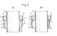
- Fig. 3 shows a cross section through a pipe fastening device designed according to the invention.
- the support bracket 19 is again arranged concentrically to the fixing bracket 17 and the tube 11.
- the elastomer element 27 is so wide that the support surface 41 extends radially beyond the outer edge of the support surface 43. Since the area of the elastomer element 27 is compressed between the rigid clamp element 23 and the tube 11, it has a sufficiently high strength to be able to be used as a supporting element.
Landscapes
- Engineering & Computer Science (AREA)
- General Engineering & Computer Science (AREA)
- Mechanical Engineering (AREA)
- Architecture (AREA)
- Civil Engineering (AREA)
- Structural Engineering (AREA)
- Supports For Pipes And Cables (AREA)
- Pipe Accessories (AREA)
- Clamps And Clips (AREA)
Claims (8)
- Dispositif (13) pour fixer des tuyaux au moyen d'un collier de fixation (17), qui enserre de façon fixe un tuyau (11), et d'un collier de support (19), qui entoure le tuyau (11) avec un jeu prédéfini (33), que l'on peut fixer sur un objet, en particulier sur une cloison (15) et que l'on peut presser par sa face frontale constituée sous la forme d'une surface d'appui (43) contre une face frontale du collier de fixation (17), constituée en tant que surface portante (41) se trouvant axialement en regard, et qui de cette façon porte le tuyau (11) au moyen du collier de fixation (17), la matière ayant, au moins dans la zone de la surface d'appui et/ou de la surface portante (43, 41), des propriétés qui amortissent les sons et qui est de préférence élastique comme du caoutchouc, et dans lequel la surface portante (41) s'étend, quand le collier de fixation (17), le collier de support (19) et le tuyau (11) sont orientés coaxialement, sensiblement sur tout son pourtour sur la surface d'appui (43) suffisamment loin dans le sens radial pour que la surface d'appui (43), quand le collier de support (19) est décalé radialement par rapport au tuyau (11) de la longueur du jeu (33), repose sur tout son pourtour encore sensiblement complètement sur la surface portante (41), dispositif (13) pour fixer des tuyaux, dans lequel, quand il est monté, le diamètre extérieur d'un élément de collier (23) raide, correspondant au collier de fixation (17), est plus grand que le diamètre extérieur d'un élément de collier (25) raide, correespondant au collier de support (19).
- Dispositif (13) pour fixer des tuyaux, selon la revendication 1, caractérisé en ce que le collier de fixation (17) et/ou le collier de support (19) consistent respectivement en le même élément raide de collier (23, 25) et un élément élastomère (27, 29), qui repose sur la face frontale de l'élément de collier voisin (17, 19).
- Dispositif (13) pour fixer des tuyaux, selon la revendication 2, caractérisé en ce que la face intérieure d'au moins l'un des éléments raides de collier (23, 25) repose sensiblement complètement sur l'élément élastomère (27, 29) correspondant.
- Dispositif (13) pour fixer des tuyaux, selon une ou plusieurs des revendications 2 et 3, caractérisé en ce qu'au moins l'un des éléments élastomères (27, 29) est réalisé de préférence en caoutchouc, de préférence en caoutchouc profilé.
- Dispositif (13) pour fixer des tuyaux, selon une ou plusieurs des revendications 2 à 4, caractérisé en ce qu'au moins l'un des éléments élastomères (27, 29) est constitué en plusieurs parties.
- Dispositif (13) pour fixer des tuyaux, selon une ou plusieurs des revendications 2 à 5, caractérisé en ce qu'au moins l'un des éléments raides de collier (23, 25) est fabriqué en métal.
- Dispositif (13) pour fixer des tuyaux, selon une ou plusieurs des revendications 2 à 6, caractérisé en ce qu'au moins l'un des éléments raides de collier (23, 25) présente un profil qui a sensiblement la forme d'une barre plate.
- Dispositif (13) pour fixer des tuyaux, selon l'une des revendications 1 à 7, caractérisé en ce que l'élément élastomère associé au collier de support (19) est pourvu, sur sa face tournée vers le tuyau (11) , de nervures et en ce que l'élément élastomère (27), associé au collier de fixation (17), repose complètement sur le tuyau (11).
Applications Claiming Priority (2)
| Application Number | Priority Date | Filing Date | Title |
|---|---|---|---|
| DE4228961 | 1992-08-31 | ||
| DE4228961A DE4228961C2 (de) | 1992-08-31 | 1992-08-31 | Rohrbefestigungsvorrichtung mit einer Fixier- und einer Stützschelle |
Publications (2)
| Publication Number | Publication Date |
|---|---|
| EP0585543A1 EP0585543A1 (fr) | 1994-03-09 |
| EP0585543B1 true EP0585543B1 (fr) | 1996-08-21 |
Family
ID=6466850
Family Applications (1)
| Application Number | Title | Priority Date | Filing Date |
|---|---|---|---|
| EP93108812A Expired - Lifetime EP0585543B1 (fr) | 1992-08-31 | 1993-06-01 | Dispositif pour fixer des tuyaux au moyen d'un collier de fixation et d'un collier de support |
Country Status (3)
| Country | Link |
|---|---|
| EP (1) | EP0585543B1 (fr) |
| AT (1) | ATE141678T1 (fr) |
| DE (2) | DE4228961C2 (fr) |
Families Citing this family (12)
| Publication number | Priority date | Publication date | Assignee | Title |
|---|---|---|---|---|
| US5647564A (en) * | 1992-08-05 | 1997-07-15 | J. Van Walraven B.V. | Method for fastening a pipe in a vertical position to a wall |
| DE9414600U1 (de) * | 1994-07-20 | 1994-11-10 | J. Van Walraven B.V., Mijdrecht | Anordnung zur schwingungsdämpfenden Befestigung eines Leitungsrohrs an einer tragenden Wand |
| DE4433640A1 (de) * | 1994-09-21 | 1996-03-28 | Sina Befestigungssysteme Gmbh | Rohrschelle |
| NL1004919C2 (nl) * | 1996-12-31 | 1998-07-01 | Walraven J Van Bv | Inrichting voor trilling-dempende bevestiging van een buisleiding aan een dragende wand. |
| NL1005123C2 (nl) * | 1997-01-29 | 1998-07-30 | Walraven J Van Bv | Buisklemsamenstel voor het trilling-dempend bevestigen van een buis aan een wand. |
| DE10014050C1 (de) * | 2000-03-23 | 2001-10-31 | Rehau Ag & Co | Vorrichtung zur Befestigung von Rohren |
| FR2949250B1 (fr) | 2009-08-24 | 2012-01-06 | Aliaxis R & D Sas | Pont amortissant |
| DE102014215394B3 (de) * | 2014-08-05 | 2015-05-21 | Poloplast Gmbh & Co. Kg | Hochschalldämmende Rohrbefestigungsvorrichtung |
| DE202014008983U1 (de) | 2014-11-12 | 2014-12-09 | Poloplast Gmbh & Co Kg | Hochschalldämmende Rohrbefestigungsvorrichtung |
| EP2982895B1 (fr) | 2014-08-05 | 2017-08-09 | Poloplast GmbH & Co. KG | Dispositif de fixation de tube insonorisant |
| DK3196527T3 (da) * | 2016-01-19 | 2020-05-11 | Geberit Int Ag | Støtteanordning |
| CN112833257B (zh) * | 2021-01-26 | 2022-06-07 | 东南大学 | 一种柔性建筑横向管道支吊架 |
Citations (2)
| Publication number | Priority date | Publication date | Assignee | Title |
|---|---|---|---|---|
| EP0582354A1 (fr) * | 1992-08-05 | 1994-02-09 | J. van Walraven B.V. | Méthode pour la fixation d'un conduit en position verticale sur un mur |
| NL9201410A (nl) * | 1992-08-05 | 1994-03-01 | Walraven J Van Bv | Voering voor een pijpbevestigingsbeugel. |
Family Cites Families (3)
| Publication number | Priority date | Publication date | Assignee | Title |
|---|---|---|---|---|
| US3856245A (en) * | 1973-03-14 | 1974-12-24 | Viking Industries | Pipe mounting clamp |
| DE8910177U1 (de) * | 1989-08-25 | 1989-12-28 | Poppe & Co Gießener Gummiwarenfabrik GmbH & Co KG, 6300 Gießen | Einlage für eine Rohrschelle |
| DE4107885A1 (de) * | 1991-03-12 | 1992-09-17 | Missel Gmbh & Co E | Rohrschelle, insbesondere fuer installationsrohre, fallrohre u. dgl. |
-
1992
- 1992-08-31 DE DE4228961A patent/DE4228961C2/de not_active Expired - Fee Related
-
1993
- 1993-06-01 DE DE59303490T patent/DE59303490D1/de not_active Expired - Fee Related
- 1993-06-01 EP EP93108812A patent/EP0585543B1/fr not_active Expired - Lifetime
- 1993-06-01 AT AT93108812T patent/ATE141678T1/de not_active IP Right Cessation
Patent Citations (2)
| Publication number | Priority date | Publication date | Assignee | Title |
|---|---|---|---|---|
| EP0582354A1 (fr) * | 1992-08-05 | 1994-02-09 | J. van Walraven B.V. | Méthode pour la fixation d'un conduit en position verticale sur un mur |
| NL9201410A (nl) * | 1992-08-05 | 1994-03-01 | Walraven J Van Bv | Voering voor een pijpbevestigingsbeugel. |
Also Published As
| Publication number | Publication date |
|---|---|
| EP0585543A1 (fr) | 1994-03-09 |
| DE59303490D1 (de) | 1996-09-26 |
| ATE141678T1 (de) | 1996-09-15 |
| DE4228961A1 (de) | 1994-03-03 |
| DE4228961C2 (de) | 1995-01-26 |
Similar Documents
| Publication | Publication Date | Title |
|---|---|---|
| DE69411935T2 (de) | Schlauchschelle | |
| EP0992717B1 (fr) | Anneau d'étanchéité plat | |
| DE3216938C2 (de) | Rohrverbindung | |
| EP2584240B1 (fr) | Bride de fixation avec élément d'étanchéité | |
| CH664612A5 (de) | Steckkupplung zum verbinden der enden zweier rohre. | |
| EP0585543A1 (fr) | Dispositif pour fixer des tuyaux au moyen d'un collier de fixation et d'un collier de support | |
| DD298542A5 (de) | Rohrkupplung | |
| EP0060567A1 (fr) | Support insonorisant | |
| DE2714963B2 (de) | Elastisches Rohrverbindungsstück | |
| DE2911575A1 (de) | Zugfeste rohrkupplung | |
| EP0139823B1 (fr) | Soufflet compensateur en métal isolé phoniquement | |
| DE3612420C2 (fr) | ||
| EP2982895B1 (fr) | Dispositif de fixation de tube insonorisant | |
| EP1586789A1 (fr) | Support élastique pour une cabine de véhicule | |
| DE102014215394B3 (de) | Hochschalldämmende Rohrbefestigungsvorrichtung | |
| EP0863334A2 (fr) | Soufflet | |
| DE102004047173B4 (de) | Elastisches Motorlager zur Lagerung einer Brennkraftmaschine in einem Kraftfahrzeug und Verfahren zur Dimensionierung eines solchen Lagers | |
| DE102005047955B3 (de) | Vorrichtung zur Abdichtung zwischen einem Lenkgetriebegehäuse und einem Stirnwandblech | |
| DE10014050C1 (de) | Vorrichtung zur Befestigung von Rohren | |
| EP0742404A1 (fr) | Collier de serrage avec chemise élastique | |
| DE102012005943A1 (de) | Vorrichtung zum Verbinden von zwei Rundkörpern mit unterschiedlichen Außendurchmessern | |
| EP1500853A1 (fr) | Joint d'étanchéité à diamètre interne variable | |
| DE202014008983U1 (de) | Hochschalldämmende Rohrbefestigungsvorrichtung | |
| DE69412438T2 (de) | Mechanismus zum Befestigen einer Bildröhre in ihrem Gehäuse | |
| EP0498322B1 (fr) | Dispositif d'étanchéité pour l'assemblage de deux extrémités à tuyaux cylindriques et lisses |
Legal Events
| Date | Code | Title | Description |
|---|---|---|---|
| PUAI | Public reference made under article 153(3) epc to a published international application that has entered the european phase |
Free format text: ORIGINAL CODE: 0009012 |
|
| AK | Designated contracting states |
Kind code of ref document: A1 Designated state(s): AT BE CH DE FR IT LI LU NL |
|
| 17P | Request for examination filed |
Effective date: 19940421 |
|
| 17Q | First examination report despatched |
Effective date: 19950309 |
|
| GRAG | Despatch of communication of intention to grant |
Free format text: ORIGINAL CODE: EPIDOS AGRA |
|
| GRAH | Despatch of communication of intention to grant a patent |
Free format text: ORIGINAL CODE: EPIDOS IGRA |
|
| GRAH | Despatch of communication of intention to grant a patent |
Free format text: ORIGINAL CODE: EPIDOS IGRA |
|
| GRAA | (expected) grant |
Free format text: ORIGINAL CODE: 0009210 |
|
| ITF | It: translation for a ep patent filed | ||
| AK | Designated contracting states |
Kind code of ref document: B1 Designated state(s): AT BE CH DE FR IT LI LU NL |
|
| REF | Corresponds to: |
Ref document number: 141678 Country of ref document: AT Date of ref document: 19960915 Kind code of ref document: T |
|
| REF | Corresponds to: |
Ref document number: 59303490 Country of ref document: DE Date of ref document: 19960926 |
|
| ET | Fr: translation filed | ||
| PLBE | No opposition filed within time limit |
Free format text: ORIGINAL CODE: 0009261 |
|
| STAA | Information on the status of an ep patent application or granted ep patent |
Free format text: STATUS: NO OPPOSITION FILED WITHIN TIME LIMIT |
|
| 26N | No opposition filed | ||
| PGFP | Annual fee paid to national office [announced via postgrant information from national office to epo] |
Ref country code: DE Payment date: 19990726 Year of fee payment: 7 |
|
| PG25 | Lapsed in a contracting state [announced via postgrant information from national office to epo] |
Ref country code: DE Free format text: LAPSE BECAUSE OF NON-PAYMENT OF DUE FEES Effective date: 20010403 |
|
| PGFP | Annual fee paid to national office [announced via postgrant information from national office to epo] |
Ref country code: LU Payment date: 20020711 Year of fee payment: 10 |
|
| PG25 | Lapsed in a contracting state [announced via postgrant information from national office to epo] |
Ref country code: LU Free format text: LAPSE BECAUSE OF NON-PAYMENT OF DUE FEES Effective date: 20030601 |
|
| PGFP | Annual fee paid to national office [announced via postgrant information from national office to epo] |
Ref country code: AT Payment date: 20040611 Year of fee payment: 12 |
|
| PGFP | Annual fee paid to national office [announced via postgrant information from national office to epo] |
Ref country code: NL Payment date: 20040617 Year of fee payment: 12 |
|
| PGFP | Annual fee paid to national office [announced via postgrant information from national office to epo] |
Ref country code: FR Payment date: 20040618 Year of fee payment: 12 |
|
| PGFP | Annual fee paid to national office [announced via postgrant information from national office to epo] |
Ref country code: CH Payment date: 20040623 Year of fee payment: 12 Ref country code: BE Payment date: 20040623 Year of fee payment: 12 |
|
| PG25 | Lapsed in a contracting state [announced via postgrant information from national office to epo] |
Ref country code: IT Free format text: LAPSE BECAUSE OF NON-PAYMENT OF DUE FEES;WARNING: LAPSES OF ITALIAN PATENTS WITH EFFECTIVE DATE BEFORE 2007 MAY HAVE OCCURRED AT ANY TIME BEFORE 2007. THE CORRECT EFFECTIVE DATE MAY BE DIFFERENT FROM THE ONE RECORDED. Effective date: 20050601 Ref country code: AT Free format text: LAPSE BECAUSE OF NON-PAYMENT OF DUE FEES Effective date: 20050601 |
|
| PG25 | Lapsed in a contracting state [announced via postgrant information from national office to epo] |
Ref country code: LI Free format text: LAPSE BECAUSE OF NON-PAYMENT OF DUE FEES Effective date: 20050630 Ref country code: CH Free format text: LAPSE BECAUSE OF NON-PAYMENT OF DUE FEES Effective date: 20050630 Ref country code: BE Free format text: LAPSE BECAUSE OF NON-PAYMENT OF DUE FEES Effective date: 20050630 |
|
| PG25 | Lapsed in a contracting state [announced via postgrant information from national office to epo] |
Ref country code: NL Free format text: LAPSE BECAUSE OF NON-PAYMENT OF DUE FEES Effective date: 20060101 |
|
| REG | Reference to a national code |
Ref country code: CH Ref legal event code: PL |
|
| PG25 | Lapsed in a contracting state [announced via postgrant information from national office to epo] |
Ref country code: FR Free format text: LAPSE BECAUSE OF NON-PAYMENT OF DUE FEES Effective date: 20060228 |
|
| NLV4 | Nl: lapsed or anulled due to non-payment of the annual fee |
Effective date: 20060101 |
|
| REG | Reference to a national code |
Ref country code: FR Ref legal event code: ST Effective date: 20060228 |
|
| BERE | Be: lapsed |
Owner name: E. *MISSEL G.M.B.H. & CO. Effective date: 20050630 |