EP0585562B1 - Verbinder - Google Patents
Verbinder Download PDFInfo
- Publication number
- EP0585562B1 EP0585562B1 EP93110807A EP93110807A EP0585562B1 EP 0585562 B1 EP0585562 B1 EP 0585562B1 EP 93110807 A EP93110807 A EP 93110807A EP 93110807 A EP93110807 A EP 93110807A EP 0585562 B1 EP0585562 B1 EP 0585562B1
- Authority
- EP
- European Patent Office
- Prior art keywords
- connector
- housing
- stopper
- rubber ring
- connector housing
- Prior art date
- Legal status (The legal status is an assumption and is not a legal conclusion. Google has not performed a legal analysis and makes no representation as to the accuracy of the status listed.)
- Expired - Lifetime
Links
- 230000002093 peripheral effect Effects 0.000 claims description 15
- 239000002184 metal Substances 0.000 description 6
- 230000015556 catabolic process Effects 0.000 description 4
- 238000010276 construction Methods 0.000 description 2
- 239000000428 dust Substances 0.000 description 2
- 238000012986 modification Methods 0.000 description 2
- 230000004048 modification Effects 0.000 description 2
- 239000011810 insulating material Substances 0.000 description 1
- 238000009413 insulation Methods 0.000 description 1
- 230000000149 penetrating effect Effects 0.000 description 1
- 238000007789 sealing Methods 0.000 description 1
- 229920003002 synthetic resin Polymers 0.000 description 1
- 239000000057 synthetic resin Substances 0.000 description 1
Images


Classifications
-
- H—ELECTRICITY
- H01—ELECTRIC ELEMENTS
- H01R—ELECTRICALLY-CONDUCTIVE CONNECTIONS; STRUCTURAL ASSOCIATIONS OF A PLURALITY OF MUTUALLY-INSULATED ELECTRICAL CONNECTING ELEMENTS; COUPLING DEVICES; CURRENT COLLECTORS
- H01R13/00—Details of coupling devices of the kinds covered by groups H01R12/70 or H01R24/00 - H01R33/00
- H01R13/46—Bases; Cases
- H01R13/52—Dustproof, splashproof, drip-proof, waterproof, or flameproof cases
- H01R13/5219—Sealing means between coupling parts, e.g. interfacial seal
Definitions
- the present invention relates to a connector and more particularly, the connector comprising a waterproof rubber ring provided on the inner surface of an engaging hole formed in a housing of a female connector so as to seal the space between the inner surface of the engaging hole and he outer surface of a housing of a male connector inserted into the housing of the female connector, in which a plurality of stopper convex portions is formed on the outer surface of the waterproof rubber ring.
- a waterproof rubber ring 2 is installed in an engaging hole la, formed on a housing 1 of the female connector, for inserting the male connector (not shown) thereinto.
- the waterproof rubber ring 2 is provided to seal the space between the inner peripheral surface of the engaging hole la and the peripheral surface of the male connector.
- a pair of stopper projections 2a and 2a is formed on the peripheral surface of the rubber ring 2.
- a pair of stopper openings 1b and 1b is formed on the peripheral surface of the connector housing 1. Each of the stopper projections 2a and 2a engages each of the stopper openings 1b and 1b. In this manner, the rubber ring 2 is fixed to the connector housing 1.
- the stopper openings 1b and 1b penetrate through the wall of the connector housing 1. There is a short insulation distance between a terminal (not shown) inserted into a terminal accommodating hole 1c (not shown) as well as a connector (not shown) of the male connector and the peripheral surface of the connector housing 1. Consequently, if a high voltage is applied from the terminals to a metal component adjacent to the peripheral surface of the connector housing 1, electric current flows from the terminals to the metal component via the stopper openings 1b and 1b. As a result, a breakdown occurs in the connector housing 1.
- a connector comprising a waterproof rubber ring provided on the inner surface of an engaging hole formed in a housing of a female connector so as to seal the space between the inner surface of the engaging hole and the outer surface of a housing of a male connector inserted into the housing of the female connector.
- a plurality of stopper convex portions is formed on the outer surface of the waterproof rubber ring.
- a plurality of stopper concave portions which is engaged by each of the stopper convex portions is formed on the inner surface of the housing of the female connector.
- a plurality of stopper concave portions formed on the inner surface of the housing of the female connector is engaged by each of the stopper convex portions formed on the outer surface of the waterproof rubber ring.
- a part of the peripheral wall between the bottom surface of each stopper concave portion and the outer surface of the housing of the female connector maintains insulating performance effectively. Accordingly, there is a comparatively long insulating distance between terminals accommodated in the accommodating chamber of the housing of the female connector and a metal component adjacent to the outer surface of the housing of the female connector. Thus, even though a high voltage is applied from the terminals to the metal component, leakage is unlikely to occur. Thus, no breakdown occurs in the housing of the female connector.
- the stopper convex portions of the rubber ring are not exposed to dust or rain. Accordingly, the housing of the female connector has a preferable insulating performance and thus the rubber ring is durable.
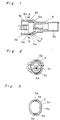
- an engaging hole 5a and an accommodating chamber 5b are formed in a cylindrical connector housing 5 of a female connector comprising an insulating material made of synthetic resin or the like.
- a male connector (not shown) is inserted into the connector housing 5 through the engaging hole 5a.
- a terminal is accommodated in the accommodating chamber 5b.
- a pair of stopper concave portions 5d and 5d is formed on the inner peripheral surface of the engaging hole 5a of the connector housing 5 as shown in Figs. 2 and 3.
- the line connecting the stopper concave portions 5d and 5d with each other divides the circumference of the engaging hole 5a equally as shown in Figs. 2 and 3.
- the stopper concave portions 5d and 5d do not penetrate through the peripheral wall 5c of the connector housing 5, but are formed in a certain distance from the inner surface of the connector housing 5 toward the outer surface thereof.
- a waterproof rubber ring 6 engages the inner peripheral surface of the connector housing 5, and the inner surface thereof engages the outer surface of the connector housing of the male connector inserted into the female connector.
- a pair of stopper convex portions 6a and 6a and contact projections 6b and 6b are formed on the outer surface of the rubber ring 6.
- Each of the stopper convex portions 6a and 6a inserted into the connector housing 5 engages each of the stopper concave portions 5d and 5d radially.
- the rubber ring 6 is inserted into the engaging hole 5a of the connector housing 5, and each of the stopper convex portions 6a and 6a of the rubber ring 6 is inserted into each of the stopper concave portions 5d and 5d so that the former is engaged by the latter. In this manner, the rubber ring 6 is fixed to the connector housing 5 at a predetermined position thereof.
- the male connector is inserted into the engaging hole 5a of the connector housing 5 so as to connect the terminals of both connectors with each other.
- the outer surface of the male connector closely contacts the inner surface of the rubber ring 6 in engagement therewith, and the outer surface of the rubber ring 6 closely contacts the inner surface of the engaging hole 5a of the connector housing 5 in engagement therewith, thus watertightly sealing the space between the male connector and the rubber ring 6 and the space between the rubber ring 6 and the connector housing 5.
- the stopper convex portions 6a and 6a of the rubber ring 6 is covered with the peripheral wall 5c of the connector housing 5, the stopper convex portions 6a and 6a are not exposed to dust or rain.
- the connector housing 5 has a preferable insulating performance and thus the rubber ring 6 is durable.
Landscapes
- Connector Housings Or Holding Contact Members (AREA)
Claims (2)
- Verbinder mit einem wasserdichten Gummiring (6) an der Innenseite eines im Gehäuse (5) eines Buchsenverbinders ausgebildeten Eingriffslochs (5a), um den Raum zwischen der Innenseite des Eingriffslochs (5a) und der Außenseite des Gehäuses eines in das Gehäuse (5) des Buchsenverbinders eingeführten Steckverbinders abzudichten, wobei mehrere konvexe Halteabschnitte (6a) an der Außenseite des wasserdichten Gummirings (6) ausgebildet sind und mehrere konkave Halteabschnitte (5d), in die jeweils ein konvexer Halteabschnitt (6a) eingreift, an der Innenseite des Gehäuses (5) des Buchsenverbinders ausgebildet sind.
- Verbinder nach Anspruch 1, bei dem die mehreren konkaven, an der Innenseite des Gehäuses (5) des Buchsenverbinders ausgebildeten Halteabschnitte (5d) in Eingriff mit jedem an der Außenseite des wasserdichten Gummirings (6) ausgebildeten konvexen Halteabschnitte (6a) stehen und ein Teil der Umfangswand (5c) zwischen der Bodenfläche jedes konkaven Halteabschnitts (5d) und der Außenseite des Gehäuses (5) des Buchsenverbinders das Isolationsvermögen wirkungsvoll aufrechterhält.
Applications Claiming Priority (2)
| Application Number | Priority Date | Filing Date | Title |
|---|---|---|---|
| JP054977U JPH0617140U (ja) | 1992-08-05 | 1992-08-05 | コネクタ |
| JP54977/92U | 1992-08-05 |
Publications (2)
| Publication Number | Publication Date |
|---|---|
| EP0585562A1 EP0585562A1 (de) | 1994-03-09 |
| EP0585562B1 true EP0585562B1 (de) | 1996-02-21 |
Family
ID=12985716
Family Applications (1)
| Application Number | Title | Priority Date | Filing Date |
|---|---|---|---|
| EP93110807A Expired - Lifetime EP0585562B1 (de) | 1992-08-05 | 1993-07-06 | Verbinder |
Country Status (4)
| Country | Link |
|---|---|
| US (1) | US5376013A (de) |
| EP (1) | EP0585562B1 (de) |
| JP (1) | JPH0617140U (de) |
| DE (1) | DE69301589T2 (de) |
Families Citing this family (7)
| Publication number | Priority date | Publication date | Assignee | Title |
|---|---|---|---|---|
| DE4413936C5 (de) * | 1994-04-21 | 2005-10-27 | Framatome Connectors Daut + Rietz Gmbh | Gehäuse für elektrische Verbinder mit Sekundärverriegelung |
| JP3278028B2 (ja) * | 1994-11-07 | 2002-04-30 | 住友電装株式会社 | 防水コネクタ |
| US5735702A (en) * | 1995-04-07 | 1998-04-07 | Sumitomo Wiring Systems, Ltd. | Lever type connector |
| US6022237A (en) * | 1997-02-26 | 2000-02-08 | John O. Esh | Water-resistant electrical connector |
| JP3077696B1 (ja) * | 1999-08-17 | 2000-08-14 | 住友電装株式会社 | コネクタ |
| JP3687548B2 (ja) * | 2001-02-16 | 2005-08-24 | 住友電装株式会社 | 可撓性平型ケーブル用防水コネクタ |
| CN111031887A (zh) * | 2017-06-30 | 2020-04-17 | 奥林巴斯株式会社 | 弹性密封构件、弹性密封构件的固定构造以及内窥镜 |
Family Cites Families (8)
| Publication number | Priority date | Publication date | Assignee | Title |
|---|---|---|---|---|
| US3937545A (en) * | 1974-12-23 | 1976-02-10 | Ford Motor Company | Waterproof electrical connector |
| US4421373A (en) * | 1981-12-28 | 1983-12-20 | The Bendix Corporation | Electrical connector having means for sealing against moisture |
| EP0132099B1 (de) * | 1983-07-15 | 1991-12-04 | Sumitomo Wiring Systems, Ltd. | Wasserdichter Verbinder |
| JPS6019157U (ja) * | 1983-07-15 | 1985-02-08 | 住友電装株式会社 | 防水コネクタ |
| US4611872A (en) * | 1983-09-21 | 1986-09-16 | Tokai Electric Wire Company Limited | Water-proof connector |
| JPH0646067Y2 (ja) * | 1987-04-13 | 1994-11-24 | 矢崎総業株式会社 | 防水コネクタ |
| US4917620A (en) * | 1987-10-28 | 1990-04-17 | Yazaki Corporation | Waterproof electrical connector |
| JPH0397871U (de) * | 1990-01-29 | 1991-10-09 |
-
1992
- 1992-08-05 JP JP054977U patent/JPH0617140U/ja active Pending
-
1993
- 1993-06-30 US US08/083,507 patent/US5376013A/en not_active Expired - Fee Related
- 1993-07-06 EP EP93110807A patent/EP0585562B1/de not_active Expired - Lifetime
- 1993-07-06 DE DE69301589T patent/DE69301589T2/de not_active Expired - Fee Related
Also Published As
| Publication number | Publication date |
|---|---|
| US5376013A (en) | 1994-12-27 |
| EP0585562A1 (de) | 1994-03-09 |
| DE69301589D1 (de) | 1996-03-28 |
| JPH0617140U (ja) | 1994-03-04 |
| DE69301589T2 (de) | 1996-09-26 |
Similar Documents
| Publication | Publication Date | Title |
|---|---|---|
| EP0652607B1 (de) | Wasserdichter Verbinder | |
| US5389005A (en) | Waterproof electric connector seal member | |
| EP0597388B1 (de) | Wasserdichter elektrischer Verbinder | |
| JP2863083B2 (ja) | コネクタ用防水栓 | |
| US6302734B1 (en) | Waterproof connector with sealing member | |
| US9847597B2 (en) | Electrical connector with sealing structure | |
| EP0091770B1 (de) | Wasserdichter Zusammenbau eines elektrischen Verbinders | |
| EP0646991B1 (de) | Kabelklemmvorrichtung für wasserdichten Verbinder | |
| US4917620A (en) | Waterproof electrical connector | |
| US5346408A (en) | Battery cable assembly | |
| JPS5826469A (ja) | 電気コネクタ | |
| JPH10223304A (ja) | 防水型電気コネクタ組立体 | |
| EP0221952B1 (de) | Kabeldichtung | |
| EP0125786A2 (de) | Elektrischer Verbindungszusammenbau | |
| US2935720A (en) | Waterproof connector | |
| US20070059967A1 (en) | Connector, a mating connector and a connector device | |
| US5545048A (en) | Waterproof connector | |
| US4486062A (en) | Waterproof connector | |
| US6402538B2 (en) | Connector sealing structure | |
| US6102740A (en) | Waterproof connector and assembling method of waterproof connector | |
| EP0270270B1 (de) | Verbindergehäusezusammenstellung | |
| US4932875A (en) | Multipolar connector | |
| US5376013A (en) | Connector | |
| US6231388B1 (en) | Waterproof connector | |
| US5879179A (en) | Waterproof connector |
Legal Events
| Date | Code | Title | Description |
|---|---|---|---|
| PUAI | Public reference made under article 153(3) epc to a published international application that has entered the european phase |
Free format text: ORIGINAL CODE: 0009012 |
|
| AK | Designated contracting states |
Kind code of ref document: A1 Designated state(s): DE GB |
|
| 17P | Request for examination filed |
Effective date: 19940810 |
|
| 17Q | First examination report despatched |
Effective date: 19950516 |
|
| GRAH | Despatch of communication of intention to grant a patent |
Free format text: ORIGINAL CODE: EPIDOS IGRA |
|
| GRAA | (expected) grant |
Free format text: ORIGINAL CODE: 0009210 |
|
| AK | Designated contracting states |
Kind code of ref document: B1 Designated state(s): DE GB |
|
| REF | Corresponds to: |
Ref document number: 69301589 Country of ref document: DE Date of ref document: 19960328 |
|
| PLBE | No opposition filed within time limit |
Free format text: ORIGINAL CODE: 0009261 |
|
| STAA | Information on the status of an ep patent application or granted ep patent |
Free format text: STATUS: NO OPPOSITION FILED WITHIN TIME LIMIT |
|
| 26N | No opposition filed | ||
| PGFP | Annual fee paid to national office [announced via postgrant information from national office to epo] |
Ref country code: GB Payment date: 19990630 Year of fee payment: 7 |
|
| PGFP | Annual fee paid to national office [announced via postgrant information from national office to epo] |
Ref country code: DE Payment date: 19990712 Year of fee payment: 7 |
|
| PG25 | Lapsed in a contracting state [announced via postgrant information from national office to epo] |
Ref country code: GB Free format text: LAPSE BECAUSE OF NON-PAYMENT OF DUE FEES Effective date: 20000706 |
|
| GBPC | Gb: european patent ceased through non-payment of renewal fee |
Effective date: 20000706 |
|
| PG25 | Lapsed in a contracting state [announced via postgrant information from national office to epo] |
Ref country code: DE Free format text: LAPSE BECAUSE OF NON-PAYMENT OF DUE FEES Effective date: 20010501 |