EP0585563A1 - Vorrichtung zur Erzeugung von synchronen Schub-/Drehbewegungen - Google Patents
Vorrichtung zur Erzeugung von synchronen Schub-/Drehbewegungen Download PDFInfo
- Publication number
- EP0585563A1 EP0585563A1 EP93110817A EP93110817A EP0585563A1 EP 0585563 A1 EP0585563 A1 EP 0585563A1 EP 93110817 A EP93110817 A EP 93110817A EP 93110817 A EP93110817 A EP 93110817A EP 0585563 A1 EP0585563 A1 EP 0585563A1
- Authority
- EP
- European Patent Office
- Prior art keywords
- rotating
- another
- following
- toothed
- push rod
- Prior art date
- Legal status (The legal status is an assumption and is not a legal conclusion. Google has not performed a legal analysis and makes no representation as to the accuracy of the status listed.)
- Granted
Links
Images


Classifications
-
- F—MECHANICAL ENGINEERING; LIGHTING; HEATING; WEAPONS; BLASTING
- F16—ENGINEERING ELEMENTS AND UNITS; GENERAL MEASURES FOR PRODUCING AND MAINTAINING EFFECTIVE FUNCTIONING OF MACHINES OR INSTALLATIONS; THERMAL INSULATION IN GENERAL
- F16H—GEARING
- F16H57/00—General details of gearing
- F16H57/02—Gearboxes; Mounting gearing therein
- F16H57/021—Shaft support structures, e.g. partition walls, bearing eyes, casing walls or covers with bearings
- F16H57/022—Adjustment of gear shafts or bearings
-
- F—MECHANICAL ENGINEERING; LIGHTING; HEATING; WEAPONS; BLASTING
- F16—ENGINEERING ELEMENTS AND UNITS; GENERAL MEASURES FOR PRODUCING AND MAINTAINING EFFECTIVE FUNCTIONING OF MACHINES OR INSTALLATIONS; THERMAL INSULATION IN GENERAL
- F16H—GEARING
- F16H19/00—Gearings comprising essentially only toothed gears or friction members and not capable of conveying indefinitely-continuing rotary motion
- F16H19/02—Gearings comprising essentially only toothed gears or friction members and not capable of conveying indefinitely-continuing rotary motion for interconverting rotary or oscillating motion and reciprocating motion
- F16H19/04—Gearings comprising essentially only toothed gears or friction members and not capable of conveying indefinitely-continuing rotary motion for interconverting rotary or oscillating motion and reciprocating motion comprising a rack
Definitions
- the invention relates to a device for generating synchronous pushing / rotating movements with at least one pushing / rotating unit with housing, in which a rotating shaft and offset by 90 ° a toothed push rod which is engaged with it are mounted.
- Such a device is known for example from the prospectus of the applicant "Schlüter lifting elements". Such a device is suitable for the construction of complete lifting systems, in which synchronous and positioning-accurate movement is important regardless of the load distribution.
- the devices work according to the principle of the rack and pinion gear, they convert rotary to linear movement. Depending on the task, a reverse mode of operation is also possible.
- lifting devices In order to be able to implement different system configurations for solving different tasks, two different lifting devices are currently known, namely a lifting device of the generic type with a rack, in which the linear movement can take place horizontally or vertically.
- double lifting elements are known as the second basic element, the two with 90 ° offset racks work, which simultaneously allow linear movements in the horizontal and vertical directions.
- the drive for these individual devices can be rotating or linear.
- a disadvantage of the known solutions is that the user has to keep two different basic components available, namely a generic device with a rack and a second version with two racks offset by 90 °.
- the two thrust directions are set at an angle of 90 ° to one another.
- the object of the invention is therefore to improve a generic device so that the most varied lifting tasks can be implemented in a simple manner.
- a device which consists of at least two identical components, i.e. there are two identical push / turn units which can be attached to each other in any arrangement by appropriate alignment of the two housings, so that it is possible not only to achieve two toothed push rods offset by 90 °, as in the known device, but in principle the Push rods of the two coupled push / turn units can be aligned in any angular arrangement. It is therefore not necessary to have several different components ready for different lifting tasks; rather, a multitude of different arrangements can be created from identical components (push / turn units).
- the rotary shafts of the thrust / rotating units are designed as profiled hollow shafts in which the drive shaft engages in a rotationally fixed manner.
- This configuration serves a particularly easy-to-use arrangement; after a corresponding fastening of the housing of the two push / turn units, the non-rotatable connection can be made of the rotating shafts by simply inserting the profiled drive shaft.
- the interconnected housings can be rotated relative to one another by a common centering ring. An exact alignment of the two housings and rotary shafts with respect to one another is then possible in a simple manner without the need for complex positioning.
- the housings are fastened to one another by means of a screw connection, and that a plurality of bores for the screw connection are formed in the respective housing on a common radius around the rotary shaft.
- the housing of the two push / turn units to be coupled can then be rotated against one another in the desired arrangement and can be detachably fastened to one another in this position by inserting appropriate screws.
- the invention advantageously provides that the respective housing has depressions arranged centrally around the guide elements of the toothed push rods for receiving containers for lubricant.
- This configuration makes the modular design of the invention Device even improved, since the corresponding containers are kept ready separately and can be used or replaced in a simple manner.
- the invention advantageously provides that the rotary shafts are mounted in roller bearings. Compared to known plain bearing mounting in devices of this type, it is thus possible to achieve a much less complex mounting of the rotary shafts.
- the toothed push rods are provided with a thread at both coupling ends, to which a coupling adapter can be screwed.
- a rack type can be used for both horizontal and vertical use.
- the rack is only modified by screwing in the various adapters. Attached additional devices can be screwed directly to the upper end of the vertical rack.
- the coupling adapter is designed as an eyebolt.
- a shaft shaft or another type of adapter can also be provided here.
- the eyebolt can be connected to a pull / push rod which has a fork head on both coupling ends and is variable in length.
- a coupling of two devices according to the invention is also easily possible for different distances by simply inserting a connecting bolt between the respective eyebolt and the respective fork head.
- the play between the eyebolt and the clevis is preferably selected so that small dimensional differences in all three axial directions, preferably supported by a ball bushing, are compensated for. Previously common tension in the rack guides and the resulting short service life are thus avoided.
- the pull / push rod has a threaded piece onto which the fork heads can be screwed.
- a stepless is then in the simplest way Adjustment of the differential clutch possible, whereby for example the threaded pieces can be designed in constructive steps of 100 mm.
- an adjustment range of, for example, 100 mm can be bridged.
- the fine adjustment by the fitter is carried out on site. This is achieved by loosening the lock nuts on the threaded part or the fork heads and rotating the respective coupling section consisting of the eye bolt and the fork head. Due to different thread pitches between the eyebolt and the fork head, an adjustment path of 1 mm can be achieved with a rotation of 360 °, for example. Setting accuracies in the hundredth of a millimeter range can be achieved without any problems.
- the overall concept of the device or of the system formed from several devices is thus designed as a plug-in system, which permits particularly fast, safe and precise assembly.
- the assembly time compared to the previously drilled and pinned systems is about 70% shorter.
- the quick detachment of individual parts from the overall system also ensures maximum ease of repair.
- a device according to the invention for generating synchronous pushing / rotating movements is generally designated 1 in the drawing.
- This device 1 consists of at least two identical push-turn units 2 which are coupled to one another and each have a housing 3.
- a rotating shaft 4 is mounted within each housing 3 of the respective pushing / rotating unit 2 and, to this end, a toothed push rod 5 is in engagement with this rotating shaft and is engaged.
- Each housing 3 has a plurality of bores 6 parallel to the rotating shaft 4 on a common radius, such that the two housings 3 of two thrust / rotating units 2 can be rotated around the drive shaft (not shown), which is non-rotatably connected to the two rotating shafts 4, as the rotational axis can be arranged.
- the drive shaft not shown
- the two housings 2 can be rotated relative to one another by a common centering ring (not shown). This centering ring can be inserted in the respective recess 7 for the rotary shaft 4.
- the rotary shafts 4 are designed as hollow shafts, as shown in FIG. 2.
- the hollow shafts are correspondingly provided with a profile, for example designed as a spline shaft, so that a correspondingly externally profiled drive shaft can easily engage in a rotationally fixed manner in the rotary shafts 4 and couple them together.
- the housing 2 preferably consist of individual side parts, which can be screwed together, for example, corresponding bores are indicated by 8. Castings can be used here or corresponding sheet metal parts can also be used.
- the respective housing 3 has depressions arranged centrally around the guide elements of the toothed push rods 5 for receiving containers for lubricant, which is not shown in the drawing.
- the device 1 essentially consists only of identical push / turn units 2, which in principle can be strung together and coupled in any number, that is, not only two such units can be coupled here, as shown in FIG. 1, but also also three or more, in which case the toothed connecting rods 5 can then be arranged in any direction by arranging the housings appropriately and the like. More.
- a toothed push rod 5 is shown in FIG. 3 in a particularly advantageous embodiment.
- This toothed push rod 5 is provided at both coupling ends 9 with an internal thread 10, into which a coupling adapter can be screwed.
- this coupling adapter is preferably designed as an eyebolt 11, which is provided with an external thread 12 and has a head 13 with a bore 14 in a conventional manner.
- the coupling adapter can also be designed as a shaft 15, the screw-in thread is designated 16 here.
- a pull / push rod 17 is advantageously also provided, which is shown in FIGS. 6 and 7.
- the pull / push rod 17 has a fork head 18 at both coupling ends, both ends of the fork heads 18 being screwable onto a threaded piece 19 located between them.
- the clevises 18 are of course designed so that they cooperate with the eyebolts 11 or their heads 13, i.e. can be coupled with a connecting bolt 20.
- lock nuts 21 and 22 are additionally provided both on the threaded pieces 19 and on the threads 12 of the eyebolts 11, by means of which an exact length adjustment is possible.
- the threaded pieces 19 are preferably designed in constructive steps of 100 mm. By designing the thread depths, an adjustment range of 100 mm can be bridged. It is thus possible, for example, to provide the user with a coupling piece in an infinitely variable setting range from 280 to 1480 mm.
- the coupling pieces are preferably delivered pre-set.
- the fine adjustment by the fitter on site is achieved in that the lock nuts 21, 22 are loosened and the coupling section consisting of eye bolt 11 and fork head 18 is rotated.
- eyebolt 11 preferably M20x2
- cable head preferably M20x1.5
- an adjustment path of 1 mm is achieved, for example, with a rotation of 360 ° (left turn + 1 mm, right turn - 1 mm). This means that setting accuracies in the hundredths of a millimeter range are possible without any problems.
- the overall system is recognizable as a plug-in system, which enables quick, safe and precise assembly.
- the quick removal of individual parts from the overall system ensures maximum ease of repair.
- FIGS. 8 and 9 show, for example, an overall system composed of several devices 1, which is driven by a pneumatic cylinder 23, which is connected via a coupling connection 24 to the rotary shaft 4 of a first device 1 according to the invention.
Landscapes
- Engineering & Computer Science (AREA)
- General Engineering & Computer Science (AREA)
- Mechanical Engineering (AREA)
- Transmission Devices (AREA)
- Discharging, Photosensitive Material Shape In Electrophotography (AREA)
- Electrophotography Configuration And Component (AREA)
- Massaging Devices (AREA)
- Escalators And Moving Walkways (AREA)
- Rotary Switch, Piano Key Switch, And Lever Switch (AREA)
Abstract
Description
- Die Erfindung betrifft eine Vorrichtung zur Erzeugung von synchronen Schub-/Drehbewegungen mit wenigstens einer Schub-/Dreheinheit mit Gehäuse, in welchem eine Drehwelle und um 90° versetzt eine mit dieser in Eingriff stehende Zahnschubstange gelagert sind.
- Eine derartige Vorrichtung ist beispielsweise aus dem Prospektblatt der Anmelderin "Schlüter-Hubelemente" bekannt. Eine solche Vorrichtung eignet sich für den Aufbau kompletter Hubsysteme, bei denen es unabhängig von der Lastverteilung auf synchrones und positioniergenaues Bewegen ankommt. Die Vorrichtungen arbeiten dabei nach dem Prinzip der Zahnstangengetriebe, sie setzen Dreh- in Linearbewegung um. Je nach Aufgabenstellung ist auch eine umgekehrte Betriebsweise möglich.
- Um unterschiedliche Systemkonfigurationen zur Lösung unterschiedlicher Aufgabenstellungen realisieren zu können, sind derzeit zwei unterschiedliche Hubvorrichtungen bekannt, nämlich eine gattungsgemäße Hubvorrichtung mit einer Zahnstange, bei der die Linearbewegung horizontal oder vertikal erfolgen kann. Darüber hinaus sind als zweites Grundelement sogenannte Doppel-Hubelemente bekannt, die mit zwei um 90° versetzten Zahnstangen arbeiten, welche gleichzeitig Linearbewegungen in horizontaler und vertikaler Richtung zulassen. Der Antrieb dieser einzelnen Vorrichtungen kann je nach Aufgabenstellung drehend oder linear ausgeführt werden.
- Wenn auch mit den bekannten Vorrichtungen schon eine Fülle von unterschiedlichen Systemkonfigurationen verwirklicht werden können, besteht ein Nachteil der bekannten Lösungen darin, daß beim Anwender jeweils zwei unterschiedliche Grundbauelemente bereitgehalten werden müssen, nämlich zum einen eine gattungsgemäße Vorrichtung mit einer Zahnstange und zum anderen eine zweite Ausführung mit zwei um 90° versetzt angeordneten Zahnstangen. Darüber hinaus ist bei den bekannten Vorrichtungen von Nachteil, daß bei der Ausführung mit zwei Zahnstangen die beiden Schubrichtungen auf einen Winkel von 90° zueinander festgelegt sind.
- Aufgabe der Erfindung ist es daher, eine gattungsgemäße Vorrichtung so zu verbessern, daß mit dieser auf einfache Weise unterschiedlichste Hubaufgaben realisiert werden können.
- Diese Aufgabe wird mit einer Vorrichtung der eingangs bezeichneten Art erfindungsgemäß durch wenigstens zwei gekoppelte Schub-/Dreheinheiten gelöst, deren Drehwellen drehfest mit einer gemeinsamen Antriebswelle verbunden sind und deren Gehäuse um die Antriebswelle als Drehachse zueinander beliebig verdreht angeordnet, lösbar aneinander befestigt sind.
- Es steht somit eine Vorrichtung zur Verfügung, die aus wenigstens zwei identischen Bauteilen, d.h. zwei identischen Schub-/Dreheinheiten besteht, welche in beliebiger Anordnung durch entsprechende Ausrichtung der beiden Gehäuse aneinander befestigt werden können, so daß es möglich ist, nicht nur, wie bei der bekannten Vorrichtung zwei um 90° versetzte Zahnschubstangen zu erreichen, vielmehr können prinzipiell die Schubstangen der beiden gekoppelten Schub-/Dreheinheiten in beliebiger Winkelanordnung ausgerichtet werden. Es ist somit nicht erforderlich, für unterschiedliche Hubaufgaben mehrere unterschiedliche Bauteile bereitzuhalten, vielmehr können aus identischen Bauteilen (Schub-/Dreheinheiten) eine Vielzahl unterschiedlicher Anordnungen erstellt werden.
- Dabei ist es besonders vorteilhaft, wenn die Drehwellen der Schub-/Dreheinheiten als profilierte Hohlwellen ausgebildet sind, in welche die Antriebswelle drehfest eingreift. Diese Ausgestaltung dient einer besonders leicht zu handhabenden Anordnung, nach entsprechender Befestigung der Gehäuse der beiden Schub-/Dreheinheiten läßt sich die drehfeste Verbindung der Drehwellen durch einfaches Einschieben der profilierten Antriebswelle erreichen.
- Vorteilhaft ist es darüber hinaus, wenn die miteinander verbundenen Gehäuse um einen gemeinsamen Zentrierring gegeneinander verdrehbar sind. Es ist dann auf einfache Weise eine exakte Ausrichtung der beiden Gehäuse und Drehwellen zueinander möglich, ohne daß es dazu einer aufwendigen Positionierung bedarf.
- Zur lösbaren Verbindung der Gehäuse zweier Schub-/Dreheinheiten ist vorteilhaft vorgesehen, daß die Gehäuse mittels einer Verschraubung aneinander befestigt sind, und daß im jeweiligen Gehäuse auf einem gemeinsamen Radius um die Drehwelle eine Vielzahl von Bohrungen für die Verschraubung ausgebildet ist. Die Gehäuse der beiden zu koppelnden Schub-/Dreheinheiten können dann in die gewünschte Anordnung gegeneinander verdreht und in dieser Position durch Einfügen entsprechender Schrauben aneinander lösbar befestigt werden.
- Weiterhin sieht die Erfindung vorteilhaft vor, daß das jeweilige Gehäuse zentrisch um die Führungselemente der Zahnschubstangen angeordnete Einsenkungen zur Aufnahme von Behältern für Schmierstoff aufweist. Durch diese Ausgestaltung wird die Baukastenausgestaltung der erfindungsgemäßen Vorrichtung noch verbessert, da die entsprechenden Behälter getrennt bereitgehalten werden und auf einfache Weise eingesetzt bzw. ausgetauscht werden können.
- Zur Verbesserung der Funktionsfähigkeit sieht die Erfindung vorteilhaft vor, daß die Drehwellen in Wälzlagern gelagert sind. Gegenüber bekannter Gleitlagerlagerung bei derartigen Vorrichtungen läßt sich somit eine wesentlich weniger aufwendige Lagerung der Drehwellen erreichen.
- Die Wartungsfreundlichkeit kann vorteilhaft dadurch erhöht werden, daß die Zahnschubstangen in Kugelbuchsen gelagert sind.
- In besonders vorteilhafter Ausgestaltung der Erfindung ist vorgesehen, daß die Zahnschubstangen an beiden Kupplungsenden mit einem Gewinde versehen sind, an welches ein Kupplungsadapter anschraubbar ist. Dies hat den zusätzlichen Vorteil, daß ein Zahnstangentyp sowohl für den horizontalen als auch für den vertikalen Einsatz Verwendung finden kann. Die Zahnschubstange wird dabei lediglich durch Einschrauben der verschiedenen Adapter modifiziert. Aufgesetzte weitere Vorrichtungen können direkt mit dem oberen Ende der vertikalen Zahnschubstange verschraubt werden.
- Dabei ist vorteilhaft vorgesehen, daß der Kupplungsadapter als Augenschraube ausgebildet ist. Hier kann selbstverständlich auch ein Wellenschaft vorgesehen sein oder ein anderer Adaptertyp.
- Bei der Verwendung von Augenschrauben als Kupplungsadapter für die Zahnschubstange ist besonders vorteilhaft vorgesehen, daß die Augenschraube mit einer Zug-/Druck-Stange verbindbar ist, welche an beiden Kupplungsenden jeweils einen Gabelkopf aufweist und längenveränderbar ist. Mit einer solchen längenveränderbaren Zug-/Druck-Stange ist auch für unterschiedliche Abstände auf einfache Weise eine Kupplung zweier erfindungsgemäßer Vorrichtungen möglich, indem einfach ein Verbindungsbolzen zwischen die jeweilige Augenschraube und den jeweiligen Gabelkopf eingesteckt wird. Dabei ist bevorzugt das Spiel zwischen Augenschraube und Gabelkopf so gewählt, daß geringe Maßdifferenzen in allen drei Achsrichtungen, vorzugsweise unterstützt durch eine Kugelbuchse, ausgeglichen werden. Bisher übliche Verspannungen in den Zahnstangenführungen und die daraus resultierende geringe Standzeit werden somit vermieden.
- Besonders bevorzugt ist es, wenn die Zug-/Druck-Stange ein Gewindestück aufweist, auf welches die Gabelköpfe aufschraubbar sind. Durch Verwendung unterschiedlich langer Gewindestücke ist dann auf einfachste Weise eine stufenlose Einstellung der Differentialkupplung möglich, wobei beispielsweise die Gewindestücke in konstruktiven Schritten von 100 mm ausgelegt sein können. Durch geeignete Ausdehnung der Gewindetiefen kann dadurch ein Einstellbereich von beispielsweise 100 mm überbrückt werden.
- Die Feineinstellung durch den Monteur wird vor Ort vorgenommen. Dies wird dadurch erreicht, daß Kontermuttern am Gewindestück bzw. den Gabelköpfen gelöst werden und das jeweilige aus Augenschraube und Gabelkopf bestehende Kupplungsteilstück verdreht wird. Durch unterschiedliche Gewindesteigungen zwischen Augenschraube und Gabelkopf kann bei einer Drehung von 360° beispielsweise ein Verstellweg von 1 mm erreicht werden. Einstellungsgenauigkeiten im hundertstel Millimeterbereich sind so unproblematisch erreichbar.
- Die Gesamtkonzeption der Vorrichtung bzw. des aus mehreren Vorrichtungen gebildeten Systemes ist somit als Stecksystem ausgelegt, was eine besonders schnelle und sichere sowie genaue Montage zuläßt. Die Montagezeit gegenüber bisher üblichen gebohrten und gestifteten Systemen ist um ca. 70 % geringer. Gleichzeitig wird durch schnelles Herauslösen einzelner Teile aus dem Gesamtsystem zudem ein Höchstmaß an Reparaturfreundlichkeit erreicht.
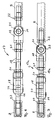
- Die Erfindung ist nachstehend anhand der Zeichnung beispielsweise näher erläutert. Diese zeigt jeweils in perspektivischer Darstellung in
- Fig. 1
- eine erfindungsgemäße Vorrichtung mit zwei gekoppelten Schub-/Dreheinheiten,
- Fig. 2
- eine einzelne Schub-/Dreheinheit,
- Fig. 3
- in Seitenansicht teilweise im Schnitt eine vorteilhafte Zahnschubstange einer erfindungsgemäßen Vorrichtung,
- Fig. 4
- in Seitenansicht einen als Augenschraube ausgebildeten Kupplungsadapter für die Zahnschubstange nach Fig. 3,
- Fig. 5
- einen als Wellenschaft ausgebildeten Kupplungsadapter für die Zahnschubstange nach Fig. 3 in Seitenansicht,
- Fig. 6
- eine mit Zahnschubstangen mit Augenschraube gekoppelte Zug-/Druck-Stange in einer besonders vorteilhaften Ausgestaltung mit einer ersten Länge,
- Fig. 7
- die Anordnung nach Fig. 6 mit einer zweiten Länge,
- Fig. 8
- ein Ausführungsbeispiel eines aus erfindungsgemäßen Vorrichtungen zusammengestellten Systems in Seitenansicht und
- Fig. 9
- das System nach Fig. 8 in Draufsicht.
- Eine erfindungsgemäße Vorrichtung zur Erzeugung von synchronen Schub-/Drehbewegungen ist in der Zeichnung allgemein mit 1 bezeichnet. Diese Vorrichtung 1 besteht aus wenigstens zwei baugleichen, aneinander gekoppelten Schub-/Dreheinheiten 2, die jeweils ein Gehäuse 3 aufweisen.
- Wie an sich bekannt, ist innerhalb jedes Gehäuses 3 der jeweiligen Schub-/Dreheinheit 2 eine Drehwelle 4 und dazu um 90° versetzt mit dieser Drehwelle in Eingriff stehend eine Zahnschubstange 5 gelagert.
- Vorteilhaft sind dabei, was zeichnerisch nicht im einzelnen dargestellt ist, die Drehwellen 4 jeweils in Wälzlagern und die Zahnschubstangen 5 jeweils in Kugelbuchsen im Gehäuse 3 gelagert.
- Jedes Gehäuse 3 weist parallel zur Drehwelle 4 auf einem gemeinsamen Radius eine Mehrzahl von Bohrungen 6 auf, derart, daß die beiden Gehäuse 3 zweier Schub-/Dreheinheiten 2 um die nicht dargestellte, drehfest mit den beiden Drehwellen 4 verbundene Antriebswelle als Drehachse zueinander beliebig verdreht angeordnet werden können. In Abhängigkeit von der jeweiligen Hubaufgabe ist es somit möglich, durch entsprechende Anordnung der beiden Gehäuse 2 zueinander unterschiedliche Winkelstellungen der beiden Zahnschubstangen 5 beider Schub-/Dreheinheiten 2 zu verwirklichen, d.h. es ist nicht nur die in Fig. 1 dargestellte rechtwinklige Anordnung möglich, sondern es läßt sich prinzipiell jede Winkelstellung zwischen den Zahnschubstangen 5 verwirklichen. Dabei ist für eine exakte Ausrichtung der beiden Schub-/Dreheinheiten 2 vorgesehen, daß die beiden Gehäuse 2 um einen nicht dargestellten gemeinsamen Zentrierring gegeneinander verdrehbar sind. Dieser Zentrierring kann jeweils entsprechend in die betreffende Ausnehmung 7 für die Drehwelle 4 eingesetzt werden.
- Um auf besonders einfache Weise eine Kopplung und drehfeste Verbindung der Drehwellen 4 mit der Antriebswelle zu erreichen, sind die Drehwellen 4 als Hohlwellen ausgebildet, wie in Fig. 2 dargestellt. Dabei sind die Hohlwellen entsprechend mit einer Profilierung versehen, z.B. als Keilwelle ausgebildet, so daß eine entsprechend außenprofilierte Antriebswelle auf einfache Weise drehfest in die Drehwellen 4 eingreifen und diese miteinander koppeln kann.
- Die Gehäuse 2 bestehen bevorzugt aus einzelnen Seitenteilen, die beispielsweise miteinander verschraubt sein können, entsprechende Bohrungen sind mit 8 angedeutet. Hier können Gußteile Verwendung finden oder es können auch entsprechende Blechformteile eingesetzt werden.
- Zusätzlich kann vorgesehen sein, daß das jeweilige Gehäuse 3 zentrisch um die Führungselemente der Zahnschubstangen 5 angeordnete Einsenkungen zur Aufnahme von Behältern für Schmierstoff aufweist, was zeichnerisch nicht dargestellt ist.
- Erkennbar besteht die erfindungsgemäße Vorrichtung 1 im wesentlichen nur aus baugleichen Schub-/Dreheinheiten 2, die prinzipiell in beliebiger Anzahl aneinandergereiht und gekoppelt werden können, d.h. hier können nicht nur zwei derartige Einheiten miteinander gekoppelt werden, wie dies in Fig. 1 dargestellt ist, sondern auch drei oder mehr, wobei dann durch entsprechende Anordnung der Gehäuse zueinander die Zahnschubstangen 5 in beliebiger Richtung orientiert angeordnet werden können und dergl. mehr.
- In Fig. 3 ist in besonders vorteilhafter Ausgestaltung eine Zahnschubstange 5 dargestellt. Diese Zahnschubstange 5 ist an beiden Kupplungsenden 9 jeweils mit einem Innengewinde 10 versehen, in welches ein Kupplungsadapter einschraubbar ist.
- Dieser Kupplungsadapter ist gemäß Ausführungsbeispiel nach Fig. 4 vorzugsweise als Augenschraube 11 ausgebildet, welche mit einem Außengewinde 12 versehen ist und in üblicher Weise einen Kopf 13 mit einer Bohrung 14 aufweist.
- Alternativ kann gemäß dem Ausführungsbeispiel nach Fig. 5 der Kupplungsadapter auch als Wellenschaft 15 ausgebildet sein, das Einschraubgewinde ist hier mit 16 bezeichnet.
- Erkennbar bietet die Ausgestaltung der Zahnschubstange 5 gemäß Fig. 3 den Vorteil, daß unterschiedliche Kupplungsadapter stirnseitig angebracht werden können oder auch weitere Vorrichtungen.
- Bei der Ausgestaltung des Kupplungsadapters als Augenschraube 11 gemäß Fig. 4 in Verbindung mit der Zahnschubstange nach Fig. 3 ist vorteilhaft auch eine Zug-/Druck-Stange 17 vorgesehen, die in Fig. 6 bzw. 7 dargestellt ist.
- Bei der Ausführungsform nach Fig. 6 weist die Zug-/Druck-Stange 17 an beiden Kupplungsenden jeweils einen Gabelkopf 18 auf, wobei beide Gabelköpfe 18 endseitig auf ein zwischen dieses befindliches Gewindestück 19 aufschraubbar sind. Die Gabelköpfe 18 sind dabei selbstverständlich so ausgelegt, daß sie verbindend mit den Augenschrauben 11 bzw. deren Köpfen 13 zusammenwirken, d.h. mit einem Verbindungsbolzen 20 gekoppelt werden können.
- Durch unterschiedliche Längenauswahl der Gewindestücke 17 bzw. 17a (Fig. 7) können auf einfache Weise unterschiedlich lange Zug-/Druck-Stangen 17 bzw. 17a erstellt werden. Dabei sind zusätzlich sowohl an den Gewindestücken 19 als auch an den Gewinden 12 der Augenschrauben 11 Kontermuttern 21 bzw. 22 vorgesehen, mittels derer eine exakte Längeneinstellung möglich ist.
- Um eine stufenlose Einstellung der Differentialkupplung in allen Längen zu gewährleisten, werden die Gewindestücke 19 vorzugsweise in konstruktiven Schritten von 100 mm ausgelegt. Durch die Auslegung der Gewindetiefen kann dazu ein Einstellbereich von 100 mm überbrückt werden. Es ist so beispielsweise möglich, dem Anwender ein Kupplungsstück in einem Einstellbereich von 280 bis 1480 mm stufenlos zur Verfügung zu stellen. Dabei werden die Kupplungsstücke bevorzugt voreingestellt geliefert.
- Die Feineinstellung durch den Monteur vor Ort wird dadurch erreicht, daß die Kontermuttern 21,22 gelöst werden und das jeweils aus Augenschraube 11 und Gabelkopf 18 bestehende Kupplungsteilstück verdreht wird.
- Durch unterschiedliche Gewindesteigungen zwischen Augenschraube 11 (vorzugsweise M20x2) und Kabelkopf (vorzugsweise M20x1,5) wird beispielsweise bei einer Drehung von 360° ein Verstellweg von 1 mm erreicht (Linksdrehung + 1 mm, Rechtsdrehung - 1 mm). Dadurch sind Einstellungsgenauigkeiten im hundertstel Millimeterbereich problemlos möglich.
- Erkennbar ist das Gesamtsystem als Stecksystem ausgelegt, was eine schnelle und sichere sowie genaue Montage ermöglicht. Außerdem ist durch ein schnelles Herauslösen einzelner Teile aus dem Gesamtsystem ein Höchstmaß an Reparaturfreundlichkeit gegeben.
- In den Fig. 8 und 9 ist beispielsweise ein aus mehreren Vorrichtungen 1 zusammengestelltes Gesamtsystem gezeigt, welches von einem Pneumatik-Zylinder 23 angetrieben wird, welcher über eine Kupplungsverbindung 24 an die Drehwelle 4 einer ersten erfindungsgemäßen Vorrichtung 1 angeschlossen ist.
- Natürlich ist die Erfindung nicht auf die dargestellten Ausführungsbeispiele beschränkt. Weitere Ausgestaltungen sind möglich, ohne den Grundgedanken zu verlassen. So lassen sich mit den erfindungsgemäßen Vorrichtungen 1 eine Vielzahl unterschiedlicher Hubsysteme erstellen.
Claims (11)
- Vorrichtung zur Erzeugung von synchronen Schub-/Drehbewegungen mit wenigstens einer Schub-/Dreheinheit mit Gehäuse, in welchem eine Drehwelle und um 90° versetzt eine mit dieser in Eingriff stehende Zahnschubstange gelagert sind,
gekennzeichnet durch
wenigstens zwei gekoppelte Schub-/Dreheinheiten (2), deren Drehwellen (4) drehfest mit einer gemeinsamen Antriebswelle verbunden sind und deren Gehäuse (3) um die Antriebswelle als Drehachse zueinander beliebig verdreht angeordnet, lösbar aneinander befestigt sind. - Vorrichtung nach Anspruch 1,
dadurch gekennzeichnet,
daß die Drehwellen (4) der Schub-/Dreheinheiten (2) als profilierte Hohlwellen ausgebildet sind, in welche die Antriebswelle drehfest eingreift. - Vorrichtung nach Anspruch 1 oder 2,
dadurch gekennzeichnet,
daß die miteinander verbundenen Gehäuse (3) um einen gemeinsamen Zentrierring gegeneinander verdrehbar sind. - Vorrichtung nach Anspruch 1 oder einem der folgenden,
dadurch gekennzeichnet,
daß die Gehäuse (3) mittels einer Verschraubung aneinander befestigt sind und daß im jeweiligen Gehäuse (3) auf einem gemeinsamen Radius um die Drehwelle (4) eine Vielzahl von Bohrungen (6) für die Verschraubung ausgebildet ist. - Vorrichtung nach Anspruch 1 oder einem der folgenden,
dadurch gekennzeichnet,
daß das jeweilige Gehäuse (3) zentrisch um die Führungselemente der Zahnschubstangen (5) angeordnete Einsenkungen zur Aufnahme von Behältern für Schmierstoff aufweist. - Vorrichtung nach Anspruch 1 oder einem der folgenden,
dadurch gekennzeichnet,
daß die Drehwellen (4) in Wälzlagern gelagert sind. - Vorrichtung nach Anspruch 1 oder einem der folgenden,
dadurch gekennzeichnet,
daß die Zahnschubstangen (5) in Kugelbuchsen gelagert sind. - Vorrichtung nach Anspruch 1 oder einem der folgenden,
dadurch gekennzeichnet,
daß die Zahnschubstangen (5) an beiden Kupplungsenden (9) mit einem Gewinde (10) versehen sind, an welches ein Kupplungsadapter (11,15) anschraubbar ist. - Vorrichtung nach Anspruch 8,
dadurch gekennzeichnet,
daß der Kupplungsadapter als Augenschraube (11) ausgebildet ist. - Vorrichtung nach Anspruch 9,
dadurch gekennzeichnet,
daß die Augenschraube (11) mit einer Zug-/Druck-Stange (17) verbindbar ist, welche an beiden Kupplungsenden jeweils einen Gabelkopf (18) aufweist und längenveränderbar ist. - Vorrichtung nach Anspruch 10,
dadurch gekennzeichnet,
daß die Zug-/Druck-Stange (17) ein Gewindestück (19) aufweist, auf welches die Gabelköpfe (18) aufschraubbar sind.
Applications Claiming Priority (2)
| Application Number | Priority Date | Filing Date | Title |
|---|---|---|---|
| DE4229601A DE4229601A1 (de) | 1992-09-04 | 1992-09-04 | Vorrichtung zur Erzeugung von synchronen Schub-/Drehbewegungen |
| DE4229601 | 1992-09-04 |
Publications (2)
| Publication Number | Publication Date |
|---|---|
| EP0585563A1 true EP0585563A1 (de) | 1994-03-09 |
| EP0585563B1 EP0585563B1 (de) | 1996-11-13 |
Family
ID=6467256
Family Applications (1)
| Application Number | Title | Priority Date | Filing Date |
|---|---|---|---|
| EP93110817A Expired - Lifetime EP0585563B1 (de) | 1992-09-04 | 1993-07-07 | Vorrichtung zur Erzeugung von synchronen Schub-/Drehbewegungen |
Country Status (4)
| Country | Link |
|---|---|
| EP (1) | EP0585563B1 (de) |
| AT (1) | ATE145267T1 (de) |
| DE (2) | DE4229601A1 (de) |
| ES (1) | ES2093891T3 (de) |
Cited By (6)
| Publication number | Priority date | Publication date | Assignee | Title |
|---|---|---|---|---|
| US5651291A (en) * | 1994-03-14 | 1997-07-29 | Lyndhurst; Richard | Crankcase forging and forming process |
| DE29816317U1 (de) * | 1998-09-13 | 2000-01-20 | Fischer, Reinhard, 72348 Rosenfeld | Außen angetriebene Verschiebeeinheit mit Querhubelement |
| DE20113552U1 (de) * | 2001-08-16 | 2002-10-31 | LEAN-Technik R. Janzen, 46047 Oberhausen | Vorrichtung zum schrittweisen Fördern von Gegenständen |
| CN106567546A (zh) * | 2016-10-26 | 2017-04-19 | 东南大学 | 一种省力式索力调节装置 |
| WO2020169133A1 (de) * | 2019-02-20 | 2020-08-27 | Schaeffler Technologies AG & Co. KG | Linearaktuator und baukasten zur herstellung dieses linearaktuator |
| US20210001479A1 (en) * | 2018-03-15 | 2021-01-07 | Igus Gmbh | Arm joint for a manipulator and manipulator |
Families Citing this family (3)
| Publication number | Priority date | Publication date | Assignee | Title |
|---|---|---|---|---|
| DE202010003450U1 (de) | 2010-03-11 | 2010-05-27 | Leantechnik Ag | Vorrichtung zur Erzeugung von synchronen Schub-/Drehbewegungen |
| DE102013210835A1 (de) * | 2013-06-11 | 2014-12-11 | Thyssenkrupp System Engineering Gmbh | Falzvorrichtung und Verfahren zum Falzen eines Werkstücks |
| DE202020104472U1 (de) | 2020-08-03 | 2021-11-05 | Leantechnik Ag | Vorrichtung zum Tragen von Bauteilen in einer Montagestraße |
Citations (6)
| Publication number | Priority date | Publication date | Assignee | Title |
|---|---|---|---|---|
| DE487204C (de) * | 1928-03-25 | 1929-12-03 | August Pfaff | Zahnstangenwinde |
| DE2236641A1 (de) * | 1971-08-10 | 1973-02-22 | Teleflex Ltd | Mechanische getriebevorrichtung |
| GB2116646A (en) * | 1982-03-17 | 1983-09-28 | Harcross Engineering | Improvements in the lubrication of rack and pinion apparatus |
| DE3732572A1 (de) * | 1986-12-03 | 1988-06-16 | Nippon Thompson Co Ltd | Geradfuehrungskugellager mit antriebseinheit |
| EP0345536A2 (de) * | 1988-06-07 | 1989-12-13 | Schwäbische Hüttenwerke Gesellschaft mit beschränkter Haftung | Linearführung |
| EP0404006A1 (de) * | 1989-06-23 | 1990-12-27 | Power Components, Inc. | Zahnstangenhubvorrichtung |
Family Cites Families (1)
| Publication number | Priority date | Publication date | Assignee | Title |
|---|---|---|---|---|
| US3400593A (en) * | 1966-03-28 | 1968-09-10 | Power Components Inc | Parts lifting equipment for die press |
-
1992
- 1992-09-04 DE DE4229601A patent/DE4229601A1/de not_active Withdrawn
-
1993
- 1993-07-07 DE DE59304464T patent/DE59304464D1/de not_active Expired - Lifetime
- 1993-07-07 AT AT93110817T patent/ATE145267T1/de active
- 1993-07-07 ES ES93110817T patent/ES2093891T3/es not_active Expired - Lifetime
- 1993-07-07 EP EP93110817A patent/EP0585563B1/de not_active Expired - Lifetime
Patent Citations (6)
| Publication number | Priority date | Publication date | Assignee | Title |
|---|---|---|---|---|
| DE487204C (de) * | 1928-03-25 | 1929-12-03 | August Pfaff | Zahnstangenwinde |
| DE2236641A1 (de) * | 1971-08-10 | 1973-02-22 | Teleflex Ltd | Mechanische getriebevorrichtung |
| GB2116646A (en) * | 1982-03-17 | 1983-09-28 | Harcross Engineering | Improvements in the lubrication of rack and pinion apparatus |
| DE3732572A1 (de) * | 1986-12-03 | 1988-06-16 | Nippon Thompson Co Ltd | Geradfuehrungskugellager mit antriebseinheit |
| EP0345536A2 (de) * | 1988-06-07 | 1989-12-13 | Schwäbische Hüttenwerke Gesellschaft mit beschränkter Haftung | Linearführung |
| EP0404006A1 (de) * | 1989-06-23 | 1990-12-27 | Power Components, Inc. | Zahnstangenhubvorrichtung |
Cited By (7)
| Publication number | Priority date | Publication date | Assignee | Title |
|---|---|---|---|---|
| US5651291A (en) * | 1994-03-14 | 1997-07-29 | Lyndhurst; Richard | Crankcase forging and forming process |
| DE29816317U1 (de) * | 1998-09-13 | 2000-01-20 | Fischer, Reinhard, 72348 Rosenfeld | Außen angetriebene Verschiebeeinheit mit Querhubelement |
| DE20113552U1 (de) * | 2001-08-16 | 2002-10-31 | LEAN-Technik R. Janzen, 46047 Oberhausen | Vorrichtung zum schrittweisen Fördern von Gegenständen |
| CN106567546A (zh) * | 2016-10-26 | 2017-04-19 | 东南大学 | 一种省力式索力调节装置 |
| US20210001479A1 (en) * | 2018-03-15 | 2021-01-07 | Igus Gmbh | Arm joint for a manipulator and manipulator |
| US11865712B2 (en) * | 2018-03-15 | 2024-01-09 | Igus Gmbh | Arm joint for a manipulator and manipulator |
| WO2020169133A1 (de) * | 2019-02-20 | 2020-08-27 | Schaeffler Technologies AG & Co. KG | Linearaktuator und baukasten zur herstellung dieses linearaktuator |
Also Published As
| Publication number | Publication date |
|---|---|
| ES2093891T3 (es) | 1997-01-01 |
| ATE145267T1 (de) | 1996-11-15 |
| EP0585563B1 (de) | 1996-11-13 |
| DE59304464D1 (de) | 1996-12-19 |
| DE4229601A1 (de) | 1994-03-10 |
Similar Documents
| Publication | Publication Date | Title |
|---|---|---|
| DE19521710B4 (de) | Panoramakopf für optische Geräte, insbesondere für Fotoapparate | |
| DE69215273T2 (de) | Linearschlitten | |
| DE4335092C2 (de) | Vorschubvorrichtung für ein bewegliches Teil | |
| EP0868964A1 (de) | Vorrichtung zur Erzeugung einer definierten Positionierung und Orientierung mindestens einer Plattform | |
| DE10015340A1 (de) | Walzgerüst für Walzstraßen zum Walzen von metallischen Rohren, Stäben oder Drähten | |
| EP0041136A1 (de) | Schwenkantrieb für schwenkbar gelagerte Maschinenteile, insbesondere bei Manipulatoren | |
| EP0585563B1 (de) | Vorrichtung zur Erzeugung von synchronen Schub-/Drehbewegungen | |
| DE1527181B1 (de) | Gewindebohrmaschine | |
| DE19937783A1 (de) | Druckwerk | |
| DE19730500A1 (de) | Auszugsystem | |
| EP1075943A1 (de) | Druckwerk | |
| EP0345536B1 (de) | Linearführung | |
| DE69400764T2 (de) | Mechanismus zur Umwandlung einer drehenden in eine geradlinige Bewegung | |
| DE2319775C3 (de) | Gegenüber mehreren Bezugsachsen einstellbare Vorrichtung für einen in einem Haltering gelagerten Gegenstand | |
| DE1096159B (de) | Vorschubeinrichtung mit einer Vorschubspindel und einer nachstellbaren Vorschubmutter | |
| DE2920684A1 (de) | Halterung fuer wendestangen in druckmaschinen | |
| DE3142572C2 (de) | Vorrichtung zum lösbaren Verbinden von Seilenden, insbesondere von Seilen bei umlaufenden Seiltrieben, Seilförderern oder Aufhängungen | |
| DE3883191T2 (de) | Vorrichtung zur Hubverstellung in einer Presse. | |
| DE3315698A1 (de) | Federstuetze mit konstanter tragkraft | |
| DE3303908C1 (de) | Vorrichtung zur Handhabung von Werkstuecken,Montageteilen oder dergleichen | |
| DE2461084C3 (de) | Druckmittelbetriebene Stellvorrichtung für lineare und/oder drehende Bewegungen | |
| EP1247477A2 (de) | Elektromotorischer Stelltrieb | |
| DE3013957A1 (de) | Gesenk-auswechselvorrichtung | |
| DE2920701C2 (de) | Halterung für eine Wendestange in einer Druckmaschine | |
| DE9190121U1 (de) | Aufspannvorrichtung für Werkzeugmaschinen |
Legal Events
| Date | Code | Title | Description |
|---|---|---|---|
| PUAI | Public reference made under article 153(3) epc to a published international application that has entered the european phase |
Free format text: ORIGINAL CODE: 0009012 |
|
| AK | Designated contracting states |
Kind code of ref document: A1 Designated state(s): AT BE DE ES FR GB IT NL PT SE |
|
| 17P | Request for examination filed |
Effective date: 19940812 |
|
| 17Q | First examination report despatched |
Effective date: 19950620 |
|
| GRAG | Despatch of communication of intention to grant |
Free format text: ORIGINAL CODE: EPIDOS AGRA |
|
| GRAH | Despatch of communication of intention to grant a patent |
Free format text: ORIGINAL CODE: EPIDOS IGRA |
|
| GRAH | Despatch of communication of intention to grant a patent |
Free format text: ORIGINAL CODE: EPIDOS IGRA |
|
| GRAA | (expected) grant |
Free format text: ORIGINAL CODE: 0009210 |
|
| STAA | Information on the status of an ep patent application or granted ep patent |
Free format text: STATUS: THE PATENT HAS BEEN GRANTED |
|
| AK | Designated contracting states |
Kind code of ref document: B1 Designated state(s): AT BE DE ES FR GB IT NL PT SE |
|
| REF | Corresponds to: |
Ref document number: 145267 Country of ref document: AT Date of ref document: 19961115 Kind code of ref document: T |
|
| REF | Corresponds to: |
Ref document number: 59304464 Country of ref document: DE Date of ref document: 19961219 |
|
| REG | Reference to a national code |
Ref country code: ES Ref legal event code: FG2A Ref document number: 2093891 Country of ref document: ES Kind code of ref document: T3 |
|
| ET | Fr: translation filed | ||
| ITF | It: translation for a ep patent filed | ||
| GBT | Gb: translation of ep patent filed (gb section 77(6)(a)/1977) |
Effective date: 19970129 |
|
| REG | Reference to a national code |
Ref country code: PT Ref legal event code: SC4A Free format text: AVAILABILITY OF NATIONAL TRANSLATION Effective date: 19961119 |
|
| PLBE | No opposition filed within time limit |
Free format text: ORIGINAL CODE: 0009261 |
|
| 26N | No opposition filed | ||
| PLAA | Information modified related to event that no opposition was filed |
Free format text: ORIGINAL CODE: 0009299DELT |
|
| RIN2 | Information on inventor provided after grant (corrected) |
Free format text: HUETKER, KLAUS, DIPL.-ING. * JANZEN, REINHARD |
|
| REG | Reference to a national code |
Ref country code: GB Ref legal event code: IF02 |
|
| REG | Reference to a national code |
Ref country code: PT Ref legal event code: MM4A Free format text: LAPSE DUE TO NON-PAYMENT OF FEES Effective date: 20090107 |
|
| REG | Reference to a national code |
Ref country code: PT Ref legal event code: NF4A Free format text: RESTITUTIO IN INTEGRUM Effective date: 20090303 |
|
| PGRI | Patent reinstated in contracting state [announced from national office to epo] |
Ref country code: PT Effective date: 20090303 |
|
| PGFP | Annual fee paid to national office [announced via postgrant information from national office to epo] |
Ref country code: GB Payment date: 20120723 Year of fee payment: 20 Ref country code: SE Payment date: 20120723 Year of fee payment: 20 |
|
| PGFP | Annual fee paid to national office [announced via postgrant information from national office to epo] |
Ref country code: DE Payment date: 20120616 Year of fee payment: 20 Ref country code: IT Payment date: 20120725 Year of fee payment: 20 Ref country code: FR Payment date: 20120803 Year of fee payment: 20 Ref country code: BE Payment date: 20120724 Year of fee payment: 20 Ref country code: ES Payment date: 20120723 Year of fee payment: 20 |
|
| PGFP | Annual fee paid to national office [announced via postgrant information from national office to epo] |
Ref country code: NL Payment date: 20120718 Year of fee payment: 20 Ref country code: PT Payment date: 20120109 Year of fee payment: 20 |
|
| PGFP | Annual fee paid to national office [announced via postgrant information from national office to epo] |
Ref country code: AT Payment date: 20120720 Year of fee payment: 20 |
|
| REG | Reference to a national code |
Ref country code: DE Ref legal event code: R071 Ref document number: 59304464 Country of ref document: DE |
|
| REG | Reference to a national code |
Ref country code: DE Ref legal event code: R071 Ref document number: 59304464 Country of ref document: DE |
|
| REG | Reference to a national code |
Ref country code: PT Ref legal event code: MM4A Free format text: MAXIMUM VALIDITY LIMIT REACHED Effective date: 20130707 |
|
| REG | Reference to a national code |
Ref country code: NL Ref legal event code: V4 Effective date: 20130707 |
|
| BE20 | Be: patent expired |
Owner name: *LEAN-TECHNIK R. JANZEN Effective date: 20130707 |
|
| REG | Reference to a national code |
Ref country code: GB Ref legal event code: PE20 Expiry date: 20130706 |
|
| REG | Reference to a national code |
Ref country code: AT Ref legal event code: MK07 Ref document number: 145267 Country of ref document: AT Kind code of ref document: T Effective date: 20130707 |
|
| REG | Reference to a national code |
Ref country code: SE Ref legal event code: EUG |
|
| PG25 | Lapsed in a contracting state [announced via postgrant information from national office to epo] |
Ref country code: DE Free format text: LAPSE BECAUSE OF EXPIRATION OF PROTECTION Effective date: 20130709 Ref country code: PT Free format text: LAPSE BECAUSE OF EXPIRATION OF PROTECTION Effective date: 20130716 |
|
| PG25 | Lapsed in a contracting state [announced via postgrant information from national office to epo] |
Ref country code: GB Free format text: LAPSE BECAUSE OF EXPIRATION OF PROTECTION Effective date: 20130706 |
|
| REG | Reference to a national code |
Ref country code: ES Ref legal event code: FD2A Effective date: 20140828 |
|
| PG25 | Lapsed in a contracting state [announced via postgrant information from national office to epo] |
Ref country code: ES Free format text: LAPSE BECAUSE OF EXPIRATION OF PROTECTION Effective date: 20130708 |
|
| RIC2 | Information provided on ipc code assigned after grant |
Ipc: F16H 19/00 20060101ALI19931111BHEP Ipc: F16H 57/02 20120101AFI19931111BHEP |