EP0585582B1 - Dispositif pour stimuler du tissu viviant - Google Patents
Dispositif pour stimuler du tissu viviant Download PDFInfo
- Publication number
- EP0585582B1 EP0585582B1 EP93111476A EP93111476A EP0585582B1 EP 0585582 B1 EP0585582 B1 EP 0585582B1 EP 93111476 A EP93111476 A EP 93111476A EP 93111476 A EP93111476 A EP 93111476A EP 0585582 B1 EP0585582 B1 EP 0585582B1
- Authority
- EP
- European Patent Office
- Prior art keywords
- control
- measurement
- control signals
- switching device
- stimulation
- Prior art date
- Legal status (The legal status is an assumption and is not a legal conclusion. Google has not performed a legal analysis and makes no representation as to the accuracy of the status listed.)
- Expired - Lifetime
Links
- 230000004936 stimulating effect Effects 0.000 title claims description 4
- 230000000638 stimulation Effects 0.000 claims description 81
- 238000005259 measurement Methods 0.000 claims description 50
- 239000003990 capacitor Substances 0.000 claims description 13
- 230000005540 biological transmission Effects 0.000 claims description 7
- 238000010586 diagram Methods 0.000 description 5
- 210000002837 heart atrium Anatomy 0.000 description 3
- 230000006872 improvement Effects 0.000 description 2
- QVGXLLKOCUKJST-UHFFFAOYSA-N atomic oxygen Chemical compound [O] QVGXLLKOCUKJST-UHFFFAOYSA-N 0.000 description 1
- 230000008901 benefit Effects 0.000 description 1
- 239000008280 blood Substances 0.000 description 1
- 210000004369 blood Anatomy 0.000 description 1
- 238000003745 diagnosis Methods 0.000 description 1
- 230000000694 effects Effects 0.000 description 1
- 238000012544 monitoring process Methods 0.000 description 1
- 229910052760 oxygen Inorganic materials 0.000 description 1
- 239000001301 oxygen Substances 0.000 description 1
- 230000004044 response Effects 0.000 description 1
- 230000008054 signal transmission Effects 0.000 description 1
- 230000001225 therapeutic effect Effects 0.000 description 1
Images

Classifications
-
- A—HUMAN NECESSITIES
- A61—MEDICAL OR VETERINARY SCIENCE; HYGIENE
- A61N—ELECTROTHERAPY; MAGNETOTHERAPY; RADIATION THERAPY; ULTRASOUND THERAPY
- A61N1/00—Electrotherapy; Circuits therefor
- A61N1/18—Applying electric currents by contact electrodes
- A61N1/32—Applying electric currents by contact electrodes alternating or intermittent currents
- A61N1/36—Applying electric currents by contact electrodes alternating or intermittent currents for stimulation
- A61N1/362—Heart stimulators
- A61N1/365—Heart stimulators controlled by a physiological parameter, e.g. heart potential
- A61N1/368—Heart stimulators controlled by a physiological parameter, e.g. heart potential comprising more than one electrode co-operating with different heart regions
- A61N1/3686—Heart stimulators controlled by a physiological parameter, e.g. heart potential comprising more than one electrode co-operating with different heart regions configured for selecting the electrode configuration on a lead
-
- A—HUMAN NECESSITIES
- A61—MEDICAL OR VETERINARY SCIENCE; HYGIENE
- A61N—ELECTROTHERAPY; MAGNETOTHERAPY; RADIATION THERAPY; ULTRASOUND THERAPY
- A61N1/00—Electrotherapy; Circuits therefor
- A61N1/18—Applying electric currents by contact electrodes
- A61N1/32—Applying electric currents by contact electrodes alternating or intermittent currents
- A61N1/36—Applying electric currents by contact electrodes alternating or intermittent currents for stimulation
- A61N1/3605—Implantable neurostimulators for stimulating central or peripheral nerve system
- A61N1/36128—Control systems
- A61N1/36146—Control systems specified by the stimulation parameters
- A61N1/36182—Direction of the electrical field, e.g. with sleeve around stimulating electrode
- A61N1/36185—Selection of the electrode configuration
-
- A—HUMAN NECESSITIES
- A61—MEDICAL OR VETERINARY SCIENCE; HYGIENE
- A61N—ELECTROTHERAPY; MAGNETOTHERAPY; RADIATION THERAPY; ULTRASOUND THERAPY
- A61N1/00—Electrotherapy; Circuits therefor
- A61N1/18—Applying electric currents by contact electrodes
- A61N1/32—Applying electric currents by contact electrodes alternating or intermittent currents
- A61N1/36—Applying electric currents by contact electrodes alternating or intermittent currents for stimulation
- A61N1/362—Heart stimulators
- A61N1/365—Heart stimulators controlled by a physiological parameter, e.g. heart potential
-
- A—HUMAN NECESSITIES
- A61—MEDICAL OR VETERINARY SCIENCE; HYGIENE
- A61N—ELECTROTHERAPY; MAGNETOTHERAPY; RADIATION THERAPY; ULTRASOUND THERAPY
- A61N1/00—Electrotherapy; Circuits therefor
- A61N1/18—Applying electric currents by contact electrodes
- A61N1/32—Applying electric currents by contact electrodes alternating or intermittent currents
- A61N1/36—Applying electric currents by contact electrodes alternating or intermittent currents for stimulation
- A61N1/372—Arrangements in connection with the implantation of stimulators
Definitions
- the invention relates to a device for stimulating living tissue, comprising a stimulation unit which emits stimulation pulses over a pulse signal output socket, an electrode system which delivers the stimulation pulses to the living tissue, a controllable switching device through which the electrode system is connected to the pulse signal output socket to transmit the stimulation pulses to a specific part of the electrode system and a control device which emits control signals over a control output socket to a control input socket on the switching device to control transmission of stimulation pulses.
- the known device contains a pacemaker, a switching unit and an electrode system.
- the electrode system consists of two multipolar electrodes which can be unipolarly or bipolarly connected to the pacemaker via the switching unit.
- the switching unit is controllable and directly controlled from pacemaker electronic circuitry via control lines. With the aid of the switch, the required number of feedthroughs to pacemaker electronic circuitry, which is enclosed in a pacemaker case, can be reduced.
- one feedthrough is employed for delivering stimulation pulses from pacemaker electronic circuitry and control lines for controlling the switch.
- a serial-to-parallel signal converter is employed in the switching unit to reduce to one the number of control lines to pacemaker electronic circuitry.
- An object of the invention is to produce a device as described above in which the number of leads is further reduced. Another object is to separate and mount the switching device near the electrodes.
- a device is produced which can easily be adapted to a plurality of functions in e.g. the diagnosis or therapeutic treatment of living tissue.
- control device's control output socket is coupled to the pulse signal output socket
- switching device is external to the stimulation unit
- the switching device's control input socket is coupled by an elongate connection to the pulse signal output socket and the switching device contains a signal discriminator to separate control signals from stimulation pulses so they control the switching device's transmission of the stimulation pulses.
- the number of feedthrough leads is hereby minimized.
- a unipolar device one lead is sufficient through which stimulation pulses and control signals are transmitted to the switching device and on to the electrode system.
- a bipolar device has two leads.
- the signal discriminator discriminates the different types of signals and separates them so that the control signal can be used for controlling the switching device's setting.
- a plurality of electrodes can be placed in a heart and connected to the pacemaker via the switching device.
- the heart's response to stimulation pulses at different locations in the heart can be easily studied so as to e.g. ascertain the best site for a permanently implanted electrode.
- control signals and stimulation pulses have different polarities, and the signal discriminator senses polarity in order to distinguish control signals from stimulation pulses.
- control signals make it easy to distinguish between the types of signal. Irrespective of whether the same or different polarities are used for the signals, it is advantageous for the control signals to have an amplitude lower than the threshold value required to stimulate the living tissue, since there would then be no risk of erroneous tissue stimulation caused by control signals sent to the electrode system.
- the signals can be discriminated when the control device contains a modulator to modulate the stimulation pulses with the control signals, and the signal discriminator contains a demodulator to separate control signals from stimulation pulses.
- An improvement of the device is achieved in accordance with a preferred embodiment of the invention in that at least one measurement device is coupled, over the switching device, to the pulse signal output socket, whereby the control device, by means of a control signal, closes a signal connection between the measurement device and a measurement appliance in the stimulation unit.
- the device can be expanded into a multifunctional unit capable of stimulating tissue and measuring physiological variables in stimulated or other tissue.
- the measured variables can be used by the stimulation unit for enhanced monitoring and control of tissue stimulation.
- Physiological variables which can be measured are e.g. temperature, blood oxygen, tissue impedance and movements.
- the measurement device it is advantageous for the measurement device to be controllable, for the control device to emit measurement control signals and for the signal discriminator to be devised to distinguish between control signals and measurement control signals so control signals control the switching device's transmission of measurement control signals to the measurement device.
- the stimulation unit then provides complete control over all functional units in the device.
- the control signals open different connections between the stimulation unit and the electrode system or the measurement device over the switching device.
- the stimulation unit can control the measurement device's measurement of the physiological variable and receive the measurement signals from the measurement device in order to vary stimulation of the living tissue on the basis thereof.
- the switching device contains a power supply input socket connected to the pulse signal output socket
- the stimulation unit contains a power source which delivers power to the power supply input socket.
- power can be transmitted as a supply current to the power supply input socket in the switching device, or the switching device can contain a capacitor connected to the power supply input socket through which the power source charges the capacitor.
- One advantage in this context is that the power source is connected to the measurement device over the switching device, and the power source supplies current for the measurement device's power needs when the connection between the power source and the measurement device is closed.
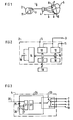
- the device 1 in FIG. 1 has a stimulation unit 2 in the form of a pacemaker which is connected, through a socket 3 over a switching device 4, to a heart 5 by an electrode system 6.
- the stimulation unit 2 could also have been a defibrillator or a cardioverter but, for the sake of simplicity, will only be described henceforth as a pacemaker 2.
- the electrode system 6 consists of a first tip electrode 7 and a second tip electrode 8 placed in the atrium of the heart 5, a third tip electrode 9 and a fourth tip electrode 10 placed in the ventricle of the heart 5.
- the pacemaker 2 is unipolarly coupled and has an indifferent electrode 11 on the exterior of the pacemaker 2 to conduct stimulation pulses back to the pacemaker from the electrode system 6.
- a stimulation pulse is generated by the pacemaker 2 and sent, along with a control signal, to the switching device 4.
- the control signal affects the switching device 4 in such a way that the stimulation pulse is sent to one of the tip electrodes 7 - 10 in the electrode system 6 and delivered to the heart 5.
- the stimulation pulse is then conducted over body tissue back to the indifferent electrode 11 and the pacemaker 2.
- FIG. 2 shows a block diagram of the pacemaker 2, containing a pulse generator 12 connected to the pulse signal output socket 3 and the indifferent electrode 11, and a measurement appliance 13 which is also connected to the pulse signal output socket 3 and the indifferent electrode 11.
- the pulse generator 12 generates the stimulation pulses.
- the measurement appliance 13 senses the heart's electrical activity after the switching device 4 closes a connection between the pacemaker 2 and the electrode system 6.
- a control device 14 controls, via a data bus 15, the pulse generator 12 and the measurement appliance 13. Stimulation pulses can be modulated with control signals in a modulator 16.
- the modulator 16 is also connected to the control device 14 via the data bus 15.
- a physician can program the control device 14 to perform various functions.
- the telemetry unit 17 is also connected to the data bus 15. Power for the pacemaker 2 is supplied by a battery 19.
- stimulation pulses with superimposed control signals are sent by the pulse generator 12 over the pulse signal output socket 3 to the switching device 4.
- the signals are sent via a signal input socket 20 to a signal discriminator 21 which demodulates the control signal and feeds it to a control appliance 22 for controlling a switch 23.
- the switch 23 has four output positions 23A - D connected to the first tip electrode 7, the second tip electrode 8, the third tip electrode 9 and the fourth tip electrode 10 respectively.
- a line 24 connects the switch 23 to the signal input socket 20 to transmit stimulation pulses across the switch 23 to the selected electrode tip.
- the switching device 4 also contains a diode 25 and a capacitor connected in parallel over the line 24 to drive the switching device 4.
- the diode 25 is connected to the signal input socket 20 and to the capacitor 26 which is connected in parallel across the switching device's 4 power supply input socket 27.
- An energy pulse whose polarity is opposite to the polarity of the stimulation pulses, is emitted to charge the capacitor 26 with the energy required to drive the switching device 4.
- FIG. 4 shows a first stimulation pulse 28 with a superimposed control signal 29.
- the stimulation pulse 28 is generated by the pulse generator 12 with an amplitude and duration controlled by the control device 14.
- the modulator 16 modulates the control signal 29 over the first part of the stimulation pulse 28.
- the stimulation pulse 28 is sent over the pulse signal output socket 3 to the switching device's 4 signal input socket 20.
- the control signal is demodulated in the signal discriminator and fed to the control appliance 22 which sends a switching signal to the switch 23.
- the control signal indicates that the switch 23 must enable output position 23A which is connected to the first tip electrode 7.
- the stimulation pulse 28 is sent from the signal input socket 20 over line 24 to switch 23 and out through output position 23A to the first tip electrode 7 which delivers the stimulation pulse 28 to the heart 5.
- the stimulation pulse 28 is then conducted through body tissue back to the indifferent electrode 11 and the pulse generator 12.
- FIG. 5 shows a second stimulation pulse 30 which contains a first control signal in the form of a pulse package 31, a first stimulation pulse part 32, a second control signal in the form of a pulse package 33 and a second stimulation pulse part 34.
- the first control signal 31 can e.g. cause transmission of the first stimulation pulse part 31 to the heart 5 over the third tip electrode 9, and the second control signal 33 sets the switch 23 in such a way that the second stimulation pulse part 34 is delivered to the heart 5 over the fourth tip electrode 10.
- FIG. 6 shows a third stimulation pulse 35 in which the control signal 36 consists of a high-frequency signal superimposed on the stimulation pulse 35.
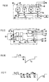
- the device 37 comprises a pacemaker 38 for bipolar operation which is connected, over a pulse signal output socket 39 and a switching device 40, to a first measurement device 41, a second measurement device 42 and, through an electrode system 44, a heart 43.
- the pacemaker 38 has an indifferent electrode 49 on its case.
- the electrode system 44 consists of a first tip electrode 45 and a first ring electrode 46 placed in the atrium of the heart 43, and a second tip electrode 47 and a second ring electrode 48 placed in the ventricle of the heart 43.
- a stimulation pulse generated by the pacemaker 38 and a control signal are simultaneously emitted and act on the switch 40 to open a connection with e.g. the second tip electrode 47, which delivers the stimulation pulse to the heart 43, and the second ring electrode 48 over which the stimulation pulse is conducted back to the pacemaker 38.
- the pacemaker 38 contains, like the pacemaker 2 in FIG. 2, a pulse generator 50, a measurement appliance 51, a control device 52 and a telemetry unit 53, all connected to each other via a data bus 54.
- the telemetry unit 53 transmits programming and information between the control device 52 and a programming unit 55.
- the pacemaker 38 also contains a control signal generator 56 and a power source 57, both connected to the pulse signal output socket 39.
- the pulse generator 50, the control signal generator 56 and the power source 57 are shown here as three separate units for the sake of clarity but could also consist of a single unit. All pacemaker electronic circuitry is supplied with power by the battery 58.
- the control device 52 controls the switching device 40 to connect the first measurement device 41 or the second measurement device 42 or any of the electrode system's 44 electrodes 45, 46, 47, 48 to the pulse signal output socket 39.
- the switching device 40 has a signal input socket 59 which is connected to the pulse signal output socket 39 and which conducts signals from the pulse signal output socket 39 to a signal discriminator 60 to separate the control signal and send it to a control appliance 61.
- the control appliance 61 controls a first switch 62 and a second switch 63.
- the first switch 61 has five output positions 62A - E, the first output position 62A connected to the first measurement device 41, the second output position 62B connected to the second measurement device 42, the third output position 62C connected to the first tip electrode 45 and the fourth output position 62D connected to the second tip electrode 47, the fifth output position 62E having no connection.
- the second switch 63 has three output positions 63A - C, the first output position 63A connected to the first ring electrode 46, the second output position 63B connected to the second ring electrode 48, the third output position 63C having no connection.
- a first line 64 connects the signal input socket 59 to the first switch 62, and a second line 65 connects the signal input socket 59 to the second switch 63.
- a diode 66 and a capacitor 67 are connected in parallel over the signal input socket 59, the capacitor 67 being charged from the pacemaker 38 in order to supply the switching device 40 with power through a power supply input socket 68.
- FIG. 10 shows an energy pulse 70, generated by the power source 57, to charge the capacitor 67.
- the switching device 40 is in its output mode, i.e. the first switch 62 is in its fifth position 62E and the second switch 63 is in its third position 63C.
- a control signal 69 follows the energy pulse 70 and causes the first switch 62 to be set at its third position 62C in order to send the stimulation pulse 71 to the first tip electrode 45 and set the second switch 63 to its first position 63A so as to conduct the stimulation pulse 71 back to the pulse generator 50 over the first ring electrode 46 and the switching device 40.
- the stimulation pulse 71 can also be emitted unipolarly, whereby the second switch 63 is set at its third output position 63C, and the connection between the indifferent electrode 49 and the pulse generator 50 is closed.
- FIG. 11 shows a first energy pulse 73a for charging the capacitor 67.
- a first control signal 72a closes the connection between the measurement appliance 51 and the first measurement device 41, a measurement signal 74a then being transmitted from the first measurement device 41 to the measurement appliance 51.
- a second control signal 72b sets the switch 62 in such a way that the connection to the second control device 42 is closed.
- the measurement appliance 57 emits a second energy pulse 73b followed by a measurement control signal 74b generated by the power source 57 in order to supply the second measurement device 42 with power and control same.
- the second measurement device 42 can have a capacitor which is charged by the second energy pulse 73b.
- a third control signal 72d causes the connection with the second tip electrode 47 and the second ring electrode 48 to close so a stimulation pulse 75 is delivered to the heart 43.
- the switches 23, 62, 63 in FIGS. 3 and 9 can be devised with e.g. transistors or in some other known manner.
- Power for the switching device 40 can also be provided in some way other than with a capacitor 67 which is charged, viz. by having the power source 57 emit a supply current sufficient to cover the switching device's 40 power needs.
Landscapes
- Health & Medical Sciences (AREA)
- Life Sciences & Earth Sciences (AREA)
- Heart & Thoracic Surgery (AREA)
- Cardiology (AREA)
- Public Health (AREA)
- Radiology & Medical Imaging (AREA)
- Animal Behavior & Ethology (AREA)
- General Health & Medical Sciences (AREA)
- Nuclear Medicine, Radiotherapy & Molecular Imaging (AREA)
- Veterinary Medicine (AREA)
- Biomedical Technology (AREA)
- Engineering & Computer Science (AREA)
- Biophysics (AREA)
- Physiology (AREA)
- Neurology (AREA)
- Neurosurgery (AREA)
- Electrotherapy Devices (AREA)
Claims (10)
- Dispositif (1 ; 37) pour stimuler un tissu (5 ; 43) vivant comprenant une unité (2 ; 38) de stimulation qui émet des impulsions de stimulation par l'intermédiaire d'une fiche (3 ; 39) de sortie de signal impulsionnel, un système (6 ; 44) d'électrodes qui délivre les impulsions de stimulation au tissu (5 ; 54) vivant, un dispositif (4, 40) de commutation pouvant être commandé, par l'intermédiaire duquel le système (6 ; 44) d'électrodes est connecté à la fiche (3 ; 39) de sortie de signal impulsionnel pour transmettre les impulsions de stimulation à une partie spécifique du système (6 ; 44) d'électrodes et un dispositif (12, 14 ; 52, 56) de commande qui émet des signaux de commande par l'intermédiaire d'une fiche de sortie de commande à une fiche (20 ; 59) d'entrée de commande se trouvant sur le dispositif (4 ; 40) de commutation pour commander la transmission des impulsions de stimulation, caractérisé en ce que la fiche de sortie de commande du dispositif (12, 14 ; 52, 56) de commande est connectée à la fiche (3 ; 39) de sortie de signal impulsionnel, en ce que le dispositif (4 ; 40) de commutation est extérieur à l'unité (2) de stimulation, en ce que la fiche (20 ; 59) d'entrée de commande du dispositif (4 ; 40) de commutation est connectée à la fiche (3 ; 39) de sortie de signal impulsionnel, et en ce que le dispositif (4 ; 40) de commutation contient un discriminateur (21 ; 60) de signaux pour distinguer des signaux de commande des impulsions de stimulation afin que les signaux de commande commandent la transmission par le dispositif (4; 40) de commutation d'impulsions de stimulation.
- Dispositif suivant la revendication 1, dans lequel des signaux de commande et des impulsions de stimulation ont des polarités différentes, et le discriminateur (21 ; 60) de signaux détecte la polarité afin de distinguer des signaux de commande des impulsions de stimulation.
- Dispositif suivant la revendication 1 ou 2, dans lequel des signaux de commande ont une amplitude inférieure à la valeur de seuil requise pour stimuler le tissu (5 ; 43) vivant.
- Dispositif suivant la revendication 1, dans lequel le dispositif (12, 14 ; 52, 56) de commande contient un modulateur (16 ; 56) destiné à moduler les impulsions de stimulation avec les signaux de commande, et le discriminateur (21 ; 60) de signaux contient un démodulateur pour distinguer des signaux de commande des impulsions de stimulation.
- Dispositif suivant l'une quelconque des revendications précédentes, dans lequel au moins un dispositif (41 ; 42) de mesure est relié, par l'intermédiaire du dispositif (40) de commutation, à la fiche (39) de sortie de signal impulsionnel, le dispositif (52, 56) de commande fermant alors, au moyen d'un signal de commande, une connexion de signal entre le dispositif (41, 42) de mesure et un instrument (51) de mesure se trouvant dans l'unité (38) de stimulation.
- Dispositif suivant la revendication 5, dans lequel le dispositif (41 ; 42) de mesure peut être commandé, le dispositif (52, 56) de commande émet des signaux de commande de mesure et le discriminateur (60) de signaux est conçu pour établir une distinction entre des signaux de commande et des signaux de commande de mesure afin que des signaux de commande commandent la transmission par le dispositif (40) de commutation de signaux de commande de mesure au dispositif (41, 42) de mesure.
- Dispositif suivant l'une quelconque des revendications précédentes, dans lequel le dispositif (4 ; 40) de commutation contient une fiche (27 ; 68) d'entrée d'alimentation électrique connectée à la fiche (3 ; 39) de sortie de signal impulsionnel, et l'unité (2 ; 38) de stimulation contient une source (57) d'énergie électrique qui fournit de l'énergie électrique à la fiche (27 ; 68) d'entrée d'alimentation électrique.
- Dispositif suivant la revendication 7, dans lequel la source (57) d'énergie électrique fournit un courant électrique à la fiche (27 ; 68) d'entrée d'alimentation électrique.
- Dispositif suivant la revendication 7, dans lequel le dispositif (4 ; 40) de commutation contient un condensateur (26 ; 67) connecté à la fiche (27 ; 68) d'entrée d'alimentation électrique par l'intermédiaire de laquelle la source (57) d'énergie électrique charge le condensateur (26 ; 67).
- Dispositif suivant l'une quelconque des revendications 7 à 9 de combinaison avec la revendication 5 ou 6, dans lequel la source (57) d'énergie électrique est connectée au dispositif (41 ; 42) de mesure par l'intermédiaire du dispositif (40) de commutation, et la source (57) d'énergie électrique fournit un courant pour les besoins en énergie du dispositif (41 ; 42) de mesure lorsque la connexion entre la source (57) énergie électrique et le dispositif (41 ; 42) de mesure est fermée.
Applications Claiming Priority (2)
| Application Number | Priority Date | Filing Date | Title |
|---|---|---|---|
| SE9202521 | 1992-09-02 | ||
| SE9202521A SE9202521D0 (sv) | 1992-09-02 | 1992-09-02 | Anordning foer stimulering av levande vaevnad |
Publications (2)
| Publication Number | Publication Date |
|---|---|
| EP0585582A1 EP0585582A1 (fr) | 1994-03-09 |
| EP0585582B1 true EP0585582B1 (fr) | 1998-03-11 |
Family
ID=20387073
Family Applications (1)
| Application Number | Title | Priority Date | Filing Date |
|---|---|---|---|
| EP93111476A Expired - Lifetime EP0585582B1 (fr) | 1992-09-02 | 1993-07-16 | Dispositif pour stimuler du tissu viviant |
Country Status (5)
| Country | Link |
|---|---|
| US (2) | US5423873A (fr) |
| EP (1) | EP0585582B1 (fr) |
| JP (1) | JPH06154344A (fr) |
| DE (1) | DE69317338T2 (fr) |
| SE (1) | SE9202521D0 (fr) |
Families Citing this family (54)
| Publication number | Priority date | Publication date | Assignee | Title |
|---|---|---|---|---|
| US5411528A (en) * | 1992-11-19 | 1995-05-02 | Pacesetter, Inc. | Electrically programmable polarity connector for an implantable body tissue stimulator |
| WO1997037720A1 (fr) * | 1996-04-04 | 1997-10-16 | Medtronic, Inc. | Technique de stimulation et d'enregistrement pour tissus vivants |
| FR2796562B1 (fr) | 1996-04-04 | 2005-06-24 | Medtronic Inc | Techniques de stimulation d'un tissu vivant et d'enregistrement avec commande locale de sites actifs |
| US5800465A (en) * | 1996-06-18 | 1998-09-01 | Medtronic, Inc. | System and method for multisite steering of cardiac stimuli |
| SE9602846D0 (sv) * | 1996-07-23 | 1996-07-23 | Pacesetter Ab | A stimulation device |
| US5987354A (en) * | 1996-08-13 | 1999-11-16 | Uab Research Foundation | Dual shock atrial defibrillation apparatus |
| US6006131A (en) * | 1996-08-13 | 1999-12-21 | Uab Research Foundation | Dual current pathway atrial defibrillation apparatus |
| US5999848A (en) * | 1997-09-12 | 1999-12-07 | Alfred E. Mann Foundation | Daisy chainable sensors and stimulators for implantation in living tissue |
| US6259937B1 (en) * | 1997-09-12 | 2001-07-10 | Alfred E. Mann Foundation | Implantable substrate sensor |
| SE9800566D0 (sv) * | 1998-02-25 | 1998-02-25 | Pacesetter Ab | Implantable lead and medical device |
| US5999853A (en) * | 1998-03-02 | 1999-12-07 | Vitatron Medical, B.V. | Dual chamber pacemaker with single pass lead and with bipolar and unipolar signal processing capability |
| DE19930265A1 (de) * | 1999-06-25 | 2000-12-28 | Biotronik Mess & Therapieg | Elektrodenanordnung |
| DE19930271A1 (de) * | 1999-06-25 | 2000-12-28 | Biotronik Mess & Therapieg | Elektrodenanordnung |
| DE60107062T2 (de) * | 2000-03-31 | 2005-11-24 | Advanced Bionics Corp., Sylmar | Vollständig implantierbare cochlea-microprothese mit einer vielzahl von kontakten |
| US6484057B2 (en) | 2000-12-21 | 2002-11-19 | Uab Research Foundation | Pacing methods and devices for treating cardiac arrhythmias and fibrillation |
| US7130682B2 (en) | 2000-12-26 | 2006-10-31 | Cardiac Pacemakers, Inc. | Pacing and sensing vectors |
| US7010350B2 (en) * | 2001-03-21 | 2006-03-07 | Kralik Michael R | Temporary biventricular pacing of heart after heart surgery |
| US6477417B1 (en) | 2001-04-12 | 2002-11-05 | Pacesetter, Inc. | System and method for automatically selecting electrode polarity during sensing and stimulation |
| EP1249254A3 (fr) * | 2001-04-12 | 2004-03-24 | Pacesetter, Inc. | Système et procédé pour sélectionner automatiquement la polarité des électrodes pendant détection et stimulation |
| US6687542B2 (en) | 2001-10-03 | 2004-02-03 | Pacesetter, Inc. | XY selectable lead assembly |
| US7286878B2 (en) * | 2001-11-09 | 2007-10-23 | Medtronic, Inc. | Multiplexed electrode array extension |
| US20030149456A1 (en) * | 2002-02-01 | 2003-08-07 | Rottenberg William B. | Multi-electrode cardiac lead adapter with multiplexer |
| US7110815B2 (en) * | 2002-05-06 | 2006-09-19 | Cardiac Pacemakers, Inc. | System and method for providing temporary stimulation therapy to optimize chronic electrical performance for electrodes used in conjunction with a cardiac rhythm management system |
| US7139608B2 (en) * | 2002-07-31 | 2006-11-21 | Uab Research Foundation | Pacing methods and devices using feedback controlled timing |
| US8560063B2 (en) * | 2002-09-10 | 2013-10-15 | Uab Research Foundation | Post-defibrillation pacing methods and devices |
| US7162298B2 (en) * | 2002-09-10 | 2007-01-09 | Uab Research Foundation | Devices for detecting the presence of cardiac activity following administration of defibrillation therapy |
| US20040049118A1 (en) * | 2002-09-10 | 2004-03-11 | Ideker Raymond E. | Methods, systems and computer program products for treating fibrillation in a patient based on the presence of fibrillation following administration of defibrillation therapy |
| US7013178B2 (en) | 2002-09-25 | 2006-03-14 | Medtronic, Inc. | Implantable medical device communication system |
| US7139613B2 (en) | 2002-09-25 | 2006-11-21 | Medtronic, Inc. | Implantable medical device communication system with pulsed power biasing |
| US7522958B2 (en) * | 2003-03-13 | 2009-04-21 | Uab Research Foundation | Methods and systems for reducing discomfort from cardiac defibrillation shocks |
| WO2004110555A1 (fr) * | 2003-06-06 | 2004-12-23 | Medtronic, Inc. | Dispositif medical implantable presentant une rallonge de bloc connecteur hermetique |
| US8019420B2 (en) * | 2003-08-21 | 2011-09-13 | Medtronic, Inc. | Medical lead connector systems with adapters |
| US8065008B2 (en) * | 2003-08-21 | 2011-11-22 | Medtronic, Inc. | Multi-polar electrical medical lead connector system |
| US8489196B2 (en) * | 2003-10-03 | 2013-07-16 | Medtronic, Inc. | System, apparatus and method for interacting with a targeted tissue of a patient |
| US20050107833A1 (en) * | 2003-11-13 | 2005-05-19 | Freeman Gary A. | Multi-path transthoracic defibrillation and cardioversion |
| US7734344B2 (en) | 2003-12-02 | 2010-06-08 | Uab Research Foundation | Methods, systems and computer program products to inhibit ventricular fibrillation during cardiopulmonary resuscitation |
| US7236834B2 (en) * | 2003-12-19 | 2007-06-26 | Medtronic, Inc. | Electrical lead body including an in-line hermetic electronic package and implantable medical device using the same |
| US20050165456A1 (en) * | 2003-12-19 | 2005-07-28 | Brian Mann | Digital electrode for cardiac rhythm management |
| US20050148980A1 (en) * | 2003-12-30 | 2005-07-07 | Kimberly-Clark Worldwide, Inc. | Absorbent garment having outer shell and discreet absorbent assembly adapted for positioning therein |
| US7286884B2 (en) | 2004-01-16 | 2007-10-23 | Medtronic, Inc. | Implantable lead including sensor |
| US20060030906A1 (en) * | 2004-08-06 | 2006-02-09 | Carroll William J | Switchable and programmable electrode configuration |
| US20060149330A1 (en) * | 2004-12-30 | 2006-07-06 | Brian Mann | Digitally controlled cardiac rhythm management |
| US7711419B2 (en) | 2005-07-13 | 2010-05-04 | Cyberonics, Inc. | Neurostimulator with reduced size |
| US7489561B2 (en) | 2005-10-24 | 2009-02-10 | Cyberonics, Inc. | Implantable medical device with reconfigurable non-volatile program |
| FR2910818A1 (fr) * | 2006-12-28 | 2008-07-04 | Ela Medical Soc Par Actions Si | Circuit de commutation controlee d'electrodes multiplexees, pour un dispositf medical implantable actif |
| WO2008105691A1 (fr) * | 2007-02-28 | 2008-09-04 | St. Jude Medical Ab | Dispositif et procédé pour détecter un infarctus du myocarde et pour traiter l'infarctus du myocarde en utilisant une lumière thérapeutique |
| US8649858B2 (en) * | 2007-06-25 | 2014-02-11 | Boston Scientific Neuromodulation Corporation | Architectures for an implantable medical device system |
| WO2009042063A1 (fr) * | 2007-09-27 | 2009-04-02 | Cardiac Pacemakers, Inc. | Dérivation implantable comprenant un condensateur d'électrostimulation |
| DE102007061483A1 (de) * | 2007-12-20 | 2009-07-02 | Erbe Elektromedizin Gmbh | Chirurgiegerätesteckersystem |
| WO2011065881A1 (fr) | 2009-11-30 | 2011-06-03 | St. Jude Medical Ab | Conducteur implantable médical avec détection de fixation |
| US8396563B2 (en) | 2010-01-29 | 2013-03-12 | Medtronic, Inc. | Clock synchronization in an implantable medical device system |
| US8874233B2 (en) | 2013-03-05 | 2014-10-28 | The Charles Stark Draper Laboratory, Inc. | Distributed neuro-modulation system with auxiliary stimulation-recording control units |
| WO2014137861A1 (fr) | 2013-03-07 | 2014-09-12 | Imthera Medical, Inc. | Diviseur de dérivation pour systèmes de neurostimulation |
| US20150018913A1 (en) * | 2013-07-11 | 2015-01-15 | Boston Scientific Neuromodulation Corporation | Leads, systems, and methods for neuromodulation using superposition signals |
Citations (1)
| Publication number | Priority date | Publication date | Assignee | Title |
|---|---|---|---|---|
| US4289134A (en) * | 1979-07-23 | 1981-09-15 | Electro-Catheter Corporation | Tripolar catheter apparatus |
Family Cites Families (6)
| Publication number | Priority date | Publication date | Assignee | Title |
|---|---|---|---|---|
| US3727616A (en) * | 1971-06-15 | 1973-04-17 | Gen Dynamics Corp | Electronic system for the stimulation of biological systems |
| US4459989A (en) * | 1981-06-30 | 1984-07-17 | Neuromed, Inc. | Non-invasive multiprogrammable tissue stimulator and methods for use |
| US4579119A (en) * | 1983-11-18 | 1986-04-01 | Cordis Corporation | Method and apparatus for multiplexed dipole/quadrupole for stimulation/sensing |
| US4628934A (en) * | 1984-08-07 | 1986-12-16 | Cordis Corporation | Method and means of electrode selection for pacemaker with multielectrode leads |
| DE3786712D1 (de) * | 1986-06-16 | 1993-09-02 | Siemens Ag | Sensoranordnung zur regelung implantierbarer koerperersatzteile. |
| US4989602A (en) * | 1989-04-12 | 1991-02-05 | Siemens-Pacesetter, Inc. | Programmable automatic implantable cardioverter/defibrillator and pacemaker system |
-
1992
- 1992-09-02 SE SE9202521A patent/SE9202521D0/xx unknown
-
1993
- 1993-07-16 EP EP93111476A patent/EP0585582B1/fr not_active Expired - Lifetime
- 1993-07-16 DE DE69317338T patent/DE69317338T2/de not_active Expired - Fee Related
- 1993-08-24 US US08/111,198 patent/US5423873A/en not_active Expired - Lifetime
- 1993-08-31 JP JP5215809A patent/JPH06154344A/ja active Pending
-
1995
- 1995-01-12 US US08/371,824 patent/US5470348A/en not_active Expired - Lifetime
Patent Citations (1)
| Publication number | Priority date | Publication date | Assignee | Title |
|---|---|---|---|---|
| US4289134A (en) * | 1979-07-23 | 1981-09-15 | Electro-Catheter Corporation | Tripolar catheter apparatus |
Also Published As
| Publication number | Publication date |
|---|---|
| SE9202521D0 (sv) | 1992-09-02 |
| JPH06154344A (ja) | 1994-06-03 |
| DE69317338D1 (de) | 1998-04-16 |
| US5470348A (en) | 1995-11-28 |
| EP0585582A1 (fr) | 1994-03-09 |
| DE69317338T2 (de) | 1998-07-16 |
| US5423873A (en) | 1995-06-13 |
Similar Documents
| Publication | Publication Date | Title |
|---|---|---|
| EP0585582B1 (fr) | Dispositif pour stimuler du tissu viviant | |
| US8005551B2 (en) | Implantable medical lead | |
| US5354320A (en) | Neurostimulator for production of periodic stimulation pulses | |
| US6381496B1 (en) | Parameter context switching for an implanted device | |
| US4543955A (en) | System for controlling body implantable action device | |
| US7203551B2 (en) | Implantable lead-based sensor powered by piezoelectric transformer | |
| US6600952B1 (en) | Secure telemetry system and method for an implantable cardiac stimulation device | |
| EP0362611B1 (fr) | Canal de corps dans un système de communication dans un dispositif médical | |
| US4987897A (en) | Body bus medical device communication system | |
| US5534018A (en) | Automatic lead recognition for implantable medical device | |
| US5814089A (en) | Leadless multisite implantable stimulus and diagnostic system | |
| US8352025B2 (en) | Leadless cardiac pacemaker triggered by conductive communication | |
| US8447412B2 (en) | Apparatus and methods for wireless communication via electrical pulses conducted by the interstitial tissues of the body for an active implantable medical device | |
| EP1123132B1 (fr) | Circuit destine a un conducteur electrique medical, implantable, et a double capteur | |
| US5454837A (en) | Implantable medical system with optical communication between a treatment site and a therapy-generating apparatus | |
| US4705043A (en) | Electrophysiology study system using implantable cardioverter/pacer | |
| US20030069608A1 (en) | Cardiac rhythm management system with ultrasound for autocapture or other applications | |
| US6907291B1 (en) | Secure telemetry system and method for an implantable cardiac stimulation device | |
| EP0657186B1 (fr) | Stimulateur cardiaque dont les modes de fonctionnement sont commandés par un aimant | |
| EP1594568A1 (fr) | Mesure d'impedance dans un dispositif implante | |
| CA2133674C (fr) | Utilisation de marqueurs de stimulation infra-liminaire pour des electrodes unipolaires en vue d'ameliorer l'interpretation de l'ecg chez les porteurs de stimulateur cardiaque | |
| US20100066500A1 (en) | Selection of an imd by means of directional antenna | |
| JP2020096803A (ja) | 埋め込み型医療システムのためのコンデンサ放電通信方式 | |
| JP2025506147A5 (fr) | ||
| Lewis et al. | Early clinical experience with the rechargeable cardiac pacemaker |
Legal Events
| Date | Code | Title | Description |
|---|---|---|---|
| PUAI | Public reference made under article 153(3) epc to a published international application that has entered the european phase |
Free format text: ORIGINAL CODE: 0009012 |
|
| AK | Designated contracting states |
Kind code of ref document: A1 Designated state(s): DE FR GB IT NL SE |
|
| 17P | Request for examination filed |
Effective date: 19940620 |
|
| RAP1 | Party data changed (applicant data changed or rights of an application transferred) |
Owner name: PACESETTER AB |
|
| 17Q | First examination report despatched |
Effective date: 19960709 |
|
| GRAG | Despatch of communication of intention to grant |
Free format text: ORIGINAL CODE: EPIDOS AGRA |
|
| GRAG | Despatch of communication of intention to grant |
Free format text: ORIGINAL CODE: EPIDOS AGRA |
|
| GRAH | Despatch of communication of intention to grant a patent |
Free format text: ORIGINAL CODE: EPIDOS IGRA |
|
| GRAH | Despatch of communication of intention to grant a patent |
Free format text: ORIGINAL CODE: EPIDOS IGRA |
|
| GRAA | (expected) grant |
Free format text: ORIGINAL CODE: 0009210 |
|
| AK | Designated contracting states |
Kind code of ref document: B1 Designated state(s): DE FR GB IT NL SE |
|
| REF | Corresponds to: |
Ref document number: 69317338 Country of ref document: DE Date of ref document: 19980416 |
|
| ET | Fr: translation filed | ||
| PGFP | Annual fee paid to national office [announced via postgrant information from national office to epo] |
Ref country code: GB Payment date: 19980417 Year of fee payment: 6 |
|
| ITF | It: translation for a ep patent filed | ||
| PG25 | Lapsed in a contracting state [announced via postgrant information from national office to epo] |
Ref country code: SE Free format text: LAPSE BECAUSE OF FAILURE TO SUBMIT A TRANSLATION OF THE DESCRIPTION OR TO PAY THE FEE WITHIN THE PRESCRIBED TIME-LIMIT Effective date: 19980611 |
|
| PLBE | No opposition filed within time limit |
Free format text: ORIGINAL CODE: 0009261 |
|
| STAA | Information on the status of an ep patent application or granted ep patent |
Free format text: STATUS: NO OPPOSITION FILED WITHIN TIME LIMIT |
|
| 26N | No opposition filed | ||
| PG25 | Lapsed in a contracting state [announced via postgrant information from national office to epo] |
Ref country code: GB Free format text: LAPSE BECAUSE OF NON-PAYMENT OF DUE FEES Effective date: 19990716 |
|
| PGFP | Annual fee paid to national office [announced via postgrant information from national office to epo] |
Ref country code: NL Payment date: 19990730 Year of fee payment: 7 |
|
| GBPC | Gb: european patent ceased through non-payment of renewal fee |
Effective date: 19990716 |
|
| PG25 | Lapsed in a contracting state [announced via postgrant information from national office to epo] |
Ref country code: NL Free format text: LAPSE BECAUSE OF NON-PAYMENT OF DUE FEES Effective date: 20010201 |
|
| NLV4 | Nl: lapsed or anulled due to non-payment of the annual fee |
Effective date: 20010201 |
|
| PGFP | Annual fee paid to national office [announced via postgrant information from national office to epo] |
Ref country code: FR Payment date: 20050630 Year of fee payment: 13 |
|
| REG | Reference to a national code |
Ref country code: FR Ref legal event code: ST Effective date: 20070330 |
|
| PG25 | Lapsed in a contracting state [announced via postgrant information from national office to epo] |
Ref country code: FR Free format text: LAPSE BECAUSE OF NON-PAYMENT OF DUE FEES Effective date: 20060731 |
|
| PGFP | Annual fee paid to national office [announced via postgrant information from national office to epo] |
Ref country code: DE Payment date: 20090728 Year of fee payment: 17 |
|
| PGFP | Annual fee paid to national office [announced via postgrant information from national office to epo] |
Ref country code: IT Payment date: 20090722 Year of fee payment: 17 |
|
| PG25 | Lapsed in a contracting state [announced via postgrant information from national office to epo] |
Ref country code: DE Free format text: LAPSE BECAUSE OF NON-PAYMENT OF DUE FEES Effective date: 20110201 |
|
| REG | Reference to a national code |
Ref country code: DE Ref legal event code: R119 Ref document number: 69317338 Country of ref document: DE Effective date: 20110201 |
|
| PG25 | Lapsed in a contracting state [announced via postgrant information from national office to epo] |
Ref country code: IT Free format text: LAPSE BECAUSE OF NON-PAYMENT OF DUE FEES Effective date: 20100716 |