EP0585613A1 - Machine à laminer les tôles - Google Patents
Machine à laminer les tôles Download PDFInfo
- Publication number
- EP0585613A1 EP0585613A1 EP93112222A EP93112222A EP0585613A1 EP 0585613 A1 EP0585613 A1 EP 0585613A1 EP 93112222 A EP93112222 A EP 93112222A EP 93112222 A EP93112222 A EP 93112222A EP 0585613 A1 EP0585613 A1 EP 0585613A1
- Authority
- EP
- European Patent Office
- Prior art keywords
- rolling machine
- machine according
- sheet rolling
- sheet
- work rolls
- Prior art date
- Legal status (The legal status is an assumption and is not a legal conclusion. Google has not performed a legal analysis and makes no representation as to the accuracy of the status listed.)
- Granted
Links
Images


Classifications
-
- B—PERFORMING OPERATIONS; TRANSPORTING
- B21—MECHANICAL METAL-WORKING WITHOUT ESSENTIALLY REMOVING MATERIAL; PUNCHING METAL
- B21D—WORKING OR PROCESSING OF SHEET METAL OR METAL TUBES, RODS OR PROFILES WITHOUT ESSENTIALLY REMOVING MATERIAL; PUNCHING METAL
- B21D39/00—Application of procedures in order to connect objects or parts, e.g. coating with sheet metal otherwise than by plating; Tube expanders
- B21D39/02—Application of procedures in order to connect objects or parts, e.g. coating with sheet metal otherwise than by plating; Tube expanders of sheet metal by folding, e.g. connecting edges of a sheet to form a cylinder
-
- B—PERFORMING OPERATIONS; TRANSPORTING
- B21—MECHANICAL METAL-WORKING WITHOUT ESSENTIALLY REMOVING MATERIAL; PUNCHING METAL
- B21D—WORKING OR PROCESSING OF SHEET METAL OR METAL TUBES, RODS OR PROFILES WITHOUT ESSENTIALLY REMOVING MATERIAL; PUNCHING METAL
- B21D19/00—Flanging or other edge treatment, e.g. of tubes
- B21D19/02—Flanging or other edge treatment, e.g. of tubes by continuously-acting tools moving along the edge
- B21D19/04—Flanging or other edge treatment, e.g. of tubes by continuously-acting tools moving along the edge shaped as rollers
- B21D19/043—Flanging or other edge treatment, e.g. of tubes by continuously-acting tools moving along the edge shaped as rollers for flanging edges of plates
Definitions
- the invention relates to a sheet metal rolling machine according to the preamble of claim 1.
- Beading and flanging are well-known processes on thin sheets. In both cases, machines with an identical basic structure are used. Two cooperating and driven rollers, which depending on their shape and their mutual alignment, in one case the edge of a sheet metal strip, give either a bead shape or in the other case a flanged shape, whereby a single sheet metal part usually only has one or the other shape. In many cases, beading rollers and / or flanging rollers can be removed and installed as quick-change kits on corresponding sheet metal rolling machines. In the case of round machines, beads can be attached to both sides of a corresponding tube shape at the same time as the rolling process.
- the object of the invention was now to improve sheet metal rolling machines so that adjustments can be made quickly and easily with the greatest possible stability of the machine and the flanging and beading work can be carried out economically for a majority of the cases.
- a work roll is mounted on a yoke, which preferably has the shape of a torsion-resistant, rigid, U-shaped body, enables the roll stand to be designed with comparatively small dimensions and great stability; the precision of the work result and the rapid adjustability of the machine are correspondingly high.
- the invention allows a number of particularly advantageous configurations, for example a pair of work rolls projecting on both sides of the yoke is preferably arranged, the yoke bearings can be arranged parallel to the work roll bearing on one side of the work rolls and the adjusting means on the opposite side of the work rolls.
- the invention further relates to a sheet metal rolling machine with two motor-driven pairs of working rollers mounted on one side, to which adjusting means are assigned, and is characterized in that the roller stand with the working rollers is designed to be rotatable about an axis. This allows various work processes to be carried out efficiently on the same machine with only a minimal changeover time, especially if it has two units with the same axis of rotation, each with a set of flanging rollers or beading rollers, which can be set against each other.
- the bead rolls or flanging rolls can be switched from a horizontal to a vertical working axis and, in one case, for example, an opposite bead on both sides, and in the other case the sheet edges accordingly.
- At least one unit can preferably be displaced on a longitudinal rail in order to adjust the working distance of the beading rolls or flanging rolls.
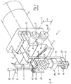
- FIG. 1 represents an entire roller stand 1 with attached drive motor 2 and adjusting means 3 in perspective.
- the roller stand 1 has a fixed bearing block 4 and a U-shaped yoke 5, in each of which the working rollers of two pairs of working rollers 6, 6 'and 7, 7' are mounted.
- the two pairs of work rolls are a pair of beads 7, 7 'and a pair of flanges 6, 6' and have a movable axis 9 in the crosspiece of the yoke 5 and a fixed axis 8 in common.
- the beading roller 7 and the flanging roller 6 are mounted on the same shaft 10 which is coaxial with the axis 8 and which is rotatably mounted in the fixed bearing block 4.
- the bead roller 7 'and the flanging roller 6' are mounted on a shaft 11 which is coaxial with the axis 9 and which is rotatably mounted in the yoke 5.
- the yoke 5 is pivotally mounted on the fixed bearing block 4 with its legs on a pivot pin 12 parallel to the axes 8 and 9.
- a tension rod 13 is connected to the yoke 5 with a bent leg 13 ′, which is approximately parallel to a plane, formed by the axes 8 and 9, in front of the roller stand 1.
- a pressure piston cylinder 14 is articulated on a cantilever part 13 ′′ firmly connected to the pull rod 13, via its piston rod 15 and a tab 16 on a pivot pin 17 arranged on the cantilever part 13 ′′. Furthermore, the pressure piston cylinder 14 is firmly supported by means of a retaining bolt 19 in a side plate 20 fastened to the fixed bearing block 4. In the side plate 20, a shaft 21 is also rotatably mounted, on which an eccentric 22 and an adjusting lever 23 is attached. With the structure shown, there are now two opposing forces. The pressure in the pressure piston cylinder 14, via the piston rod 15, causes a downward pressure force in the position shown, according to arrow 24, which causes the distance X between the axes 8 and 9 to be reduced.
- the adjusting lever 23 is preferably provided with a setting scale (not shown) so that an earlier value can be reset at any time.
- a remotely controllable adjustment drive for example an electric eccentric adjustment, can also be used instead of the manually operated adjustment lever 23.
- Both roller stands 1, 1 'each have opposite pairs of beading rollers 7, 7' or flanging rollers 6, 6 ', in Figure 2 the two beading roller pairs 7, 7' are in use for the simultaneous beading of a sheet 29, for which the Roller stands 1, 1 'are set to a working distance L.
- a bead 30 formed in the process is shown enlarged in FIG. 6B.
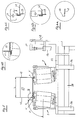
- FIGS. 3 and 4 show how the roller stand 1 is connected to the drive motor 2 via a turntable 31, the turntable 31 being held in a plurality of guide rollers 32 which are arranged on an upright cheek 33 of a sliding table 34.
- the sliding table 34 has a slide 35 which can be moved horizontally together with the roller stand 1.
- a reversing drive 36 which is designed, for example, as a simple pneumatic or hydraulic cylinder and is articulated on the displacement table 34, can now turn the entire roller stand 1 together with the drive motor 2 through an angle of approximately 90 ° (FIG. 5) without the motor Drive interrupted or the distance between the work rolls is changed.
- the drive motor is via a flange 37 2 rigidly connected to the fixed bearing block 4 by screws 38.
- a drive bevel gear 40 Arranged on a drive shaft 39 is a drive bevel gear 40 which, via an overdrive bevel gear 41, drives a shaft 42 arranged at right angles to the drive shaft 39 and a gear 43 rigidly wedged thereon.
- An overdrive spur gear 44 and a gear 45 mesh with the gear 43.
- a gear 46 also meshes with the overdrive gear 44.
- the gear wheels 45 and 46 are each connected in a rotationally fixed manner to one of the shafts 10, 11 and drive the pairs of work rollers 6, 6 'and 7, 7'.
- the whole gear set has a double reduction.
- the two roller stands 1, 1 ' are turned by the turning drive 36 by about 90 ° or by an angle ⁇ , so that the flanging rollers 6, 6' are in use in this position.
- the two roller stands 1, 1' are also set at the desired distance L in FIG. 5 for the flanging operation, so that the sheet 29 is in turn machined on both sides simultaneously can.
- the fold is closed with the flanging rollers 6, 6 'on the sheet metal sides facing away from one another.
- Two sheet metal parts, namely the sheet 29 and a side sheet 47 are closed to form an essentially tight connection. Before the sheet metal parts are closed, several operations are required.
- the side part 47 must first be provided with a side fold 48 according to FIG. 6A. Thereafter, the beads 30 are pressed in on the sheet 29 on both sides, possibly via two to three depth settings, as shown in FIG. 6B.
- FIG. 5 shows a further combination with a stapling device 49, which is actuated by a pressure cylinder 50, a stapling pliers 51.
- the stapling device 49 is attached directly to the machine stand 28, so that the work sequence is possible with the shortest possible travel distance.
- the attachment of the stitching points is shown on a larger scale in FIGS. 6C and 6D.
- the subsequent closing of the fold is shown in FIG. 6E.
- both pairs of work rolls can each be mounted in a pivotable yoke 5 via pivot pins 12 with a correspondingly designed fixed bearing block 4, the setting means 3 being able to be designed essentially in accordance with FIG.
Landscapes
- Engineering & Computer Science (AREA)
- Mechanical Engineering (AREA)
- Bending Of Plates, Rods, And Pipes (AREA)
- Soil Working Implements (AREA)
- Formation And Processing Of Food Products (AREA)
- Metal Rolling (AREA)
Applications Claiming Priority (2)
| Application Number | Priority Date | Filing Date | Title |
|---|---|---|---|
| CH02751/92A CH686662A5 (de) | 1992-09-02 | 1992-09-02 | Blechbearbeitungsmaschine. |
| CH2751/92 | 1992-09-02 |
Publications (2)
| Publication Number | Publication Date |
|---|---|
| EP0585613A1 true EP0585613A1 (fr) | 1994-03-09 |
| EP0585613B1 EP0585613B1 (fr) | 1996-10-02 |
Family
ID=4240790
Family Applications (1)
| Application Number | Title | Priority Date | Filing Date |
|---|---|---|---|
| EP93112222A Expired - Lifetime EP0585613B1 (fr) | 1992-09-02 | 1993-07-30 | Machine à laminer les tÔles |
Country Status (4)
| Country | Link |
|---|---|
| EP (1) | EP0585613B1 (fr) |
| AT (1) | ATE143619T1 (fr) |
| CH (1) | CH686662A5 (fr) |
| DE (1) | DE59304036D1 (fr) |
Cited By (8)
| Publication number | Priority date | Publication date | Assignee | Title |
|---|---|---|---|---|
| EP1518616A3 (fr) * | 2003-09-25 | 2005-04-20 | Mabi Ag | Machine à laminer pour réaliser des nervures, bords et analogues dans des tôles |
| CN104907380A (zh) * | 2015-06-12 | 2015-09-16 | 江阴职业技术学院 | 圆弧板翻边机的传动机构 |
| CN104959484A (zh) * | 2015-06-16 | 2015-10-07 | 上海君屹工业自动化股份有限公司 | 一种汽车轮罩滚边装置 |
| CN106238538A (zh) * | 2016-10-10 | 2016-12-21 | 济南纽兰数控机械有限公司 | 圆弧板翻边机 |
| CN108043929A (zh) * | 2017-12-13 | 2018-05-18 | 潍坊江钢机械有限公司 | 脚踏控制式滚槽机 |
| CN109731960A (zh) * | 2019-01-10 | 2019-05-10 | 凌云工业股份有限公司上海凌云汽车研发分公司 | 汽车用开口保险杠的辊弧装置 |
| CN112845753A (zh) * | 2020-12-22 | 2021-05-28 | 吴宗禹 | 一种自动化铝板成型压边机 |
| CN114378535A (zh) * | 2022-01-13 | 2022-04-22 | 北京城建集团有限责任公司 | 一种管道沟槽连接的施工方法 |
Families Citing this family (1)
| Publication number | Priority date | Publication date | Assignee | Title |
|---|---|---|---|---|
| DE102019129790B4 (de) | 2019-11-05 | 2025-12-04 | Opitz Packaging Systems Gmbh | Verfahren zum automatischen Rillen einer Faltkiste mit eingesetztem Packgut |
Citations (5)
| Publication number | Priority date | Publication date | Assignee | Title |
|---|---|---|---|---|
| DE2549516A1 (de) * | 1975-11-05 | 1977-05-12 | Leifeld & Co | Vielsickenauspressmaschine fuer faesser |
| DE2704633A1 (de) * | 1977-02-04 | 1978-08-10 | Blomberg Werke Kg | Vorrichtung zum falzen eines blechbehaelters |
| US4279211A (en) * | 1979-07-23 | 1981-07-21 | Roll Former Corporation | Controllably driven seamer |
| DE8708142U1 (de) * | 1987-06-09 | 1987-07-30 | Siegwart, Emil, 66299 Friedrichsthal | Falzmaschine für Rohrstücke |
| US4726107A (en) * | 1987-07-06 | 1988-02-23 | Knudson Gary Art | Seaming apparatus |
-
1992
- 1992-09-02 CH CH02751/92A patent/CH686662A5/de not_active IP Right Cessation
-
1993
- 1993-07-30 EP EP93112222A patent/EP0585613B1/fr not_active Expired - Lifetime
- 1993-07-30 AT AT93112222T patent/ATE143619T1/de not_active IP Right Cessation
- 1993-07-30 DE DE59304036T patent/DE59304036D1/de not_active Expired - Lifetime
Patent Citations (5)
| Publication number | Priority date | Publication date | Assignee | Title |
|---|---|---|---|---|
| DE2549516A1 (de) * | 1975-11-05 | 1977-05-12 | Leifeld & Co | Vielsickenauspressmaschine fuer faesser |
| DE2704633A1 (de) * | 1977-02-04 | 1978-08-10 | Blomberg Werke Kg | Vorrichtung zum falzen eines blechbehaelters |
| US4279211A (en) * | 1979-07-23 | 1981-07-21 | Roll Former Corporation | Controllably driven seamer |
| DE8708142U1 (de) * | 1987-06-09 | 1987-07-30 | Siegwart, Emil, 66299 Friedrichsthal | Falzmaschine für Rohrstücke |
| US4726107A (en) * | 1987-07-06 | 1988-02-23 | Knudson Gary Art | Seaming apparatus |
Cited By (9)
| Publication number | Priority date | Publication date | Assignee | Title |
|---|---|---|---|---|
| EP1518616A3 (fr) * | 2003-09-25 | 2005-04-20 | Mabi Ag | Machine à laminer pour réaliser des nervures, bords et analogues dans des tôles |
| EP1724033A3 (fr) * | 2003-09-25 | 2006-11-29 | Mabi Ag | Machine pour réaliser des nervures, bords et analogues dans des tôles |
| CN104907380A (zh) * | 2015-06-12 | 2015-09-16 | 江阴职业技术学院 | 圆弧板翻边机的传动机构 |
| CN104959484A (zh) * | 2015-06-16 | 2015-10-07 | 上海君屹工业自动化股份有限公司 | 一种汽车轮罩滚边装置 |
| CN106238538A (zh) * | 2016-10-10 | 2016-12-21 | 济南纽兰数控机械有限公司 | 圆弧板翻边机 |
| CN108043929A (zh) * | 2017-12-13 | 2018-05-18 | 潍坊江钢机械有限公司 | 脚踏控制式滚槽机 |
| CN109731960A (zh) * | 2019-01-10 | 2019-05-10 | 凌云工业股份有限公司上海凌云汽车研发分公司 | 汽车用开口保险杠的辊弧装置 |
| CN112845753A (zh) * | 2020-12-22 | 2021-05-28 | 吴宗禹 | 一种自动化铝板成型压边机 |
| CN114378535A (zh) * | 2022-01-13 | 2022-04-22 | 北京城建集团有限责任公司 | 一种管道沟槽连接的施工方法 |
Also Published As
| Publication number | Publication date |
|---|---|
| CH686662A5 (de) | 1996-05-31 |
| ATE143619T1 (de) | 1996-10-15 |
| DE59304036D1 (de) | 1996-11-07 |
| EP0585613B1 (fr) | 1996-10-02 |
Similar Documents
| Publication | Publication Date | Title |
|---|---|---|
| DE3544056A1 (de) | Biegemaschine | |
| DE3042383C2 (fr) | ||
| DE69206153T2 (de) | Presse. | |
| EP0585613B1 (fr) | Machine à laminer les tÔles | |
| DE1452946A1 (de) | Glaettwalzvorrichtung | |
| DE1948806A1 (de) | Zahnradwalzvorrichtung | |
| DE2537382A1 (de) | Vorrichtung zum biegen von rohren | |
| DE2232834A1 (de) | Maschine zum automatischen abschneiden von rohrstuecken von einem kontinuierlich vorbewegten rohr | |
| DE20104582U1 (de) | Dreiwalzen-Biegewerkzeug | |
| WO1992000154A1 (fr) | Machine a plier et a former des feuilles de tole | |
| DE69509936T2 (de) | Blechbiegemaschine | |
| EP1490186A1 (fr) | Cintreuse destinee a de profiles et des tuyaux ronds | |
| EP0497780B1 (fr) | Procede de cintrage oppose d'une tole | |
| DE102009024523A1 (de) | Bandsägemaschine mit einem Sägerahmen mit Sägeband | |
| EP2145706B1 (fr) | Dispositif de dressage de marchandises métalliques | |
| DE2017557A1 (de) | Streckmaschine zum Streckziehen und -richten von Metallblechen und -platten | |
| DE19853294A1 (de) | Vorrichtung zum Streckbiegen von Metallstäben oder -profilen | |
| DE1627586A1 (de) | Rollenbiegemaschine | |
| DE3342189C2 (fr) | ||
| DE2409833C3 (de) | Kettenschweißmaschine | |
| DE2334436A1 (de) | Vier-walzen-blechbiegemaschine | |
| DE2419231B2 (de) | Vorrichtung zum schrittweisen Gittertransport um unterschiedliche Beträge bei einer Gitterschweißmaschine | |
| DE909564C (de) | Maschine zum Biegen von duennwandigen offenen Metallprofilen | |
| DE2714652A1 (de) | Siebdruckvorrichtung | |
| DE2252467C3 (fr) |
Legal Events
| Date | Code | Title | Description |
|---|---|---|---|
| PUAI | Public reference made under article 153(3) epc to a published international application that has entered the european phase |
Free format text: ORIGINAL CODE: 0009012 |
|
| AK | Designated contracting states |
Kind code of ref document: A1 Designated state(s): AT BE DE DK FR IT NL |
|
| 17P | Request for examination filed |
Effective date: 19940825 |
|
| 17Q | First examination report despatched |
Effective date: 19950327 |
|
| GRAH | Despatch of communication of intention to grant a patent |
Free format text: ORIGINAL CODE: EPIDOS IGRA |
|
| GRAH | Despatch of communication of intention to grant a patent |
Free format text: ORIGINAL CODE: EPIDOS IGRA |
|
| GRAA | (expected) grant |
Free format text: ORIGINAL CODE: 0009210 |
|
| AK | Designated contracting states |
Kind code of ref document: B1 Designated state(s): AT BE DE DK FR IT NL |
|
| PG25 | Lapsed in a contracting state [announced via postgrant information from national office to epo] |
Ref country code: NL Free format text: LAPSE BECAUSE OF FAILURE TO SUBMIT A TRANSLATION OF THE DESCRIPTION OR TO PAY THE FEE WITHIN THE PRESCRIBED TIME-LIMIT Effective date: 19961002 Ref country code: DK Effective date: 19961002 |
|
| REF | Corresponds to: |
Ref document number: 143619 Country of ref document: AT Date of ref document: 19961015 Kind code of ref document: T |
|
| REF | Corresponds to: |
Ref document number: 59304036 Country of ref document: DE Date of ref document: 19961107 |
|
| ITF | It: translation for a ep patent filed | ||
| ET | Fr: translation filed | ||
| NLV1 | Nl: lapsed or annulled due to failure to fulfill the requirements of art. 29p and 29m of the patents act | ||
| PG25 | Lapsed in a contracting state [announced via postgrant information from national office to epo] |
Ref country code: AT Free format text: LAPSE BECAUSE OF NON-PAYMENT OF DUE FEES Effective date: 19970730 |
|
| PG25 | Lapsed in a contracting state [announced via postgrant information from national office to epo] |
Ref country code: BE Effective date: 19970731 |
|
| PLBE | No opposition filed within time limit |
Free format text: ORIGINAL CODE: 0009261 |
|
| 26N | No opposition filed | ||
| BERE | Be: lapsed |
Owner name: MABI A.G. ISOLIERMASCHINEN Effective date: 19970731 |
|
| PGFP | Annual fee paid to national office [announced via postgrant information from national office to epo] |
Ref country code: IT Payment date: 20120727 Year of fee payment: 20 Ref country code: FR Payment date: 20120806 Year of fee payment: 20 Ref country code: DE Payment date: 20120720 Year of fee payment: 20 |
|
| REG | Reference to a national code |
Ref country code: DE Ref legal event code: R071 Ref document number: 59304036 Country of ref document: DE |
|
| PG25 | Lapsed in a contracting state [announced via postgrant information from national office to epo] |
Ref country code: DE Free format text: LAPSE BECAUSE OF EXPIRATION OF PROTECTION Effective date: 20130731 |