EP0585633A1 - Verriegelbare elektrische Steckkupplung - Google Patents
Verriegelbare elektrische Steckkupplung Download PDFInfo
- Publication number
- EP0585633A1 EP0585633A1 EP93112397A EP93112397A EP0585633A1 EP 0585633 A1 EP0585633 A1 EP 0585633A1 EP 93112397 A EP93112397 A EP 93112397A EP 93112397 A EP93112397 A EP 93112397A EP 0585633 A1 EP0585633 A1 EP 0585633A1
- Authority
- EP
- European Patent Office
- Prior art keywords
- latch
- connector
- unlatching
- connectors
- electrical connector
- Prior art date
- Legal status (The legal status is an assumption and is not a legal conclusion. Google has not performed a legal analysis and makes no representation as to the accuracy of the status listed.)
- Granted
Links
Images


Classifications
-
- H—ELECTRICITY
- H01—ELECTRIC ELEMENTS
- H01R—ELECTRICALLY-CONDUCTIVE CONNECTIONS; STRUCTURAL ASSOCIATIONS OF A PLURALITY OF MUTUALLY-INSULATED ELECTRICAL CONNECTING ELEMENTS; COUPLING DEVICES; CURRENT COLLECTORS
- H01R13/00—Details of coupling devices of the kinds covered by groups H01R12/70 or H01R24/00 - H01R33/00
- H01R13/62—Means for facilitating engagement or disengagement of coupling parts or for holding them in engagement
- H01R13/639—Additional means for holding or locking coupling parts together, after engagement, e.g. separate keylock, retainer strap
-
- H—ELECTRICITY
- H01—ELECTRIC ELEMENTS
- H01R—ELECTRICALLY-CONDUCTIVE CONNECTIONS; STRUCTURAL ASSOCIATIONS OF A PLURALITY OF MUTUALLY-INSULATED ELECTRICAL CONNECTING ELEMENTS; COUPLING DEVICES; CURRENT COLLECTORS
- H01R13/00—Details of coupling devices of the kinds covered by groups H01R12/70 or H01R24/00 - H01R33/00
- H01R13/62—Means for facilitating engagement or disengagement of coupling parts or for holding them in engagement
- H01R13/627—Snap or like fastening
- H01R13/6271—Latching means integral with the housing
-
- H—ELECTRICITY
- H01—ELECTRIC ELEMENTS
- H01R—ELECTRICALLY-CONDUCTIVE CONNECTIONS; STRUCTURAL ASSOCIATIONS OF A PLURALITY OF MUTUALLY-INSULATED ELECTRICAL CONNECTING ELEMENTS; COUPLING DEVICES; CURRENT COLLECTORS
- H01R13/00—Details of coupling devices of the kinds covered by groups H01R12/70 or H01R24/00 - H01R33/00
- H01R13/62—Means for facilitating engagement or disengagement of coupling parts or for holding them in engagement
- H01R13/627—Snap or like fastening
-
- H—ELECTRICITY
- H01—ELECTRIC ELEMENTS
- H01R—ELECTRICALLY-CONDUCTIVE CONNECTIONS; STRUCTURAL ASSOCIATIONS OF A PLURALITY OF MUTUALLY-INSULATED ELECTRICAL CONNECTING ELEMENTS; COUPLING DEVICES; CURRENT COLLECTORS
- H01R13/00—Details of coupling devices of the kinds covered by groups H01R12/70 or H01R24/00 - H01R33/00
- H01R13/62—Means for facilitating engagement or disengagement of coupling parts or for holding them in engagement
- H01R13/629—Additional means for facilitating engagement or disengagement of coupling parts, e.g. aligning or guiding means, levers, gas pressure electrical locking indicators, manufacturing tolerances
- H01R13/633—Additional means for facilitating engagement or disengagement of coupling parts, e.g. aligning or guiding means, levers, gas pressure electrical locking indicators, manufacturing tolerances for disengagement only
Definitions
- This invention generally relates to the art of electrical connectors and, particularly, to a latchable electrical connector system having improved means for unlatching a pair of mating connectors.
- latching devices are designed simply to hold the connectors in mated condition but to allow the connectors to be readily unmated.
- latching devices are designed to prevent unmating of the connectors unless the latching devices, themselves, are physically unlatched. In the latter applications, unlatching of the connectors can be very difficult or cumbersome because of the design of the latching devices or because of the small dimensions of the connectors which render manual manipulation very difficult. In fact, some latching/unlatching mechanisms require a user to physically hold a connector with one hand while unlatching the latch mechanism(s) with the other hand.
- latching systems for electrical connectors. Many such systems utilize flexible or resilient latch arms, cam latches on flexible walls of a connector, or the like, all of which operate on a sort of resilient snap-lock action. In other words, a pair of electrical connectors will be automatically latched upon mating, and the latching device therefore must be unlatched or released in order to unmate the connectors. If a latching device snaps into a latched position upon mating of the connectors, the latching device must be moved out of its latched condition before the connectors can be unmated. Problems constantly are encountered in effecting unlatching and unmating of the connectors because of unnecessary manual manipulations required.
- Latching mechanisms also are prone to cause other problems in the design of electrical connectors. For instance, latching devices often create projections which interfere with or trap extraneous objects, such as electrical wires. Latch arms often are prone to breakage, because the arms often are integrally molded with an electrical connector housing.
- This invention is directed to a latchable electrical connector system which solves the above and other problems in many previous latching devices by affording a simple one-hand unlatching action in a mechanism which prevents entanglement of the latching devices with wires or other extraneous objects and which is not prone to breakage.
- An object, therefore, of the invention is to provide a new and improved unlatching means in a latchable electrical connector system.
- first and second electrical connectors are mateable in a given mating direction.
- the first connector includes a pair of latch devices interengageable with complementary latch means on the second connector when the connectors are mated to resist unmating of the connectors.
- the latch devices are flexible in a direction transverse to the mating direction for movement into and out of latching interengagement with the latch means of the second connector.
- the invention contemplates the provision of transversely flexible unlatching means coupled between the latch devices and bowed outwardly therefrom whereby inward flexing of the unlatching means, as by the application of pressure by a user, is effective to cause outward unlatching movement of the latch devices.
- the invention is disclosed herein in combination with an electrical connector which includes a molded dielectric housing including the latch devices.
- the unlatching means are integrally molded between the latch devices.
- the latch devices are formed on a pair of opposite side walls of a connector housing.
- the unlatching means comprise a flexible band joining the side walls in an outwardly bowed configuration.
- the flexible band extends approximately 180° about the connector in an outwardly bowed configuration.
- the latch devices are formed by flexible cantilevered latch arms extending axially of the connector.
- the unlatching means are provided by a flexible ring-like member extending 360° about the connector, spaced outwardly therefrom and joining the cantilevered latch arms.
- the latch arms include latch hooks near the distal ends thereof, and the ring-like member joins the distal ends of the cantilevered latch arms.
- male connector 10 mateable with a female connector, generally designated 12.
- the connectors are mateable and unmateable in a given mating direction, as indicated by double-headed arrow "A".
- Male connector 10 includes a dielectric housing 14 of a generally rectangular configuration and includes a pair of side walls 16.
- the housing mounts appropriate terminals (not shown) terminated therein to appropriate electrical wires 18.
- Housing 14 is unitarily molded of dielectric material, such as plastic or the like, and includes a latch boss 20 projecting outwardly from each side wall 16.
- Each latch boss includes a forwardly facing ramp or cam surface 20a.
- Female connector 20 also includes a dielectric housing, generally designated 22, which is unitarily molded of dielectric material, such as plastic or the like.
- the housing mounts appropriate terminals therewithin, the terminals being terminated to appropriate electrical wires 24.
- the terminals may be socket contacts 26 for receiving pin contacts recessed within housing 14 of male connector 10.
- the unitarily molded housing 22 of female connector 12 includes a top wall 28, a bottom wall 30 and a pair of side walls 32 which cooperate to form a generally rectangular female recess for receiving housing 14 of male connector 10.
- housing 22 of female connector 12 includes a pair of latch devices 34 projecting inwardly from side wall 32.
- the latch devices are designed for riding over ramp surfaces 20a of latch bosses 20 of male connector housing 14 and to snap-lock behind the bosses when connectors 10 and 12 are fully mated.
- side walls 32 are spaced from side edges of top wall 28, as at 36, and openings or windows 38 are provided in the side walls so that flexibility or resiliency is provided for latch devices 34 whereby the latch devices and the surrounding wall portions can yield or flex outwardly (i.e. transversely of mating direction "A") upon mating of the connectors, with the latch devices automatically snapping into locked condition behind latch bosses 20 of male connector 10.
- the invention contemplates an improved unlatching means for unlatching the connectors by a user with a single hand manipulating female connector 12 while male connector 10 either is stationary or held with the user's other hand. More particularly, a transversely flexible band 40 is bowed outwardly of the connector and is coupled to or joined with latch devices 34, by integrally molding the unlatching band with the unitarily molded dielectric housing of female connector 12.
- Figures 1 and 3 show unlatching band 40 in its normal or unstressed state, i.e. in an outwardly bowed configuration relative to the connector.
- Figure 2 shows how the unlatching band projects upwardly from the connector in its unstressed state.
- inward pressure is applied to unlatching band 40 in the direction of arrows "B".
- This can be done by manual manipulation by a user simply by pinching the connector between the user's fingers on top of the band and on the bottom of the connector housing.
- the connector can be unlatched and unmated with the same manual manipulatable action of pinching and pulling on the connector.
- FIG 4 shows unlatching band 40 having been depressed in the direction of arrow "B", and a comparison can be made between the depressed unlatching condition of band 40 in Figure 4 with the outwardly bowed unstressed state of the band in Figure 3.
- latch devices 34 When the band is depressed (or compressed toward the connector housing) as viewed in Figure 4, it can be seen that latch devices 34 have been forced outwardly in the direction of arrows "C". By this action, the latch devices have been moved transversely outwardly from their locked condition behind latch bosses 20 of male connector 10, and the male and female connectors can be readily unmated.
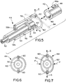
- FIG. 5 shows the invention incorporated in a second embodiment of the invention which includes a female connector, generally designated 42, and a male connector, generally designated 44.
- Female connector 42 is shown simply as a cylindrical housing defining a receptacle 46. Similar to latch bosses 20 of male connector 10 in Figure 1, female connector 42 includes a pair of latch bosses 48 having forwardly facing cam or ramp surfaces 48a. The latch bosses project transversely outwardly from opposite diametral sides of the female connector.
- Connectors 42 and 44 are mated and unmated in the direction of double-headed arrow "D".
- Male connector 44 includes a cylindrical housing 50 mounting appropriate terminals therewithin for termination to an electrical cable 52.
- a forward mating end 54 of the connector is sized for insertion into receptacle 46 of female connector 42.
- a pair of seal rings 46 may be provided for sealing between the forward mating portion and the inside of the receptacle.
- Male connector 44 is provided with latch means in the form of a pair of forwardly projecting flexible cantilevered latch arms 58 unitarily molded at their proximal ends 58a to housing 50 and defining latch hook portions 60 at their distal ends.
- latch means in the form of a pair of forwardly projecting flexible cantilevered latch arms 58 unitarily molded at their proximal ends 58a to housing 50 and defining latch hook portions 60 at their distal ends.
- the unlatching means of the embodiment of the invention shown in Figure 5 is provided by a flexible ring-like unlatching member 62 coupled between or joining cantilevered latch arms 58 at their distal ends, i.e. joining the hook portions 60 of the respective latch arms.
- Flexible ring 62 can be molded integrally with and between the distal ends of the latch arms, or the ring could be provided by a separate flexible plastic component running through appropriate holes in the distal ends of the latch arms. Regardless, the unlatching ring is transversely flexible relative to the mating direction of the connectors as indicated by double-headed arrow "D".
- Figure 6 shows the outwardly bowed configuration of unlatching ring 62, i.e. in its natural or unstressed state. This is the configuration of the latch ring when hook portions 60 of latch arms 58 are snap-locked behind latch bosses 48 of female connector 42.
- Unlatching ring 62 in the embodiment of Figures 5-7 also affords other advantages. As stated in the "Background", above, many electrical connectors utilize cantilevered latch arms as their latching mechanisms. These arms are prone to become broken or bent. Ring 62 prevents the latch arms from being outwardly overstressed (which would lose their flexibility) and also prevents the latch arms from being completely broken away from the male connector. Still further, and referring to Figure 5, extraneous objects, such as a wire 64, are prone to become entangled or trapped behind latch arms of connectors heretofore available. Ring 62 prevents extraneous objects from riding under the latch arms.
Landscapes
- Details Of Connecting Devices For Male And Female Coupling (AREA)
Applications Claiming Priority (2)
| Application Number | Priority Date | Filing Date | Title |
|---|---|---|---|
| US07/929,610 US5314347A (en) | 1992-08-13 | 1992-08-13 | Latchable electrical connector system |
| US929610 | 1992-08-13 |
Publications (2)
| Publication Number | Publication Date |
|---|---|
| EP0585633A1 true EP0585633A1 (de) | 1994-03-09 |
| EP0585633B1 EP0585633B1 (de) | 1998-02-25 |
Family
ID=25458148
Family Applications (1)
| Application Number | Title | Priority Date | Filing Date |
|---|---|---|---|
| EP93112397A Expired - Lifetime EP0585633B1 (de) | 1992-08-13 | 1993-08-03 | Verriegelbare elektrische Steckkupplung |
Country Status (5)
| Country | Link |
|---|---|
| US (1) | US5314347A (de) |
| EP (1) | EP0585633B1 (de) |
| JP (1) | JP2622935B2 (de) |
| KR (1) | KR970003360B1 (de) |
| DE (1) | DE69317082T2 (de) |
Cited By (8)
| Publication number | Priority date | Publication date | Assignee | Title |
|---|---|---|---|---|
| FR2717628A1 (fr) * | 1994-03-21 | 1995-09-22 | Cinch Connecteurs Sa | Connecteur électrique. |
| FR2717623A1 (fr) * | 1994-03-15 | 1995-09-22 | Pizon Ernest | Connecteur pour câble coaxial. |
| WO1996009666A1 (en) * | 1994-09-22 | 1996-03-28 | The Whitaker Corporation | Overmold strain relief and snag prevention feature |
| FR2731116A1 (fr) * | 1995-02-23 | 1996-08-30 | Bosch Gmbh Robert | Connecteur electrique dont le dispositif d'encliquetage presente au moins un element elastique |
| GB2344700A (en) * | 1998-12-09 | 2000-06-14 | Ibm | Releasing latched connectors |
| EP2233171A1 (de) * | 2006-09-21 | 2010-09-29 | Covidien AG | Sicherheitssteckeranordnung |
| WO2012007180A1 (de) * | 2010-07-16 | 2012-01-19 | Phoenix Contact Gmbh & Co. Kg | Gehäuse, insbesondere für einen elektrischen kabelanschluss |
| US8257287B2 (en) | 2008-03-20 | 2012-09-04 | Tyco Healthcare Group Lp | Safety connector assembly |
Families Citing this family (24)
| Publication number | Priority date | Publication date | Assignee | Title |
|---|---|---|---|---|
| US5558534A (en) * | 1994-06-30 | 1996-09-24 | The Whitaker Corporation | Self sacrificing latching system |
| US5449298A (en) * | 1994-06-30 | 1995-09-12 | The Whitaker Corporation | Latching system for intermatable connectors |
| US5547388A (en) * | 1994-09-13 | 1996-08-20 | Yazaki Corporation | Connector cover having a squeeze release |
| US6755676B2 (en) | 1995-07-07 | 2004-06-29 | Henry Milan | Modular outlet strip |
| US5569047A (en) * | 1995-08-31 | 1996-10-29 | The Whitaker Corporation | Latching system for intermatable transmission connectors |
| DE19611965B4 (de) * | 1996-03-26 | 2006-09-07 | The Whitaker Corp., Wilmington | Anordnung zur Verriegelung eines elektrischen Steckverbinders |
| DE19620177A1 (de) * | 1996-05-20 | 1997-11-27 | Amp Holland | Elektrischer Stecker bestehend aus zwei Steckerhälften |
| DE19721977A1 (de) * | 1997-05-26 | 1998-12-03 | Amp Gmbh | Anordnung zur Verrastung und Verriegelung zweier komplementärer Verbinderstrukturen |
| DE19944895C2 (de) * | 1999-09-09 | 2002-01-31 | Infineon Technologies Ag | Optischer Steckverbinder |
| US6716065B1 (en) | 2000-06-01 | 2004-04-06 | Leftek International, Llc | Electrical systems with paired bus connectors |
| US6482040B1 (en) | 2000-06-01 | 2002-11-19 | Dennis L. Brooks | Electrical systems using linear fusing |
| US6943661B2 (en) | 2001-10-16 | 2005-09-13 | General Electric Company | Quick-connect positive temperature coefficient of resistance resistor/overload assembly and method |
| JP2003297482A (ja) * | 2002-02-01 | 2003-10-17 | Japan Aviation Electronics Industry Ltd | プルタブを用いたロック解除機構及びコネクタ |
| US6832921B1 (en) * | 2004-02-02 | 2004-12-21 | Darren Stewart | Electrical safety outlet and power cord |
| CA2550527A1 (en) * | 2005-06-21 | 2006-12-21 | Ideal Industries, Inc. | Electrical disconnect with push-in connectors |
| US7527509B1 (en) * | 2005-06-21 | 2009-05-05 | Ideal Industries, Inc. | Electrical disconnect with push-in connectors |
| US7727002B2 (en) * | 2006-06-21 | 2010-06-01 | Ideal Industries, Inc. | Electrical disconnect with adjacent wire receptacle boxes |
| US7241186B1 (en) * | 2006-09-18 | 2007-07-10 | Yu-Chu Lin | Vehicle lighting source adapter |
| EP2302744B1 (de) * | 2009-09-24 | 2012-06-20 | Tyco Electronics France SAS | Steckerbuchse mit Stützelement, Stecker mit Verformungstasche und Steckereinheit mit mindestens einer Buchse und einem Stecker sowie Verfahren zum Verbinden eines Steckers und einer Buchse |
| US9054449B2 (en) * | 2012-01-27 | 2015-06-09 | Chatsworth Products, Inc. | Cable retention system for power distribution unit |
| US10944155B2 (en) * | 2015-01-13 | 2021-03-09 | Commscope Technologies Llc | Standard antenna interface connector assembly |
| DE102017125915B4 (de) * | 2017-11-07 | 2026-01-29 | Phoenix Contact Gmbh & Co. Kg | Verriegelung für Steckverbinder |
| JP7391380B2 (ja) * | 2018-04-27 | 2023-12-05 | 伊東電機株式会社 | コネクタ構造、コネクタ、並びに、コネクタ係合片 |
| KR102234247B1 (ko) * | 2018-08-29 | 2021-04-02 | 앱티브 테크놀러지스 리미티드 | 커넥터 및 이를 포함하는 커넥터 조립체 |
Citations (4)
| Publication number | Priority date | Publication date | Assignee | Title |
|---|---|---|---|---|
| US3639950A (en) * | 1968-09-13 | 1972-02-08 | Itt | Latching device |
| GB2113482A (en) * | 1982-01-11 | 1983-08-03 | Bard Inc C R | Electrical connectors |
| DE3237093A1 (de) * | 1982-10-07 | 1984-04-12 | Dr.Ing.H.C. F. Porsche Ag, 7000 Stuttgart | Elektrische steckvorrichtung |
| DE4119122A1 (de) * | 1991-06-10 | 1992-12-17 | Bosch Gmbh Robert | Elektrische steckverbindung |
Family Cites Families (6)
| Publication number | Priority date | Publication date | Assignee | Title |
|---|---|---|---|---|
| US4284313A (en) * | 1979-10-17 | 1981-08-18 | International Telephone And Telegraph Corporation | Quick detachable electrical connector |
| AU544160B2 (en) * | 1981-03-18 | 1985-05-16 | Amp Incorporated | Electrical connector assembly |
| US4441776A (en) * | 1981-11-09 | 1984-04-10 | Itt Corporation | Quick detachable coupling |
| US5059140A (en) * | 1984-01-16 | 1991-10-22 | Stewart Stamping Corporation | Shielded plug and jack connector |
| US4986766A (en) * | 1988-08-17 | 1991-01-22 | Molex Incorporated | Electrical connector having anti-overstress latch |
| JP2561960B2 (ja) * | 1989-07-18 | 1996-12-11 | 矢崎総業株式会社 | 電気コネクタの嵌合確認装置 |
-
1992
- 1992-08-13 US US07/929,610 patent/US5314347A/en not_active Expired - Fee Related
-
1993
- 1993-07-29 KR KR1019930014509A patent/KR970003360B1/ko not_active Expired - Fee Related
- 1993-07-29 JP JP5207303A patent/JP2622935B2/ja not_active Expired - Lifetime
- 1993-08-03 EP EP93112397A patent/EP0585633B1/de not_active Expired - Lifetime
- 1993-08-03 DE DE69317082T patent/DE69317082T2/de not_active Expired - Fee Related
Patent Citations (4)
| Publication number | Priority date | Publication date | Assignee | Title |
|---|---|---|---|---|
| US3639950A (en) * | 1968-09-13 | 1972-02-08 | Itt | Latching device |
| GB2113482A (en) * | 1982-01-11 | 1983-08-03 | Bard Inc C R | Electrical connectors |
| DE3237093A1 (de) * | 1982-10-07 | 1984-04-12 | Dr.Ing.H.C. F. Porsche Ag, 7000 Stuttgart | Elektrische steckvorrichtung |
| DE4119122A1 (de) * | 1991-06-10 | 1992-12-17 | Bosch Gmbh Robert | Elektrische steckverbindung |
Cited By (18)
| Publication number | Priority date | Publication date | Assignee | Title |
|---|---|---|---|---|
| FR2717623A1 (fr) * | 1994-03-15 | 1995-09-22 | Pizon Ernest | Connecteur pour câble coaxial. |
| US5620330A (en) * | 1994-03-15 | 1997-04-15 | Mecaniplast | Connector for coaxial cable |
| FR2717628A1 (fr) * | 1994-03-21 | 1995-09-22 | Cinch Connecteurs Sa | Connecteur électrique. |
| WO1996009666A1 (en) * | 1994-09-22 | 1996-03-28 | The Whitaker Corporation | Overmold strain relief and snag prevention feature |
| US5600885A (en) * | 1994-09-22 | 1997-02-11 | The Whitaker Corporation | Method of fabricating an overmold onto an electrical cable assembly terminated to a cable |
| FR2731116A1 (fr) * | 1995-02-23 | 1996-08-30 | Bosch Gmbh Robert | Connecteur electrique dont le dispositif d'encliquetage presente au moins un element elastique |
| GB2344700A (en) * | 1998-12-09 | 2000-06-14 | Ibm | Releasing latched connectors |
| US6146179A (en) * | 1998-12-09 | 2000-11-14 | International Business Machines Corporation | Auto unlatching connector tab |
| EP2233171A1 (de) * | 2006-09-21 | 2010-09-29 | Covidien AG | Sicherheitssteckeranordnung |
| US8257286B2 (en) | 2006-09-21 | 2012-09-04 | Tyco Healthcare Group Lp | Safety connector apparatus |
| US8287517B2 (en) | 2006-09-21 | 2012-10-16 | Tyco Healtcare Group Lp | Safety connector assembly |
| US9687249B2 (en) | 2006-09-21 | 2017-06-27 | Covidien Lp | Safety connector assembly |
| US8257287B2 (en) | 2008-03-20 | 2012-09-04 | Tyco Healthcare Group Lp | Safety connector assembly |
| WO2012007180A1 (de) * | 2010-07-16 | 2012-01-19 | Phoenix Contact Gmbh & Co. Kg | Gehäuse, insbesondere für einen elektrischen kabelanschluss |
| DE102010027524A1 (de) * | 2010-07-16 | 2012-01-19 | Phoenix Contact Gmbh & Co. Kg | Gehäuse, insbesondere für einen elektrischen Kabelanschluss |
| CN103026558A (zh) * | 2010-07-16 | 2013-04-03 | 菲尼克斯电气公司 | 具体用于电气线缆连接器的壳体 |
| US9011171B2 (en) | 2010-07-16 | 2015-04-21 | Phoenix Contact Gmbh & Co. Kg | Housing, in particular for an electrical cable connection |
| CN103026558B (zh) * | 2010-07-16 | 2016-02-10 | 菲尼克斯电气公司 | 具体用于电气线缆连接器的壳体 |
Also Published As
| Publication number | Publication date |
|---|---|
| JPH07307184A (ja) | 1995-11-21 |
| KR970003360B1 (ko) | 1997-03-17 |
| DE69317082D1 (de) | 1998-04-02 |
| US5314347A (en) | 1994-05-24 |
| KR940004890A (ko) | 1994-03-16 |
| EP0585633B1 (de) | 1998-02-25 |
| JP2622935B2 (ja) | 1997-06-25 |
| DE69317082T2 (de) | 1998-11-05 |
Similar Documents
| Publication | Publication Date | Title |
|---|---|---|
| US5314347A (en) | Latchable electrical connector system | |
| US4657331A (en) | Strain relief for electrical connector assemblies | |
| US6045388A (en) | Electrical connector position assurance system | |
| EP0729202B1 (de) | Verriegelungsmechanismus für Verbindergehäuse | |
| US4776813A (en) | Sealed connector assembly | |
| EP0697754B1 (de) | Elektrische Verbindereinheit mit einer Verriegelungsanordnung | |
| US4571017A (en) | Electrical connector assembly | |
| JP2888925B2 (ja) | ラッチ手段を具備したコネクタ構造 | |
| US4431244A (en) | Electrical connector with integral latch | |
| US6017233A (en) | Floating panel mount system for electrical connectors | |
| US5902155A (en) | Electrical connector assembly | |
| US5688142A (en) | Eletrical connector position assurance system | |
| US5211572A (en) | Security locking key mechanism for electrical connectors | |
| US6398577B1 (en) | Latching/unlatching system for electrical connectors | |
| EP1067635A2 (de) | Elektrische Verbinderanordnung mit einem Führungszapfenverriegelungssystem | |
| US5273453A (en) | Electrical connector with positive latch | |
| US5525072A (en) | Electrical connector assembly for interconnecting a flat cable to a circuit board | |
| US4441776A (en) | Quick detachable coupling | |
| US5545054A (en) | Electrical connector with hinged cover | |
| EP0665453B1 (de) | Elektrische Steckeranordnung | |
| US6527450B1 (en) | Latching system for connector assemblies | |
| US7081003B1 (en) | Electrical connector with improved latching system | |
| US6540542B1 (en) | Electrical connector with improved latch means | |
| US4647128A (en) | Electrical connector system with releasable latching | |
| EP0508196A2 (de) | Elektrischer Starkstromsteckverbinder |
Legal Events
| Date | Code | Title | Description |
|---|---|---|---|
| PUAI | Public reference made under article 153(3) epc to a published international application that has entered the european phase |
Free format text: ORIGINAL CODE: 0009012 |
|
| AK | Designated contracting states |
Kind code of ref document: A1 Designated state(s): DE FR GB IT |
|
| 17P | Request for examination filed |
Effective date: 19940816 |
|
| 17Q | First examination report despatched |
Effective date: 19941118 |
|
| GRAG | Despatch of communication of intention to grant |
Free format text: ORIGINAL CODE: EPIDOS AGRA |
|
| GRAG | Despatch of communication of intention to grant |
Free format text: ORIGINAL CODE: EPIDOS AGRA |
|
| GRAH | Despatch of communication of intention to grant a patent |
Free format text: ORIGINAL CODE: EPIDOS IGRA |
|
| ITF | It: translation for a ep patent filed | ||
| GRAH | Despatch of communication of intention to grant a patent |
Free format text: ORIGINAL CODE: EPIDOS IGRA |
|
| GRAA | (expected) grant |
Free format text: ORIGINAL CODE: 0009210 |
|
| AK | Designated contracting states |
Kind code of ref document: B1 Designated state(s): DE FR GB IT |
|
| REF | Corresponds to: |
Ref document number: 69317082 Country of ref document: DE Date of ref document: 19980402 |
|
| ET | Fr: translation filed | ||
| PLBE | No opposition filed within time limit |
Free format text: ORIGINAL CODE: 0009261 |
|
| 26N | No opposition filed | ||
| PGFP | Annual fee paid to national office [announced via postgrant information from national office to epo] |
Ref country code: GB Payment date: 20000703 Year of fee payment: 8 |
|
| PGFP | Annual fee paid to national office [announced via postgrant information from national office to epo] |
Ref country code: FR Payment date: 20000803 Year of fee payment: 8 |
|
| PGFP | Annual fee paid to national office [announced via postgrant information from national office to epo] |
Ref country code: DE Payment date: 20000830 Year of fee payment: 8 |
|
| PG25 | Lapsed in a contracting state [announced via postgrant information from national office to epo] |
Ref country code: GB Free format text: LAPSE BECAUSE OF NON-PAYMENT OF DUE FEES Effective date: 20010803 |
|
| GBPC | Gb: european patent ceased through non-payment of renewal fee |
Effective date: 20010803 |
|
| PG25 | Lapsed in a contracting state [announced via postgrant information from national office to epo] |
Ref country code: FR Free format text: LAPSE BECAUSE OF NON-PAYMENT OF DUE FEES Effective date: 20020430 |
|
| PG25 | Lapsed in a contracting state [announced via postgrant information from national office to epo] |
Ref country code: DE Free format text: LAPSE BECAUSE OF NON-PAYMENT OF DUE FEES Effective date: 20020501 |
|
| REG | Reference to a national code |
Ref country code: FR Ref legal event code: ST |
|
| PG25 | Lapsed in a contracting state [announced via postgrant information from national office to epo] |
Ref country code: IT Free format text: LAPSE BECAUSE OF NON-PAYMENT OF DUE FEES;WARNING: LAPSES OF ITALIAN PATENTS WITH EFFECTIVE DATE BEFORE 2007 MAY HAVE OCCURRED AT ANY TIME BEFORE 2007. THE CORRECT EFFECTIVE DATE MAY BE DIFFERENT FROM THE ONE RECORDED. Effective date: 20050803 |