EP0585637B1 - Disque d'épandage de matériau avec aubes enlevables - Google Patents
Disque d'épandage de matériau avec aubes enlevables Download PDFInfo
- Publication number
- EP0585637B1 EP0585637B1 EP19930112417 EP93112417A EP0585637B1 EP 0585637 B1 EP0585637 B1 EP 0585637B1 EP 19930112417 EP19930112417 EP 19930112417 EP 93112417 A EP93112417 A EP 93112417A EP 0585637 B1 EP0585637 B1 EP 0585637B1
- Authority
- EP
- European Patent Office
- Prior art keywords
- spreader
- carrier disc
- disc
- vane
- pressure
- Prior art date
- Legal status (The legal status is an assumption and is not a legal conclusion. Google has not performed a legal analysis and makes no representation as to the accuracy of the status listed.)
- Expired - Lifetime
Links
Images


Classifications
-
- A—HUMAN NECESSITIES
- A01—AGRICULTURE; FORESTRY; ANIMAL HUSBANDRY; HUNTING; TRAPPING; FISHING
- A01C—PLANTING; SOWING; FERTILISING
- A01C17/00—Fertilisers or seeders with centrifugal wheels
- A01C17/006—Regulating or dosing devices
- A01C17/008—Devices controlling the quantity or the distribution pattern
-
- A—HUMAN NECESSITIES
- A01—AGRICULTURE; FORESTRY; ANIMAL HUSBANDRY; HUNTING; TRAPPING; FISHING
- A01C—PLANTING; SOWING; FERTILISING
- A01C17/00—Fertilisers or seeders with centrifugal wheels
- A01C17/001—Centrifugal throwing devices with a vertical axis
Definitions
- the present invention relates to a rotating spreader disc for spreading flowable material, said spreader disc being of the kind set forth in the preamble of claim 1.
- a spreader disc of the kind referred to above is known from the German published specification No. DE-A-3.919.396, see especially Figures 5-7 with the associated text.
- the securing member consists of a bolt with an attached wing nut, said wing nut to be loosened or tightened respectively, when the vane is to be removed or secured respectively.
- This known arrangement suffers from three substantial disadvantages, viz.
- over-centre mechanisms for easy securing and easy freeing of attachments.
- over-centre mechanism is disclosed in FR-A-2,659,400, and other well-known uses are ski bindings and closures for jars used in households for preserving foods, as well as quick-coupling arrangements of various kinds.
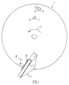
- the spreader disc shown diagrammatically in Figure 1 consists in a manner known in principle of a plane or disc-shaped carrier disc 1, to which a number of spreader vanes 2 - in the present example two - of which only one is shown, is secured in a detachable and adjustable manner.
- the carrier disc 1 is intended to rotate in the direction shown by an arrow 3, thus spreading flowable solid material, e.g. artificial fertilizer, from above falling down on to the generally horizontal carrier disc 1, and by the latter and by the spreader vanes 2 being spread outwardly laterally.
- flowable solid material e.g. artificial fertilizer
- the carrier disc 1 With a view to securing the spreader vanes 2 detachably and adjustably to the carrier disc 1, the latter comprises in a known manner two securing apertures for each spreader vane, viz. a keyhole-like opening 4, in the following designated as the keyhole slot, as well as a toothed slot 5. Both apertures 4 and 5 have a widened part 6 large enough to allow passage of heads 7 and 8 respectively on holding studs 9 and 10 respectively, whilst apart from this, the apertures 4 and 5 are only large enough to accommodate the stems 11 and 12 respectively of the holding studs concerned.
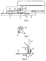
- the holding studs 8 and 9 are secured to the lower side of the horizontal branch 13 of the spreader vane 2 in question, the vertical branch 14 of which on its outward side, i.e. the side facing away from the horizontal branch 13, is provided with a pivot stud 15, the axis of which is substantially parallel to the horizontal branch 13, cf. Figure 5.
- a pressure arm 16 On the pivot stud 15 is pivotably supported a pressure arm 16, shaped and placed in such a manner, that it, together with the carrier disc 1 and the spreader vane 2, forms an over-center mechanism for releasably securing each spreader vane 2 to the carrier disc 1.
- the functioning of the pressure arm 16 can best be explained with reference to Figures 2 and 3.
- the pressure arms 16 is turned from an initial position, in which it is generally perpendicular to the carrier disc 1, through a first angular movement A to the abutment position shown in full lines in Figure 2, in which it abuts against the upper side of the carrier disc 1 with an initial part of a first pressure surface 17.
- the pressure arm 16 is then moved through a second angular movement B, while the radius from the axis of the pivot stud 15 to the first pressure surface 17 increases, until the pressure arm 16 has reached a dead-center position C, in which the radius of the first pressure surface 17 is at a maximum, and where the first pressure surface 17 continues in a second pressure surface 18, the radius of which from this point decreases towards the transition to a third pressure surface 19.
- the movement past the abutment position shown in full lines in Figure 2 can only take place, because the carrier disc 1 and/or the spreader vane 2 can be deflected elastically in the parts being acted upon during this movement. This deflection is, however, not shown in the drawing.
- the pressure arm 16 Since the radius from the axis of the pivot stud 15 to the third pressure surface 19 varies through a minimum - the pressure surface 19 is substantially flat - the pressure arm 16 will, after completing the third angular movement D and taking up the locking position E shown in Figure 3, remain stably in the locking position, in which it is held by the springiness in the spreader vane 2 and/or the carrier disc 1, at the same time as the heads 7 and 8 are held in abutment against the lower side of the carrier disc 1, hence creating a sufficient frictional engagement to prevent the spreader vane 2 from leaving the operating position, in which it has been placed.
- the pressure arm 16 will in the locking position E protrude to such an extent beyond the circumference of the carrier disc 1, that the pressure arm in this position easily may be urged away from the locking position by pushing its freely protruding end upwards.
- a U-shaped pressure shoe 20, the bottom part or connecting part of which constitutes a pressure sole 21, is placed about the part of the pressure arm 16 surrounding the pivot stud 15.
- the pressure shoe 20 is supported on the pivot stud 15 in such a manner, that it can be displaced through a small distance in the longitudinal direction of the long holes, but only to a limited extent in their transverse direction.
- a recess 22 the bottom of which lies in continuation of the pressure surface, and the depth and length of which correspond to the thickness and the length of the pressure sole 21, allows the pressure arm 16 to abut against the carrier disc 1 with the remainder of the surface in question. In this manner, it is avoided that e.g. particles of fertilizer can get jammed between the pressure arm and the carrier disc.
- a further advantage being achieved, so to speak at no extra cost, with the exemplary embodiment shown consists in that the pressure arm 16 in the locking position E shown in Figure 3 acts as a steadying brace for the spreader vane 2 when the latter during the rotation impinges against the material to be spread.
- the mechanism for pulling the stud heads 7 and 8 into abutment with the carrier disc 1 is replaced by a so-called knee-joint or toggle mechanism.
- Such mechanisms are widely known, and a skilled person will be able to adapt them to the present use without other guidance than that provided by the present description.
Landscapes
- Life Sciences & Earth Sciences (AREA)
- Soil Sciences (AREA)
- Environmental Sciences (AREA)
- Catching Or Destruction (AREA)
- Nozzles (AREA)
Claims (6)
- Disque d'épandage rotatif destiné à épandre un matériau capable de s'écouler, du type qui comprend :a) un disque de support plan en forme de plateau (1), etb) au moins une aube d'épandage (2) attachée de façon détachable sur un côté du disque de support (1) au moyen de :c) moyens de fixation détachables (4, 5, 9, 10) comprenantcaractérisé en ce que :c1) dans le disque de support (1) au moins une ouverture (4,5),c2) sur chaque aube d'épandage (2) au moins une barre de maintien (9, 10), dont la tige (11, 12) présente en section transversale une dimension plus petite que sa tête (7, 8), qui est suffisamment petite pour être capable de passer à travers ladite ouverture (4, 5) dans au moins une position par rapport à l'ouverture, etc3) au moins un mécanisme de fixation à actionnement manuel (15-19) adapté à fixer chaque aube d'épandage (2) par rapport au disque de support (1) en tirant ladite tête (7, 8) contre le côté opposé dudit disque (1) de façon à former un engagement de friction qui empêche à chaque aube d'épandage de se déplacer par rapport au disque de support à partir de la position dans laquelle les moyens de fixation ont été actionnés,d) chaque mécanisme de fixation (15-19) comprend un mécanisme à dépassement de point mort adapté à entraíner le mouvement d'un élément de manoeuvre (16) dans une seule et même direction pour les besoins de cette fixation,d1) dans un premier mouvement partiel (A + B) afin de repousser l'aube d'épandage (2) dans une direction en éloignement du disque de support (1) de façon à amener les têtes (7, 8) des barres de maintien (9, 10) en butée contre le côté opposé du disque de support, puis de repousser l'aube d'épandage (2) dans la même direction en éloignement du disque de support (1) avec déflexion élastique de celles des parties du disque de support (1) et/ou de l'aube d'épandage (2) qui sont de ce fait soumises à une charge, ledit premier mouvement partiel (A + B) se terminant à la position de point mort (C), etd2) dans un deuxième mouvement partiel (D) afin de permettre le mouvement desdites parties du disque de support (1) et/ou de l'aube d'épandage (2) qui ont été soumises à une charge pendant ledit deuxième mouvement partiel (A + B), dans la direction opposée au premier mouvement partiel (A + B) mais dans une étendue quelque peu plus courte, de sorte qu'après la fin du deuxième mouvement partiel (D), une partie de ladite déflexion élastique sera conservée, le deuxième mouvement partiel (D) se terminant dans une position de verrouillage (E) dans laquelle l'élément de manoeuvre (16) est tenu par la force élastique qui est exercée par lesdites parties qui sont sous charge,e) les aubes d'épandage (2) et/ou le disque de support (1) ainsi que l'élément de manoeuvre (16) étant conformés et dimensionnés de telle manière que ladite déflexion élastique peut être produite par actionnement manuel de l'élément de manoeuvre, et en ce que la force élastique exercée par lesdites parties sous charge dans ladite position de verrouillage (E) de l'élément de manoeuvre (16) est suffisante pour produire la friction requise entre le disque de support (1) et chaque aube d'épandage (2) pour assurer l'engagement en friction mentionné ci-dessus (dans le point c3), etf) l'élément de manoeuvre (16) a une telle longueur et il est placé d'une telle manière que dans la position de verrouillage (E) il fait saillie vers l'extérieur de la circonférence du disque de support (1).
- Disque d'épandage selon la revendication 1, caractérisé en ce que chaque mécanisme de fixation (15-19) comprend un bras de pression (16) supporté en pivotement autour d'un téton (15) qui s'étend sensiblement parallèlement à la surface du disque de support (1) et fixé à l'aube d'épandage (2), ledit bras de pression comprenant une surface de pression qui s'étend autour du téton (15) et comprenant au moins trois parties (17, 18, 19) placées en séquence, c'est-à-dire une première partie (17) dont la plus grande distance radiale depuis l'axe du téton (15) correspond à la distance entre l'axe du téton et une surface de pression opposée sur le disque support (1), lorsque les têtes (7, 8) des barres de maintien (9, 10) sont légèrement en butée contre le côté opposé du disque de support (1), une deuxième partie (18) dont la distance radiale depuis l'axe du téton (15) est plus grande que la plus grande distance radiale de ladite première partie (17) depuis ledit axe, et une troisième partie (19) dont la distance radiale minimum depuis l'axe du téton (15) est plus grande que la plus grande distance radiale de ladite première partie (17) depuis ledit axe, mais inférieure à la plus grande distance radiale de ladite deuxième partie (18) depuis cet axe.
- Disque d'épandage selon l'une ou l'autre des revendications 1 et 2, du genre sur lequel chaque aube d'épandage (2) a généralement la forme d'une pièce de fer en angle, dont une branche (13) vient buter pendant le fonctionnement contre le disque de support (1), et la deuxième branche (14) vient engager pendant le fonctionnement du matériau capable de s'écouler qui est fourni depuis le dessus, et rejette ce matériau sur les côtés, caractérisé en ce que :a) les barres de maintien (9, 10) ou les ouvertures sont placées sur ou formées dans ladite première branche (13) à une distance depuis ladite deuxième branche (14), etb) chaque élément de fixation (16) est adapté à coopérer avec ladite deuxième branche (14).
- Disque d'épandage selon l'une quelconque des revendications 1 à 3, caractérisé en ce que chaque aube d'épandage (2) est pourvue d'un sabot de pression (20) lequel est ancré sur l'aube d'épandage et comprend une semelle de pression (21), dont l'un des côtés (le côté supérieur à la figure 6) est adapté à coopérer avec la surface de pression (17, 18, 19) du bras de pression (16), et dont le côté opposé est adapté à coopérer avec la surface du disque de support (1).
- Disque d'épandage selon la revendication 4, caractérisé en ce que le sabot de pression (20) est constitué par une pièce de fer plat cintré en forme de U, dans les branches duquel sont ménagés des perçages oblongs (23) qui s'étendent à angle droit pas rapport à la semelle de pression (21), ces perçages étant adaptés à ancrer le sabot de pression sur le téton de pivotement (15), une distance suffisante étant prévue entre la tête du téton de pivotement (15) et la surface de l'aube d'épandage de laquelle fait saillie le téton de pivotement, afin que les branches du U du sabot de pression soient supportées de manière lâche sur chaque côté respectif du bras de pression.
- Disque d'épandage selon la revendication 1, caractérisé en ce que chaque mécanisme de fixation est constitué par un mécanisme à genouillère ou mécanisme à bascule adapté à effectuer un mouvement limité au-delà de la position correspondant à une genouillère "rectiligne".
Applications Claiming Priority (3)
| Application Number | Priority Date | Filing Date | Title |
|---|---|---|---|
| DK1011/92 | 1992-08-12 | ||
| DK101192A DK101192A (da) | 1992-08-12 | 1992-08-12 | Roterende spredeskive med aftagelige vinger til spredning af risledygtigt materiale |
| DK101192 | 1992-08-12 |
Publications (2)
| Publication Number | Publication Date |
|---|---|
| EP0585637A1 EP0585637A1 (fr) | 1994-03-09 |
| EP0585637B1 true EP0585637B1 (fr) | 1999-04-07 |
Family
ID=8099999
Family Applications (1)
| Application Number | Title | Priority Date | Filing Date |
|---|---|---|---|
| EP19930112417 Expired - Lifetime EP0585637B1 (fr) | 1992-08-12 | 1993-08-03 | Disque d'épandage de matériau avec aubes enlevables |
Country Status (3)
| Country | Link |
|---|---|
| EP (1) | EP0585637B1 (fr) |
| DE (1) | DE69324315T2 (fr) |
| DK (2) | DK101192A (fr) |
Families Citing this family (3)
| Publication number | Priority date | Publication date | Assignee | Title |
|---|---|---|---|---|
| EP0635196B1 (fr) * | 1993-07-21 | 1998-01-21 | Rauch Landmaschinenfabrik Gmbh | Epandeur centrifuge |
| US6726131B2 (en) | 2001-12-27 | 2004-04-27 | All-State Industries, Inc. | Rotatable distribution plate for particulate material |
| EP2279654B1 (fr) | 2009-07-28 | 2015-05-20 | CNH Industrial Belgium nv | Ensemble de disque dissipateur convertible pour andainage |
Family Cites Families (4)
| Publication number | Priority date | Publication date | Assignee | Title |
|---|---|---|---|---|
| DE2908949C2 (de) * | 1979-03-07 | 1982-07-15 | Amazonen-Werke H. Dreyer Gmbh & Co Kg, 4507 Hasbergen | Schleuderdüngerstreuer |
| DE3919396A1 (de) * | 1989-06-14 | 1990-12-20 | Amazonen Werke Dreyer H | Zentrifugalduengerstreuer |
| FR2659400B1 (fr) * | 1990-03-08 | 1992-08-14 | Decathlon Production | Dispositif de verrouillage pour la fixation et la solidarisation amovible d'un element supporte sur un support longiforme. |
| DE4100774A1 (de) * | 1990-09-25 | 1992-07-16 | Amazonen Werke Dreyer H | Schnellverschluss fuer die befestigung von wurfschaufeln |
-
1992
- 1992-08-12 DK DK101192A patent/DK101192A/da not_active Application Discontinuation
-
1993
- 1993-08-03 DE DE1993624315 patent/DE69324315T2/de not_active Expired - Fee Related
- 1993-08-03 EP EP19930112417 patent/EP0585637B1/fr not_active Expired - Lifetime
- 1993-08-03 DK DK93112417T patent/DK0585637T3/da active
Also Published As
| Publication number | Publication date |
|---|---|
| DK101192D0 (da) | 1992-08-12 |
| DK101192A (da) | 1994-02-13 |
| DK0585637T3 (da) | 1999-10-18 |
| EP0585637A1 (fr) | 1994-03-09 |
| DE69324315T2 (de) | 1999-11-04 |
| DE69324315D1 (de) | 1999-05-12 |
Similar Documents
| Publication | Publication Date | Title |
|---|---|---|
| US4918820A (en) | Foldable pocket saw | |
| US4134438A (en) | Locking device for threaded fasteners | |
| US5765450A (en) | Bicycle pedal | |
| US5154560A (en) | Self-locking lock nut | |
| JP3053648B2 (ja) | 粘弾性プラスチック部を有する内部人工器官 | |
| CA1306372C (fr) | Mecanisme de verrouillage captif | |
| US5299860A (en) | Snowmobile stud fastener | |
| US5582496A (en) | Top lock jam nut apparatus and method | |
| NL8501175A (nl) | Draagbare balkklem. | |
| JPH05506708A (ja) | ロックねじ付き締付け具 | |
| EP0585637B1 (fr) | Disque d'épandage de matériau avec aubes enlevables | |
| US4758055A (en) | Snowmobile stud | |
| CA2032399C (fr) | Harnais de securite pour monteur/reparateur de lignes | |
| EP0131556B1 (fr) | Rondelle de sûreté se coinçant en deux parties | |
| US5562378A (en) | Lock washer | |
| CA2302613A1 (fr) | Dispositif de serrage a vis automatique | |
| DE3472826D1 (en) | Pipe clip | |
| EP0746696A1 (fr) | Element de fixation a verrouillage | |
| US5988952A (en) | Grooving and threading tool | |
| CA2071713C (fr) | Cle pour fixation de rail | |
| JPS63120081A (ja) | 手持工作機械、殊に研磨盤用の保護フード | |
| US3113758A (en) | Fulcrum attachment for bladed implements | |
| US4392697A (en) | Drawer stop | |
| KR910009201A (ko) | 조절가능한 스포오츠화용 고정기구 및 이것을 구비한 스포오츠화 | |
| CA1165754A (fr) | Guide-foret |
Legal Events
| Date | Code | Title | Description |
|---|---|---|---|
| PUAI | Public reference made under article 153(3) epc to a published international application that has entered the european phase |
Free format text: ORIGINAL CODE: 0009012 |
|
| AK | Designated contracting states |
Kind code of ref document: A1 Designated state(s): DE DK FR GB NL SE |
|
| 17P | Request for examination filed |
Effective date: 19940907 |
|
| 17Q | First examination report despatched |
Effective date: 19951218 |
|
| GRAG | Despatch of communication of intention to grant |
Free format text: ORIGINAL CODE: EPIDOS AGRA |
|
| GRAG | Despatch of communication of intention to grant |
Free format text: ORIGINAL CODE: EPIDOS AGRA |
|
| GRAH | Despatch of communication of intention to grant a patent |
Free format text: ORIGINAL CODE: EPIDOS IGRA |
|
| GRAH | Despatch of communication of intention to grant a patent |
Free format text: ORIGINAL CODE: EPIDOS IGRA |
|
| GRAA | (expected) grant |
Free format text: ORIGINAL CODE: 0009210 |
|
| AK | Designated contracting states |
Kind code of ref document: B1 Designated state(s): DE DK FR GB NL SE |
|
| PG25 | Lapsed in a contracting state [announced via postgrant information from national office to epo] |
Ref country code: SE Free format text: THE PATENT HAS BEEN ANNULLED BY A DECISION OF A NATIONAL AUTHORITY Effective date: 19990407 |
|
| REF | Corresponds to: |
Ref document number: 69324315 Country of ref document: DE Date of ref document: 19990512 |
|
| ET | Fr: translation filed | ||
| PG25 | Lapsed in a contracting state [announced via postgrant information from national office to epo] |
Ref country code: GB Free format text: LAPSE BECAUSE OF NON-PAYMENT OF DUE FEES Effective date: 19990803 |
|
| REG | Reference to a national code |
Ref country code: DK Ref legal event code: T3 |
|
| PLBE | No opposition filed within time limit |
Free format text: ORIGINAL CODE: 0009261 |
|
| GBPC | Gb: european patent ceased through non-payment of renewal fee |
Effective date: 19990803 |
|
| 26N | No opposition filed | ||
| PGFP | Annual fee paid to national office [announced via postgrant information from national office to epo] |
Ref country code: DK Payment date: 20020830 Year of fee payment: 10 |
|
| PG25 | Lapsed in a contracting state [announced via postgrant information from national office to epo] |
Ref country code: DK Free format text: LAPSE BECAUSE OF NON-PAYMENT OF DUE FEES Effective date: 20030901 |
|
| REG | Reference to a national code |
Ref country code: DK Ref legal event code: EBP |
|
| PGFP | Annual fee paid to national office [announced via postgrant information from national office to epo] |
Ref country code: FR Payment date: 20060724 Year of fee payment: 14 |
|
| PGFP | Annual fee paid to national office [announced via postgrant information from national office to epo] |
Ref country code: NL Payment date: 20060726 Year of fee payment: 14 |
|
| PGFP | Annual fee paid to national office [announced via postgrant information from national office to epo] |
Ref country code: DE Payment date: 20060831 Year of fee payment: 14 |
|
| PG25 | Lapsed in a contracting state [announced via postgrant information from national office to epo] |
Ref country code: NL Free format text: LAPSE BECAUSE OF NON-PAYMENT OF DUE FEES Effective date: 20080301 |
|
| NLV4 | Nl: lapsed or anulled due to non-payment of the annual fee |
Effective date: 20080301 |
|
| REG | Reference to a national code |
Ref country code: FR Ref legal event code: ST Effective date: 20080430 |
|
| PG25 | Lapsed in a contracting state [announced via postgrant information from national office to epo] |
Ref country code: DE Free format text: LAPSE BECAUSE OF NON-PAYMENT OF DUE FEES Effective date: 20080301 |
|
| PG25 | Lapsed in a contracting state [announced via postgrant information from national office to epo] |
Ref country code: FR Free format text: LAPSE BECAUSE OF NON-PAYMENT OF DUE FEES Effective date: 20070831 |