EP0585663B1 - Elément de revêtement pour sols, plafonds et murs - Google Patents
Elément de revêtement pour sols, plafonds et murs Download PDFInfo
- Publication number
- EP0585663B1 EP0585663B1 EP93112766A EP93112766A EP0585663B1 EP 0585663 B1 EP0585663 B1 EP 0585663B1 EP 93112766 A EP93112766 A EP 93112766A EP 93112766 A EP93112766 A EP 93112766A EP 0585663 B1 EP0585663 B1 EP 0585663B1
- Authority
- EP
- European Patent Office
- Prior art keywords
- plate
- support
- cover plate
- edges
- cladding
- Prior art date
- Legal status (The legal status is an assumption and is not a legal conclusion. Google has not performed a legal analysis and makes no representation as to the accuracy of the status listed.)
- Expired - Lifetime
Links
Images


Classifications
-
- E—FIXED CONSTRUCTIONS
- E04—BUILDING
- E04F—FINISHING WORK ON BUILDINGS, e.g. STAIRS, FLOORS
- E04F13/00—Coverings or linings, e.g. for walls or ceilings
- E04F13/07—Coverings or linings, e.g. for walls or ceilings composed of covering or lining elements; Sub-structures therefor; Fastening means therefor
- E04F13/08—Coverings or linings, e.g. for walls or ceilings composed of covering or lining elements; Sub-structures therefor; Fastening means therefor composed of a plurality of similar covering or lining elements
- E04F13/14—Coverings or linings, e.g. for walls or ceilings composed of covering or lining elements; Sub-structures therefor; Fastening means therefor composed of a plurality of similar covering or lining elements stone or stone-like materials, e.g. ceramics concrete; of glass or with an outer layer of stone or stone-like materials or glass
- E04F13/144—Coverings or linings, e.g. for walls or ceilings composed of covering or lining elements; Sub-structures therefor; Fastening means therefor composed of a plurality of similar covering or lining elements stone or stone-like materials, e.g. ceramics concrete; of glass or with an outer layer of stone or stone-like materials or glass with an outer layer of marble or other natural stone
-
- E—FIXED CONSTRUCTIONS
- E04—BUILDING
- E04C—STRUCTURAL ELEMENTS; BUILDING MATERIALS
- E04C2/00—Building elements of relatively thin form for the construction of parts of buildings, e.g. sheet materials, slabs, or panels
- E04C2/30—Building elements of relatively thin form for the construction of parts of buildings, e.g. sheet materials, slabs, or panels characterised by the shape or structure
- E04C2/34—Building elements of relatively thin form for the construction of parts of buildings, e.g. sheet materials, slabs, or panels characterised by the shape or structure composed of two or more spaced sheet-like parts
- E04C2/36—Building elements of relatively thin form for the construction of parts of buildings, e.g. sheet materials, slabs, or panels characterised by the shape or structure composed of two or more spaced sheet-like parts spaced apart by transversely-placed strip material, e.g. honeycomb panels
- E04C2/365—Building elements of relatively thin form for the construction of parts of buildings, e.g. sheet materials, slabs, or panels characterised by the shape or structure composed of two or more spaced sheet-like parts spaced apart by transversely-placed strip material, e.g. honeycomb panels by honeycomb structures
-
- E—FIXED CONSTRUCTIONS
- E04—BUILDING
- E04F—FINISHING WORK ON BUILDINGS, e.g. STAIRS, FLOORS
- E04F15/00—Flooring
- E04F15/02—Flooring or floor layers composed of a number of similar elements
-
- Y—GENERAL TAGGING OF NEW TECHNOLOGICAL DEVELOPMENTS; GENERAL TAGGING OF CROSS-SECTIONAL TECHNOLOGIES SPANNING OVER SEVERAL SECTIONS OF THE IPC; TECHNICAL SUBJECTS COVERED BY FORMER USPC CROSS-REFERENCE ART COLLECTIONS [XRACs] AND DIGESTS
- Y10—TECHNICAL SUBJECTS COVERED BY FORMER USPC
- Y10T—TECHNICAL SUBJECTS COVERED BY FORMER US CLASSIFICATION
- Y10T428/00—Stock material or miscellaneous articles
- Y10T428/24—Structurally defined web or sheet [e.g., overall dimension, etc.]
- Y10T428/24149—Honeycomb-like
- Y10T428/24165—Hexagonally shaped cavities
Definitions
- the invention relates to wall and ceiling cladding elements held on mounting rails with the features of the preamble of claim 1.
- FR-A-1279466 shows a cladding element, which is used for sound and heat protection, in principle of similar construction, but in which a natural stone slab on the visible surface and anchoring elements on the back are missing.
- the honeycomb-shaped carrier plate consists of cardboard.
- the honeycombs of the carrier panel protrude from the cover panels at two corners lying above them and insert pockets remain at the other two edges, the cladding panels can only be assembled by moving within the plate level possible.
- the known cladding panels can only be attached to building walls or ceilings using adhesive.
- the object of the invention is to provide a mechanical fastening system using support rails for the cladding elements, which allows a forced insertion of the cladding element into the panel assembly in such a way that a simultaneous nesting of the cladding element to be used is made possible at two corners with the panel assembly.
- Support rails with oblique slots for hanging facade panels provided with sheet metal hooks are known per se, however, the oblique slots are oriented differently, because the facade panel is moved towards the wall during hanging, while according to the invention the oblique slots are designed such that the cladding element in the Level of the composite panel is brought into position.
- the honeycombs e.g. from regular hexagons, only one single direction of movement of the cladding elements is possible in order to nest them on two edges lying above the existing composite panel. This angle is then exactly 30 °. Accordingly, the guide slots in the mounting rails according to the invention form such an angle with the longitudinal direction of the rails.
- the system according to the invention of mounting rails and cladding elements is very easy to assemble, since the mounting rails can be mounted both vertically and horizontally on a building wall and the guide slots in the mounting rails ensure that the cladding elements are quickly fitted, since these are automatically guided into the fitting position.
- the guide slots run down to the longitudinal center of the mounting rails, so that the weight of the cladding elements secures them in their fitting position. Thanks to the all-round nesting of each cladding element in the composite, the façade is absolutely flush with the surface and extremely stable.
- a cladding element 10 has a honeycomb-shaped carrier plate 12 made of plastic and two cover plates 14, 16 placed on opposite end faces, between which the carrier plate 12 is sandwiched.
- the two cover plates 14, 16 are braced with the support plate 12 by means of tension anchors 18.
- On the top Plate 14 has an adhesive layer 20 applied, by means of which a natural stone plate 22 is glued to the plate 14 made of metal.
- the carrier plate 12 has a number of cavities 13 which are closed circumferentially by strong partition walls 15.
- the cavities 13 form cylindrical tubes with a constant cross section.
- a regular hexagonal cross section is shown in the exemplary embodiments.
- the carrier plate 12 has an opening 17 and a corresponding floor 19 which is integrally connected to the partition walls 15 and has a corresponding floor 19.
- the two cover plates 14, 16 can additionally be glued to these two.
- the cavities 13 are filled with an insulating material 24 in order to increase the thermal and impact sound insulation properties.
- the cladding elements are prefabricated as standard and can then be easily installed by pushing them together at the construction site, the carrier plates each interlocking with two adjacent cladding elements 10, so that a stable bond is created.
- the metal plates 14, 16 protrude at two edges lying above the stone plate 22 and are set back at the other two edges, so that the butt joint between two stone plates 22 is closed on the bottom side by the protruding metal plate 14 of the one cladding element 10.
- the joint has the reference number 26.
- the cover plates 14, 16 can be seen with solid lines, between which the joints 29 are formed.
- the edges of the stone slabs 22 are shown in dash-dot lines and the walls 15 of the support slab 12, which here consists of a section of an extrusion profile, can be seen in broken lines.
- the cover plates 14, 16 and the stone plates 22 have at least approximately the same rectangular format and the support plate 12 is affected by an imaginary rectangular box on the outside, which is larger in length and width than the format of the cover plates.
- the carrier plate 12 protrudes from the edges of the metal plates 14, 16 at two corners, one with trapezoidal protrusions 21 and the other with triangular protrusions 23.
- Correspondingly configured recesses 25, 27 are provided on the other two edges, for the positive engagement of one attached lining element 10 serve.
- four tension anchors 18 are sufficient to brace the cover plates 14, 16 with the carrier plate 12.
- the stone slab 22 is offset diagonally to the cover slabs, so that the butt joints 26 are offset between the stone slabs 22 and the cover slab joints 29.
- the cladding element is assembled in the composite by a sliding movement in the panel plane in only one very specific direction, which is shown in FIG. 4 is indicated by the arrow 31.
- This direction runs parallel to a hexagon side of a honeycomb which adjoins one of the parallel sides of the hexagon.
- This insertion direction forms an angle of 60 ° with the longitudinal edges of the cover plates 14, 16 which are protruded by the trapezoidal projections 21 or recesses 25 and an angle of 30 ° with the transverse edges of the cover plates, to which the triangular projections 23 and recesses 27 are assigned.
- the cladding element 10 is nested in a form-fitting manner at two edges lying at the same time with the panel assembly.
- the in FIG. 4 corner honeycomb shown at the top left summarizes a projection 21 and a projection 23 and is overlapped in the composite of three adjacent cover plates 14, 16.
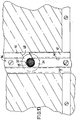
- the anchors 18 ' protrude above the lower cover plate 16 and have a screwed-on anchoring element 28.
- the anchor 18 ' consists of a screw, the head of which is essentially flush with the top of the cover plate 14 and at most protrudes into the adhesive layer 20.
- the anchoring element 28 has a hexagon collar 30 for bracing.
- a shaft 32 adjoins the collar 30 and connects the collar 30 to a circular flange 34.
- the anchoring element 28 has a continuous internal thread.
- Collar 30, shaft 32 and support flange 34 form the one-piece anchoring element 28.
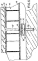
- the support flange 34 fits into a C-shaped support rail 36 which is screwed onto a building wall in a known manner by means of screws 38 and dowels (not shown).
- the support rail 36 is shown in FIG. 9 shown in detail. It has a longitudinal slot 40 between the two top walls 42 and the width of this longitudinal slot 40 is dimensioned such that the shaft 32 of the anchoring element 28 has space therein.
- the distance of the collar 30 from the support flange 34, which corresponds to the shaft length, is slightly larger than the thickness of the top walls 42, so that there is space between the collar 30 and the support flange 34.
- the diameter of the support flange 34 is approximately equal to the inside width of the mounting rail 36.
- the mounting rail 36 has in a side wall 44 a number of spaced-apart rectangular insertion openings 46 through which the mounting flanges 34 of the anchors 18 'fit.
- Each of the insertion openings 46 is adjoined in the adjacent top wall 42 by a guide slot 48 which opens into the longitudinal slot 40.
- the guide slot 48 forms an angle of at least approximately 30 ° with the transverse direction of the mounting rail 36, and when the mounting rail 36 is mounted vertically, the guide slot 48 extends obliquely downward from the rail side wall to the longitudinal slot 40.
- the width of the guide slot 48 is smaller than that of the insertion opening 46 and approximately equal to the diameter of the shaft 32.
- the trim elements 10 are suspended from the side in the mounting rails 36, as shown in FIG. 8 illustrates this.
- the four support flanges 34 of the anchoring elements 28 are inserted into the lateral insertion openings 46, after which the shafts 32 enter the guide slots 48.
- the lining element 10 slides both to the left and downwards until the shaft 32 abuts the edge of the left-hand top wall 42 (FIG. 8).
- the shaft 32 is then supported approximately diametrically opposite at the corner between the lower edge of the guide slot 48 and the edge of the right-hand top wall 42 (FIG. 10).
- the two differently contoured edges of the carrier plate 12 reach the complementary edge configurations of the two adjacent carrier plates of the previously suspended cladding elements.
- the positive connection at both edges of the cladding elements lying at right angles to one another thus takes place simultaneously.
- FIG. 7 illustrates a slight modification of a cladding element 10 in that the cover-side separate plate 14 is provided with four recessed embossments 50. These embossments 50 are designed such that they fit into the contour of a cavity 13 of the carrier plate 12 in a form-fitting manner. The depressions 50 stiffen the plate 14 once and serve to receive a broad head 52 of the armature 18 or 18 '.
- a rail with a box-shaped hollow profile i.e. with a continuous top wall, can also be used.
- the guide slots then extend beyond the middle of the rail by half the anchor shaft diameter.
- the carrier plate 12 can also have circular honeycombs, for example.
- the projections then have a circular segment contour on both corners of the carrier plate lying at the corners.
- the mutual interlocking results only in line contact instead of the surface contacts in the case of hexagonal honeycombs.
- the parallel sides of the hexagon that is to say the sides parallel to the edges of the sides of the cover plate, can also be longer or shorter than the other sides . This also changes the insertion angle. These parallel sides can also shrink to the value 0, so that the hexagon becomes a parallelogram or a rhombus.
- Such quadrangular oblique honeycomb cross sections are also expressly within the scope of the invention.
- the projections can then be triangular on both corner plate edges and their apex angle is 90 ° in the case of a square.
- the insertion angle of the cladding element in the composite is then 45 °.
- the two cover plates 14, 16 can be attached to the carrier plate instead of or in addition to the mechanical anchors 18 by gluing.
Landscapes
- Engineering & Computer Science (AREA)
- Architecture (AREA)
- Civil Engineering (AREA)
- Structural Engineering (AREA)
- Chemical & Material Sciences (AREA)
- Ceramic Engineering (AREA)
- Finishing Walls (AREA)
- Floor Finish (AREA)
- Panels For Use In Building Construction (AREA)
Claims (3)
- Eléments de revêtement pour murs et plafonds, supportés sur des rails porteurs (36), qui présentent, chacun, une plaque-support (12) en nids d'abeilles disposée en sandwich entre une plaque de recouvrement rectangulaire supérieure (14) et une plaque de recouvrement inférieure (16) ou des éléments de plaque de revêtement inférieurs individuels et assemblée avec ceux-ci, par exemple, par des ancres mécaniques (18), et une dalle (22), fixée sur la plaque de recouvrement supérieure (14), présentant au moins environ le même format que cette dernière, les nids d'abeilles de la plaque-support (12) faisant partiellement saillie, sur deux bords diagonalement opposés d'au moins l'une des plaques de recouvrement (14; 16), par rapport à cette dernière et formant, le long des deux autres bords, des poches en retrait par rapport à la plaque de recouvrement (14), de sorte que, lorsque les plaques sont assemblées, la plaque-support (12) d'un élément de revêtement (10) vient, sur les quatre bords, en prise en liaison de forme, en forme de denture, avec les plaques-supports (12) d'éléments de revêtement adjacents (10) et que les plaques de recouvrement supérieures (14) de toutes les plaques de revêtement (10) viennent, par leurs bords, au moins environ en butée l'une contre l'autre, et de la plaque de recouvrement inférieure (16) ressortant des éléments d'ancrage (28) qui peuvent s'engager dans des évidements (40, 48) des rails porteurs (36), caractérisés en ce que chaque rail porteur (36) consiste en un profilé creux de section sensiblement rectangulaire et présente une paroi inférieure, deux parois latérales et une paroi supérieure (42) éventuellement interrompue par une fente longitudinale (40), et que dans l'une des parois latérales (44) sont prévues un nombre d'ouvertures (46), pour l'insertion, dans chacune, d'une bride de support (34) à l'extrémité de chaque élément d'ancrage (28) de l'élément de revêtement (10), qui sont suivies, chacune, d'une fente de guidage (48), prévue dans la demi-paroi supérieure (42) adjacente du rail porteur (36), dont la largeur est inférieure à celle de l'ouverture d'insertion (46) et qui est destinée au passage d'une tige (32) de l'élément d'ancrage (28), et que les fentes de guidage (48) forment, chacune, avec l'extension longitudinale du rail porteur (36), un angle aigu de l'ordre de 25° à 65°.
- Eléments de revêtement supportés sur des rails porteurs suivant la revendication 1, caractérisés en ce que l'angle que forment les fentes de guidage (48) de chaque rail porteur (36) avec le sens longitudinal ou transversal de celui-ci est d'au moins environ 30°.
- Eléments de revêtement supportés sur des rails porteurs suivant la revendication 1 ou 2, caractérisés en ce que les fentes de guidage (48) de chaque rail porteur (36) se présentent sous forme de fentes de liaison aboutissant dans la fente longitudinale (40).
Applications Claiming Priority (2)
| Application Number | Priority Date | Filing Date | Title |
|---|---|---|---|
| DE4226742 | 1992-08-13 | ||
| DE4226742A DE4226742A1 (de) | 1992-08-13 | 1992-08-13 | Verkleidungselement für Böden, Decken, Wände und Fassaden |
Publications (2)
| Publication Number | Publication Date |
|---|---|
| EP0585663A1 EP0585663A1 (fr) | 1994-03-09 |
| EP0585663B1 true EP0585663B1 (fr) | 1996-01-03 |
Family
ID=6465429
Family Applications (1)
| Application Number | Title | Priority Date | Filing Date |
|---|---|---|---|
| EP93112766A Expired - Lifetime EP0585663B1 (fr) | 1992-08-13 | 1993-08-10 | Elément de revêtement pour sols, plafonds et murs |
Country Status (4)
| Country | Link |
|---|---|
| US (1) | US5390468A (fr) |
| EP (1) | EP0585663B1 (fr) |
| AT (1) | ATE132560T1 (fr) |
| DE (2) | DE4226742A1 (fr) |
Cited By (1)
| Publication number | Priority date | Publication date | Assignee | Title |
|---|---|---|---|---|
| CN103866948A (zh) * | 2014-03-26 | 2014-06-18 | 山东富达装饰工程有限公司 | 石材面层蜂窝地板 |
Families Citing this family (34)
| Publication number | Priority date | Publication date | Assignee | Title |
|---|---|---|---|---|
| JP2870625B2 (ja) * | 1993-03-11 | 1999-03-17 | 株式会社日建設計 | ハニカムカーテンウォールおよび該ハニカムカーテンウォールに用いるハニカムパネル |
| DE9416191U1 (de) * | 1994-10-07 | 1994-12-01 | Dorenwendt, Wolfgang, 37359 Wachstedt | Balkonfußboden |
| US5992112A (en) * | 1996-08-27 | 1999-11-30 | Josey Industrial Technologies, Inc. | Modular building floor structure |
| DE59706558D1 (de) * | 1997-07-28 | 2002-04-11 | Alstom | Keramische Auskleidung |
| US5899037A (en) * | 1997-07-29 | 1999-05-04 | Josey; Gary L. | Composite wall structure |
| DE19960508B4 (de) * | 1999-12-15 | 2004-08-05 | Schwörer Haus GmbH & Co. | Trockenestrichelement |
| US6588171B2 (en) | 2000-11-29 | 2003-07-08 | Scienda, Llc | Cellular-core structural panel, and building structure incorporating same |
| EP1288590B1 (fr) * | 2001-09-03 | 2007-05-02 | Peter Oesch | Appareil de fabrication de panneaux d'isolation transparents et méthode de fabrication desdits panneaux |
| US20030066259A1 (en) * | 2001-09-10 | 2003-04-10 | Sudweeks Dan L. | Fastener system and method for attaching manufactured brick or stone to a surface |
| US20040144052A1 (en) * | 2003-01-17 | 2004-07-29 | Long Douglas A. | Suspended ceiling system |
| ITMO20030103A1 (it) * | 2003-04-11 | 2004-10-12 | System Spa | Elemento ceramico per pavimenti e/o rivestimenti. |
| KR100513152B1 (ko) * | 2005-05-12 | 2005-09-08 | 경일산업 주식회사 | 건축판재 레일식 고정구 및 그를 이용한 건축판재 부착방법 |
| CA2619575A1 (fr) * | 2005-08-17 | 2007-02-22 | Kingspan Research And Developments Limited | Systeme de revetement de plancher d'elements plancher de type sandwich dotes d'un noyau en materiau isolant |
| TWM290175U (en) * | 2005-09-20 | 2006-05-01 | Chian-Hung Ju | Structure of the light building materials with sound absorption and insulation function |
| CN101336774B (zh) * | 2006-07-13 | 2010-07-21 | 黄桂芳 | 超薄石材蜂窝板的家具、厨卫台面制造方法 |
| CN100500053C (zh) * | 2006-07-13 | 2009-06-17 | 黄桂芳 | 超薄石材蜂窝板的家具、厨卫台面制造方法 |
| ITMI20061916A1 (it) * | 2006-10-05 | 2008-04-06 | Natural Stone Tech S R L | Pannello sandwich di rivestimento e metodo per la sua fabbricazione |
| WO2009095936A1 (fr) * | 2008-01-28 | 2009-08-06 | Calvasina S.P.A. | Panneau de revêtement composite |
| US8806838B2 (en) * | 2012-08-17 | 2014-08-19 | Daebo Housing Co., Ltd | Lightweight stone insulating panel and construction method for insulating building exterior using the same |
| US9068347B2 (en) | 2012-12-07 | 2015-06-30 | Illinois Tool Works Inc. | Curtain wall panel bracket leveling system |
| US8955285B2 (en) | 2012-12-07 | 2015-02-17 | Illinois Tool Works Inc. | Embedment attachment system |
| US9663961B2 (en) | 2012-12-07 | 2017-05-30 | Illinois Tool Works Inc. | Curtain wall panel installation system |
| US12595658B2 (en) | 2013-10-25 | 2026-04-07 | Mbrico, Llc | Tile and support structure for vertical mounting tiles |
| US11199007B2 (en) * | 2013-10-25 | 2021-12-14 | Mbrico, Llc | Tile and support structure |
| US10041254B2 (en) | 2013-10-25 | 2018-08-07 | Mbrico, Llc | Tile and support structure |
| US9151063B2 (en) | 2013-10-25 | 2015-10-06 | Mbrico, Llc | Tile and support structure |
| US11371245B2 (en) | 2013-10-25 | 2022-06-28 | Mbrico, Llc | Tile and support structure |
| US10988931B1 (en) | 2013-10-25 | 2021-04-27 | Mbrico, Llc | Tile and support structure |
| CN105346150A (zh) * | 2015-12-10 | 2016-02-24 | 黄立群 | 一种具有二次成型结构的空心板及其制作工艺 |
| US11982087B2 (en) | 2019-05-17 | 2024-05-14 | Mbrico, Llc | Tile and support structure |
| CN112177237A (zh) * | 2020-11-12 | 2021-01-05 | 新化县东泰特种耐火材料有限公司 | 一种带饰面稳定层的节能板材 |
| NL2027014B1 (en) * | 2020-11-30 | 2022-07-04 | Holland Composites Bv | Renewable lightweight composite assembly |
| GB2700096A (en) * | 2023-12-15 | 2025-09-24 | Autex Industries Ltd | Fixing of pet panels to allow for recycling |
| US20250303662A1 (en) * | 2024-03-28 | 2025-10-02 | General Electric Company | Composite panels having an integrated attachment feature and methods for making the same |
Family Cites Families (28)
| Publication number | Priority date | Publication date | Assignee | Title |
|---|---|---|---|---|
| NL45242C (fr) * | 1935-02-28 | |||
| BE464442A (fr) * | 1941-10-27 | |||
| US2793718A (en) * | 1950-01-25 | 1957-05-28 | Glenn L Martin Co | Honeycomb panel and method of making same |
| DE1823819U (de) * | 1958-12-06 | 1960-12-22 | Hinrich Reimers G M B H | Raumverkleidungsplatte. |
| US3078002A (en) * | 1959-05-21 | 1963-02-19 | North American Aviation Inc | Fastener |
| FR1279466A (fr) * | 1960-11-10 | 1961-12-22 | éléments alvéolaires pour panneaux de construction ou d'emballage | |
| US3579942A (en) * | 1969-12-05 | 1971-05-25 | Thomas & Betts Corp | Fastener anchored in honeycomb panel |
| US3723233A (en) * | 1971-07-15 | 1973-03-27 | P Bourke | Marble faced wall panels and method of making same |
| FR2189604B1 (fr) * | 1972-06-20 | 1974-10-25 | Berthelier Louis | |
| IE39063B1 (en) * | 1972-09-04 | 1978-08-02 | Patric Terence Bourke | Stone faced surface element and method and apparatus for the manufacture thereof |
| DE2251268A1 (de) * | 1972-10-19 | 1974-05-02 | Wilhelm Berger | Verbundplatte |
| FR2205078A5 (fr) * | 1972-10-31 | 1974-05-24 | Francon Francis | |
| DE2336700A1 (de) * | 1973-07-19 | 1975-02-06 | Ferma | Fertigbauelement |
| GB2047375B (en) * | 1979-04-12 | 1983-01-06 | Campbell P | Fixing device for securing cladding panels to walls |
| DE7913876U1 (de) * | 1979-05-14 | 1979-08-16 | Becher, Karl | Ankerelement zum miteinanderverbinden der aussenschalen eines mehrschichtigen betonbauelements |
| DE7929402U1 (de) * | 1979-10-17 | 1980-03-13 | Frimeda Metall- Und Drahtwarenfabrik, Siegfried Fricker, 7135 Wiernsheim | Befestigungsvorrichtung, insbesondere fuer die verbindung von zwei bauteilen von bauwerken |
| DE3128246A1 (de) * | 1981-07-17 | 1983-02-24 | Klaus 7928 Giengen Wöbke | Verblendmauerwerk-elemente montagesystem |
| GB2143000B (en) * | 1983-07-06 | 1986-12-10 | Mallinson Denny | Modular panel assembly for vehicle bodies |
| DE3337875A1 (de) * | 1983-10-18 | 1985-04-25 | Keramikindustrieanlagen W.Strohmenger GmbH & Co KG, 8524 Neunkirchen | Keramische tragplatte |
| US4925721A (en) * | 1984-08-27 | 1990-05-15 | Lockheed Corporation | Honeycomb sandwich structure having dissimilar metal face sheets |
| US4601147A (en) * | 1985-08-16 | 1986-07-22 | Neil Migliore | Assembly system for installing marble panels |
| US4822661A (en) * | 1987-07-20 | 1989-04-18 | Battaglia Gino C | Lightweight stone furniture |
| CH674540A5 (fr) * | 1987-08-07 | 1990-06-15 | Roman Breitenmoser | |
| DE3727157A1 (de) * | 1987-08-14 | 1989-02-23 | Ottmar Muehlberger | Naturstein-verkleidungslement und verfahren zu seiner herstellung |
| DE3921921A1 (de) * | 1989-07-04 | 1991-01-17 | Schmidlin Hans | Verkleidungstafel |
| DE3937087A1 (de) * | 1989-11-07 | 1991-05-08 | Clouth Gummiwerke Ag | Mit einer panzerplatte versehenes bauteil |
| DE9006046U1 (de) * | 1990-05-29 | 1990-08-09 | Zierer, Rudolf, 4432 Gronau | Fliesenplatte |
| DE9202055U1 (de) * | 1991-09-06 | 1992-04-16 | AP Steinpaneel GmbH, 5440 Mayen | Fassadenplatte |
-
1992
- 1992-08-13 DE DE4226742A patent/DE4226742A1/de not_active Withdrawn
-
1993
- 1993-08-10 AT AT93112766T patent/ATE132560T1/de not_active IP Right Cessation
- 1993-08-10 EP EP93112766A patent/EP0585663B1/fr not_active Expired - Lifetime
- 1993-08-10 DE DE59301312T patent/DE59301312D1/de not_active Expired - Fee Related
- 1993-08-12 US US08/105,595 patent/US5390468A/en not_active Expired - Fee Related
Cited By (1)
| Publication number | Priority date | Publication date | Assignee | Title |
|---|---|---|---|---|
| CN103866948A (zh) * | 2014-03-26 | 2014-06-18 | 山东富达装饰工程有限公司 | 石材面层蜂窝地板 |
Also Published As
| Publication number | Publication date |
|---|---|
| ATE132560T1 (de) | 1996-01-15 |
| US5390468A (en) | 1995-02-21 |
| DE4226742A1 (de) | 1994-02-17 |
| DE59301312D1 (de) | 1996-02-15 |
| EP0585663A1 (fr) | 1994-03-09 |
Similar Documents
| Publication | Publication Date | Title |
|---|---|---|
| EP0585663B1 (fr) | Elément de revêtement pour sols, plafonds et murs | |
| DE1929175A1 (de) | Wand,insbesondere Trennwandsystem | |
| DE602005004148T2 (de) | Abziehbalken | |
| EP0560013B1 (fr) | Panneau en bois | |
| DE2355314A1 (de) | Verkleidungsaufbau zum anbringen von tafeln | |
| WO1997039204A1 (fr) | Module de construction et systeme de modules de construction pour la realisation de constructions plates, en particulier de murs | |
| DE60314459T2 (de) | Bauelement für die mantelbetonbauweise | |
| DE2226889A1 (de) | Bausystem, insbesondere zur Ernch tung von Gebäuden, Container und Fahr zeugaufbauten | |
| DE3408390A1 (de) | Raumzelle | |
| DD237529A5 (de) | Plattenfoermiges bauelement und baukonstruktion mit derartigen bauelementen | |
| DE4036735C2 (de) | Deckenelement für eine Brandschutz-Zwischendecke | |
| EP0364768B1 (fr) | Elément de cloison de séparation | |
| DE9302447U1 (de) | Holzbautafel | |
| DE9207654U1 (de) | Holzbautafel | |
| EP0111857B1 (fr) | Méthode de construction pour revêtement et subdivision d'un espace | |
| DE3214502C2 (fr) | ||
| DE2556589A1 (de) | Vorgefertigte, isolierende bauplatte und verfahren zu ihrer herstellung | |
| EP1918469B1 (fr) | Système de raccordement d'isolation thermique | |
| EP0898026A2 (fr) | Maison préfabriquée | |
| EP1437450A1 (fr) | Elément de construction de paroi | |
| DE1931427C3 (de) | Wandkonstruktion für Bauwerke | |
| EP0950604A2 (fr) | Elément de construction pour la réalisation de murs et/ou de plafonds, en particulier sur des bateaux | |
| DE1609741A1 (de) | Wandplattensystem | |
| DE9214484U1 (de) | Vorrichtung zum abgewinkelten Verbinden vorzugsweise flächiger Teile | |
| EP1203184B1 (fr) | Enveloppe isolante pour filtre electrique |
Legal Events
| Date | Code | Title | Description |
|---|---|---|---|
| PUAI | Public reference made under article 153(3) epc to a published international application that has entered the european phase |
Free format text: ORIGINAL CODE: 0009012 |
|
| AK | Designated contracting states |
Kind code of ref document: A1 Designated state(s): AT BE CH DE ES FR GB GR IT LI NL PT SE |
|
| 17P | Request for examination filed |
Effective date: 19940322 |
|
| 17Q | First examination report despatched |
Effective date: 19950404 |
|
| GRAA | (expected) grant |
Free format text: ORIGINAL CODE: 0009210 |
|
| AK | Designated contracting states |
Kind code of ref document: B1 Designated state(s): AT BE CH DE ES FR GB GR IT LI NL PT SE |
|
| PG25 | Lapsed in a contracting state [announced via postgrant information from national office to epo] |
Ref country code: NL Free format text: LAPSE BECAUSE OF FAILURE TO SUBMIT A TRANSLATION OF THE DESCRIPTION OR TO PAY THE FEE WITHIN THE PRESCRIBED TIME-LIMIT Effective date: 19960103 Ref country code: GR Free format text: LAPSE BECAUSE OF FAILURE TO SUBMIT A TRANSLATION OF THE DESCRIPTION OR TO PAY THE FEE WITHIN THE PRESCRIBED TIME-LIMIT Effective date: 19960103 Ref country code: ES Free format text: THE PATENT HAS BEEN ANNULLED BY A DECISION OF A NATIONAL AUTHORITY Effective date: 19960103 Ref country code: BE Effective date: 19960103 |
|
| REF | Corresponds to: |
Ref document number: 132560 Country of ref document: AT Date of ref document: 19960115 Kind code of ref document: T |
|
| REF | Corresponds to: |
Ref document number: 59301312 Country of ref document: DE Date of ref document: 19960215 |
|
| GBT | Gb: translation of ep patent filed (gb section 77(6)(a)/1977) |
Effective date: 19960125 |
|
| REG | Reference to a national code |
Ref country code: CH Ref legal event code: NV Representative=s name: E. BLUM & CO. PATENTANWAELTE |
|
| ITF | It: translation for a ep patent filed | ||
| ET | Fr: translation filed | ||
| PG25 | Lapsed in a contracting state [announced via postgrant information from national office to epo] |
Ref country code: SE Effective date: 19960403 Ref country code: PT Effective date: 19960403 |
|
| NLV1 | Nl: lapsed or annulled due to failure to fulfill the requirements of art. 29p and 29m of the patents act | ||
| PGFP | Annual fee paid to national office [announced via postgrant information from national office to epo] |
Ref country code: FR Payment date: 19960730 Year of fee payment: 4 |
|
| PGFP | Annual fee paid to national office [announced via postgrant information from national office to epo] |
Ref country code: CH Payment date: 19960731 Year of fee payment: 4 |
|
| PGFP | Annual fee paid to national office [announced via postgrant information from national office to epo] |
Ref country code: AT Payment date: 19960813 Year of fee payment: 4 |
|
| PGFP | Annual fee paid to national office [announced via postgrant information from national office to epo] |
Ref country code: DE Payment date: 19961018 Year of fee payment: 4 |
|
| PLBE | No opposition filed within time limit |
Free format text: ORIGINAL CODE: 0009261 |
|
| 26N | No opposition filed | ||
| PG25 | Lapsed in a contracting state [announced via postgrant information from national office to epo] |
Ref country code: GB Free format text: LAPSE BECAUSE OF NON-PAYMENT OF DUE FEES Effective date: 19970810 Ref country code: AT Free format text: LAPSE BECAUSE OF NON-PAYMENT OF DUE FEES Effective date: 19970810 |
|
| PG25 | Lapsed in a contracting state [announced via postgrant information from national office to epo] |
Ref country code: LI Free format text: LAPSE BECAUSE OF NON-PAYMENT OF DUE FEES Effective date: 19970831 Ref country code: CH Free format text: LAPSE BECAUSE OF NON-PAYMENT OF DUE FEES Effective date: 19970831 |
|
| GBPC | Gb: european patent ceased through non-payment of renewal fee |
Effective date: 19970810 |
|
| REG | Reference to a national code |
Ref country code: CH Ref legal event code: PL |
|
| PG25 | Lapsed in a contracting state [announced via postgrant information from national office to epo] |
Ref country code: FR Free format text: LAPSE BECAUSE OF NON-PAYMENT OF DUE FEES Effective date: 19980430 |
|
| PG25 | Lapsed in a contracting state [announced via postgrant information from national office to epo] |
Ref country code: DE Free format text: LAPSE BECAUSE OF NON-PAYMENT OF DUE FEES Effective date: 19980501 |
|
| REG | Reference to a national code |
Ref country code: FR Ref legal event code: ST |
|
| PG25 | Lapsed in a contracting state [announced via postgrant information from national office to epo] |
Ref country code: IT Free format text: LAPSE BECAUSE OF NON-PAYMENT OF DUE FEES;WARNING: LAPSES OF ITALIAN PATENTS WITH EFFECTIVE DATE BEFORE 2007 MAY HAVE OCCURRED AT ANY TIME BEFORE 2007. THE CORRECT EFFECTIVE DATE MAY BE DIFFERENT FROM THE ONE RECORDED. Effective date: 20050810 |