EP0585698A1 - Schnellschiffsrumpfkonstruktion mit Seitenstabilität - Google Patents
Schnellschiffsrumpfkonstruktion mit Seitenstabilität Download PDFInfo
- Publication number
- EP0585698A1 EP0585698A1 EP93113025A EP93113025A EP0585698A1 EP 0585698 A1 EP0585698 A1 EP 0585698A1 EP 93113025 A EP93113025 A EP 93113025A EP 93113025 A EP93113025 A EP 93113025A EP 0585698 A1 EP0585698 A1 EP 0585698A1
- Authority
- EP
- European Patent Office
- Prior art keywords
- hull
- reaction
- flaps
- stability
- ship
- Prior art date
- Legal status (The legal status is an assumption and is not a legal conclusion. Google has not performed a legal analysis and makes no representation as to the accuracy of the status listed.)
- Granted
Links
Images



Classifications
-
- B—PERFORMING OPERATIONS; TRANSPORTING
- B63—SHIPS OR OTHER WATERBORNE VESSELS; RELATED EQUIPMENT
- B63B—SHIPS OR OTHER WATERBORNE VESSELS; EQUIPMENT FOR SHIPPING
- B63B1/00—Hydrodynamic or hydrostatic features of hulls or of hydrofoils
- B63B1/16—Hydrodynamic or hydrostatic features of hulls or of hydrofoils deriving additional lift from hydrodynamic forces
- B63B1/18—Hydrodynamic or hydrostatic features of hulls or of hydrofoils deriving additional lift from hydrodynamic forces of hydroplane type
-
- B—PERFORMING OPERATIONS; TRANSPORTING
- B63—SHIPS OR OTHER WATERBORNE VESSELS; RELATED EQUIPMENT
- B63B—SHIPS OR OTHER WATERBORNE VESSELS; EQUIPMENT FOR SHIPPING
- B63B1/00—Hydrodynamic or hydrostatic features of hulls or of hydrofoils
- B63B2001/005—Deflectors for spray, e.g. for guiding spray generated at the bow of a planing vessel underneath the hull
Definitions
- the present invention relates to a high-speed lateral-stability hull construction provided with reaction flaps extending along side platings from a bow towards a stern.
- a transom type high-speed ship consisting of a single hull in the prior art
- a chine type high-speed ship and a round bilge type high-speed ship have been known.
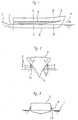
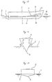
- the former type of high-speed ship is shown in Figs. 15 to 17, and the latter type high-speed ship is shown in Figs. 18 to 19.
- Fig. 15 is a side view
- Fig. 16 is a transverse cross-section view taken along line B-B in Fig. 15
- Fig. 17 is another transverse cross-section view taken along line C-C in Fig.
- Fig. 18 is a side view
- Fig. 19 is a transverse cross-section view taken along line B-B in Fig. 18,
- Fig. 20 is another transverse cross-section view taken along line C-C in Fig. 18.
- reference numeral 1 designates a still water level
- numeral 2 designates a wave creeping up along a hull surface or a spray, which arises from a bow upon navigation
- numeral 3 designates a wave at a stern transom
- numeral 4 designates a traveling direction of the ship
- numeral 5 designates an upper deck
- numeral 6 designates a bottom keel
- numeral 7 designates a chine
- numeral 8 designates a round bilge.
- This phenomenon implies that even if a ship has a sufficient stability at the time of a stationary state, unless it has a stability higher than a certain range, it has a tendency of increasing an instability at a high speed, and this has become clarified to a certain extent as a result of research in recent years.
- Another object of the present invention is to provide a high-speed lateral-stability hull construction provided with reaction flaps formed so as to give a restoring force against large-amplitude rolling.
- Still another object of the present invention is to provide a transom type hull structure provided with efficient reaction flaps having particular shape and structure at particular positions on side platings, which has a large restoring force against rolling and is excellent in high-speed lateral stability.
- a reaction flap having the following construction is employed.
- the reaction flap employed in the hull according to the present invention has a length equal to at least about 10% of a ship length, is provided in the rear of a fore perpendicular of the hull, and also in front of a shoulder of the hull, extends with a rising gradient towards a bow on a side plating, and furthermore, an inner surface formed in cooperation with the side plating is curved in a parabolic shape so that water flow therein may flow smoothly, and has an upset-U-shaped cross-section having a deepest depth of 100 mm or more.
- shoulder of a hull means the position of a side plating where a ship width becomes maximum.
- an inclination angle of the inner surface at its bottom portion is chosen to be outward 45° or less so that a vector component contributing to lateral stability of the hull may be increased by these reaction flaps.
- reaction flaps could be formed so as to have a fixed depth along the lengthwise direction.
- reaction flaps are provided along a chine as directed downwards from the chine so that the provision of the reaction flaps may not reduce a submerged volume of the hull, nor the reaction flaps may not project laterally from the hull resulting in increase of a ship width.
- reaction flaps are provided only from the fore perpendicular of the hull over the shoulder of the hull and thereby lateral stability of the hull is effectively obtained.
- reaction flaps are provided above the water line when the hull is stationary so that a propelling resistance may not be increased even at the time of low-speed navigation.
- the length of the reaction flaps is limited to 10 - 30% of the length of the hull, and thereby a hull construction having high-speed lateral-stability which is practically effective, can be provided.
- reaction flaps extending along side platings from a bow towards a stern and forming an upset-U-shaped cross-section between their inner surfaces and the side platings are provided, the wave or spray rising and falling along the inner surfaces of the reaction flaps would not be discharged outwards directly, but it would once collides against the recess at the top of the upset-U-shaped cross-section of the hull and then would make U-turn in the obliquely downward and outward direction, and consequently, an upward reaction force vector is produced due to a dynamic pressure caused by the collision and a spouting force directed in the downward and outward direction. Since the reaction force vector component acts as a restoring force, lateral stability at the time of high-speed navigation is improved.
- reference numeral 1 designates a water level at the time of stationary state
- numeral 2 designates a wave creeping up along the hull surface or a spray, which arises from a bow at the time of navigation
- numeral 3 designates a wave arising at a stern transom
- numeral 4 designates a traveling direction
- numeral 5 designates an upper deck
- numeral 6 designates a bottom keel
- numeral 9 designates reaction flaps forming upset-U-shaped cross-sections between side platings and them.
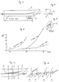
- a maximum width portion exists in the proximity of a stern end, and reaction flaps 9 are provided in the rear of a fore perpendicular along the both side platings of a freeboard above a draught line 1 at the time of stationary state, and extend from a bow towards a stern with a lowering gradient.
- the length of the reaction flaps 9 is chosen to be 1/3 - 1/2 or more of a ship length and the depth d of the deepest portion is chosen to be 300 mm or more.
- a cross-section configuration of the portions formed by the side platings and the reaction flaps 9 is a flared upset-U-shape.
- the inside recess 10 formed by the reaction flap in cooperation with the side plating has an upset-U-shaped cross-section curved in a parabolic shape so that water flow therethrough may flow smoothly.
- an inclination angle ⁇ of the inner surface of the lower end portion of the reaction flap 9 should be chosen to be at least outward 45 degrees or less for the purpose of increasing a downward reaction force vector component 11 contributing to lateral stability.
- reaction flap 9 is effective if its length is about 20% of a ship length and the depth d of the deepest portion is 100 mm or more as illustrated in the third and fourth preferred embodiments which will be described later.
- the recess 10 formed cooperatively by the reaction flap 9 and the side plating of the hull has a maximum width B of the opening at its lower end portion, and the recess 10 has a smooth inner surface whose cross-section has a parabolic shape with its width narrowed gradually towards the top.
- a wave or a spray rising and falling along this inner surface is not directly discharged to the outside of the hull, but it once collides against a recess at the top of the upset-U-shaped cross-section of the hull and makes U-turn obliquely downwards and outwards, and consequently, an upward reaction force vector 11 caused by a dynamic pressure due to the collision and a spouting force directed in the downward and outward direction, is generated. It is important that a reaction force vector 11 is utilized as a restoring force. Therefore, the reaction flaps 9 form a rigid construction.
- the hull construction according to the first preferred embodiment is formed by adding reaction flaps 9 to a hull construction, and hence it is effective for reconstruction of an existing ship
- the hull construction according to the second preferred embodiment is formed by incorporating reaction flaps as a part of the hull construction from the time of initial building of the hull construction.
- reaction flaps 9 directed downwards are provided above a draught line 1 at the time of a stationary state in the proximity of a chine as extending from the neighborhood of a maximum width portion (in a conventional ship type, positioned in front of a 50% point of a ship length).
- the inventor of this invention conducted a tank test with respect to influences of the length of the reaction flaps 9 upon stability of a heel angle of a hull at the time of high-speed navigation, and the following items were clarified.
- reaction flaps 9 of the B type-ship are submerged under a water level from the neighborhood of the maximum width portion (in a conventional ship type, positioned in front of a 50% point of a ship length) at the time of a stationary state.
- reaction flaps 9 are provided only in a bow portion above a draught line 1 at the time of a stationary state as is the case with the A type ship, and also if their length is chosen to be about 1/5 of a ship length (a length of about 10% - 30%) and their depth d is chosen to be d ⁇ 100 mm, then a further good result can be obtained.
- the reaction flaps 9 are provided above the draught line at the time of a stationary state, even upon navigation, a propelling resistance would not be increased.
- the reaction flaps 9 in the bow portion of the third preferred embodiment have their depths d reduced successively towards its rear end as compared to their central portion. This is because with respect to the rear portion, the effects of the reaction flaps cannot be expected so much since the height of the wave creeping up is low and if they are kept deep, they would result in increase of a resistance.
- a length of the reaction flaps 9 is chosen to be about 10% - 30% of a ship length, a depth at the deepest portion is chosen to be about 100 mm or more, and an inclination angle ⁇ of the inner surface of the lower end portion is selected to be outward 45 degrees or less.
- reaction flaps 9 in the bow portion of the fourth preferred embodiment have their depth d successively reduced towards their front end and towards their rear end as compared to their central portion.
- a length of the reaction flaps 9 is chosen to be about 10% - 30% of a ship length, a depth at the deepest portion is chosen to be about 100 mm or more, and an inclination angle ⁇ of the inner surface of their lower end portion is chosen to be outward 45 degrees or less.
- a height of the bow reaction flaps 9 is determined depending upon a magnitude of a spray 2, hence a raw material cost can be minimized, and in the case where the reaction flaps are provided integrally as a part of a hull construction as is the case with the second preferred embodiment, the fourth preferred embodiment is especially effective.
- a high speed can be realized up to the speed region where problems occurred in lateral stability in the case of a heretofore known ship type, or even in the case of the same speed region, a length-to-width ratio can be chosen so as to be more slender, and hence it is possible to reduce a resistance. Furthermore, even in the case of the same speed region and the same length-to-width ratio, it becomes possible to realize an arrangement in which a lateral restoring performance is reduced, that is, a center of gravity is raised.
- first and second preferred embodiments were disclosed for the case where the scope of application of the hanging of the recessed portion of reaction flaps 9 was chosen to be a long region extending from a position near to a bow up to a stern end, in practice, even if it is applied only to the bow portion, provided that its length is about 1/5 times a ship length (a length of about 10% - 30%) similarly to the third and fourth preferred embodiments, a practical advantage is large.
- a high-speed lateral-stability hull construction which is a transom type hull consisting of a single body regardless of whether it is of chine type or of round bilge type, has a small wave making resistance and yet is excellent in lateral stability, and especially which is excellent in lateral stability even in the case of a Froude number of 0.7 or less, and therefore, the present invention is industrially extremely useful.
Landscapes
- Physics & Mathematics (AREA)
- Fluid Mechanics (AREA)
- Ocean & Marine Engineering (AREA)
- Engineering & Computer Science (AREA)
- Combustion & Propulsion (AREA)
- Mechanical Engineering (AREA)
- Chemical & Material Sciences (AREA)
- Other Liquid Machine Or Engine Such As Wave Power Use (AREA)
- Vibration Prevention Devices (AREA)
- Measurement Of Velocity Or Position Using Acoustic Or Ultrasonic Waves (AREA)
- Aerodynamic Tests, Hydrodynamic Tests, Wind Tunnels, And Water Tanks (AREA)
- Prevention Of Electric Corrosion (AREA)
- Helmets And Other Head Coverings (AREA)
Applications Claiming Priority (4)
| Application Number | Priority Date | Filing Date | Title |
|---|---|---|---|
| JP25569592 | 1992-08-31 | ||
| JP255695/92 | 1992-08-31 | ||
| JP5083968A JPH06122390A (ja) | 1992-08-31 | 1993-03-18 | 高速横安定性船体構造 |
| JP83968/93 | 1993-03-18 |
Publications (2)
| Publication Number | Publication Date |
|---|---|
| EP0585698A1 true EP0585698A1 (de) | 1994-03-09 |
| EP0585698B1 EP0585698B1 (de) | 1997-06-25 |
Family
ID=26425003
Family Applications (1)
| Application Number | Title | Priority Date | Filing Date |
|---|---|---|---|
| EP93113025A Expired - Lifetime EP0585698B1 (de) | 1992-08-31 | 1993-08-13 | Schnellschiffsrumpfkonstruktion mit Seitenstabilität |
Country Status (8)
| Country | Link |
|---|---|
| US (1) | US5425325A (de) |
| EP (1) | EP0585698B1 (de) |
| JP (1) | JPH06122390A (de) |
| KR (1) | KR0139040B1 (de) |
| AU (1) | AU661790B2 (de) |
| DE (1) | DE69311771T2 (de) |
| ES (1) | ES2103050T3 (de) |
| SG (1) | SG63542A1 (de) |
Cited By (4)
| Publication number | Priority date | Publication date | Assignee | Title |
|---|---|---|---|---|
| NL1036206C2 (nl) * | 2008-11-17 | 2010-05-18 | Tryvia Boat Patent B V | Snelvarend vaartuig. |
| CN102700680A (zh) * | 2012-06-08 | 2012-10-03 | 中国神华能源股份有限公司 | 排水型引航艇 |
| WO2014200407A1 (en) * | 2013-06-11 | 2014-12-18 | Petestep Ab | A watercraft vessel with a planing hull |
| CN104981395A (zh) * | 2013-01-18 | 2015-10-14 | 代尔夫特科技大学 | 快船 |
Families Citing this family (14)
| Publication number | Priority date | Publication date | Assignee | Title |
|---|---|---|---|---|
| BR9508989A (pt) * | 1994-08-13 | 1997-11-11 | Zhencheng Chen | Embarcação planadora |
| BR9800843A (pt) * | 1998-03-06 | 2000-04-18 | Petroleo Brasileiro Sa | Bolina ad hoc para sistemas de produção de petróleo tipo fpso |
| US6085685A (en) * | 1998-07-27 | 2000-07-11 | Morishige; Tim | Spray deflector for a personal watercraft, jet ski or boat |
| US6805067B1 (en) | 2002-08-14 | 2004-10-19 | The United States Of America As Represented By The Secretary Of The Navy | Contour stern flap |
| US6698370B1 (en) | 2002-08-29 | 2004-03-02 | The United States Of America As Represented By The Secretary Of The Navy | Hydrodynamic and supportive structure for gated ship stern |
| US7320291B2 (en) * | 2005-05-11 | 2008-01-22 | Thomas Eckert | Multi-purpose, plastic molded, sit-on-top kayak |
| US20060254486A1 (en) * | 2005-05-12 | 2006-11-16 | Ashdown Glynn R | Winged hull for a watercraft |
| USD544824S1 (en) | 2006-05-11 | 2007-06-19 | Thomas Eckert | Sit-on-top, multi-purpose kayak, providing a removable back rest, an upper reinforcing ridge, and a continuous, grooved bottom for stability and steering control |
| US8122840B2 (en) * | 2008-07-02 | 2012-02-28 | Harper Justin A | Transom stern hull form and appendages for improved hydrodynamics |
| ES2702705T3 (es) * | 2009-06-16 | 2019-03-05 | Safe Boats Int L L C | Embarcación con casco escalonado y aletas fueraborda |
| US8616142B2 (en) | 2010-08-02 | 2013-12-31 | Lifetime Products, Inc. | Kayak |
| US8800468B2 (en) | 2011-09-22 | 2014-08-12 | Lifetime Products, Inc. | Kayak |
| US9517814B2 (en) | 2013-11-04 | 2016-12-13 | Lifetime Products, Inc. | Adjustable foot brace for watercraft |
| US12600433B2 (en) * | 2023-02-07 | 2026-04-14 | Aspen Power Catamarans Llc | Tender with hybrid catamaran hull configuration |
Citations (5)
| Publication number | Priority date | Publication date | Assignee | Title |
|---|---|---|---|---|
| US3045629A (en) * | 1959-12-11 | 1962-07-24 | Floyd W Farrington | Boat hull |
| US3602179A (en) * | 1970-05-01 | 1971-08-31 | Richard C Cole | Hydroplane boat |
| US3776168A (en) * | 1972-06-09 | 1973-12-04 | Belmont Boats Inc | High speed boat hull |
| US4660490A (en) * | 1986-01-30 | 1987-04-28 | Olympia Sports Products, Inc. | Recreational semi-displacement hull watercraft |
| EP0249321A2 (de) * | 1986-04-24 | 1987-12-16 | Rewi Kemp | Schiffskörper |
Family Cites Families (14)
| Publication number | Priority date | Publication date | Assignee | Title |
|---|---|---|---|---|
| US1505113A (en) * | 1922-10-30 | 1924-08-19 | Gidley Boat Company Ltd | Motor boat |
| US2634698A (en) * | 1941-04-21 | 1953-04-14 | Beckerbat Ab | High-speed motor boat |
| US2919669A (en) * | 1957-07-19 | 1960-01-05 | Shin Meiwa Kogyo Kabushiki Kai | Spray-controller for watercraft |
| US3763810A (en) * | 1972-03-24 | 1973-10-09 | Blade Hulls Inc | High speed boat with planing hull |
| JPS536880B2 (de) * | 1973-05-31 | 1978-03-11 | ||
| DE2829901A1 (de) * | 1978-07-07 | 1980-01-24 | Metallgesellschaft Ag | Verfahren zur herstellung eines bleches oder bandes mit oberflaechiger katalysatorstruktur |
| AU8169882A (en) * | 1981-03-20 | 1982-09-23 | John Patrick Ettridge | Catamaran hulls with side fins |
| FR2522556A1 (en) * | 1981-12-03 | 1983-09-09 | Pimoule Roger | Marine vessel hull with wave propulsion - converts vertical force of sea swell into horizontal force aiding propulsion using grooves on hull |
| JPS613191U (ja) * | 1984-06-13 | 1986-01-10 | 川崎重工業株式会社 | 小型滑走艇 |
| JPS61226389A (ja) * | 1985-03-29 | 1986-10-08 | Nissan Motor Co Ltd | 小型船舶の水飛沫防止装置 |
| US4919063A (en) * | 1988-03-28 | 1990-04-24 | Swath Ocean Systems, Inc. | Hull construction for a swath vessel |
| US5199367A (en) * | 1989-01-31 | 1993-04-06 | Yamaha Hatsudoki Kabushiki Kaisha | Catamaran |
| NO303570B1 (no) * | 1990-11-01 | 1998-08-03 | Ishikawajima Harima Heavy Ind | Skrog |
| US5231945A (en) * | 1991-09-25 | 1993-08-03 | Ackerbloom T Robert | Power boat hull |
-
1993
- 1993-03-18 JP JP5083968A patent/JPH06122390A/ja active Pending
- 1993-08-13 SG SG1996001082A patent/SG63542A1/en unknown
- 1993-08-13 ES ES93113025T patent/ES2103050T3/es not_active Expired - Lifetime
- 1993-08-13 EP EP93113025A patent/EP0585698B1/de not_active Expired - Lifetime
- 1993-08-13 DE DE69311771T patent/DE69311771T2/de not_active Expired - Fee Related
- 1993-08-20 KR KR1019930016198A patent/KR0139040B1/ko not_active Expired - Fee Related
- 1993-08-27 AU AU44958/93A patent/AU661790B2/en not_active Ceased
- 1993-08-30 US US08/113,247 patent/US5425325A/en not_active Expired - Fee Related
Patent Citations (5)
| Publication number | Priority date | Publication date | Assignee | Title |
|---|---|---|---|---|
| US3045629A (en) * | 1959-12-11 | 1962-07-24 | Floyd W Farrington | Boat hull |
| US3602179A (en) * | 1970-05-01 | 1971-08-31 | Richard C Cole | Hydroplane boat |
| US3776168A (en) * | 1972-06-09 | 1973-12-04 | Belmont Boats Inc | High speed boat hull |
| US4660490A (en) * | 1986-01-30 | 1987-04-28 | Olympia Sports Products, Inc. | Recreational semi-displacement hull watercraft |
| EP0249321A2 (de) * | 1986-04-24 | 1987-12-16 | Rewi Kemp | Schiffskörper |
Cited By (9)
| Publication number | Priority date | Publication date | Assignee | Title |
|---|---|---|---|---|
| NL1036206C2 (nl) * | 2008-11-17 | 2010-05-18 | Tryvia Boat Patent B V | Snelvarend vaartuig. |
| WO2010056120A1 (en) * | 2008-11-17 | 2010-05-20 | Tryvia Boat Patent B.V. | High-speed vessel |
| CN102700680A (zh) * | 2012-06-08 | 2012-10-03 | 中国神华能源股份有限公司 | 排水型引航艇 |
| CN102700680B (zh) * | 2012-06-08 | 2015-03-04 | 中国神华能源股份有限公司 | 排水型引航艇 |
| CN104981395A (zh) * | 2013-01-18 | 2015-10-14 | 代尔夫特科技大学 | 快船 |
| CN104981395B (zh) * | 2013-01-18 | 2017-10-31 | 代尔夫特科技大学 | 快船 |
| WO2014200407A1 (en) * | 2013-06-11 | 2014-12-18 | Petestep Ab | A watercraft vessel with a planing hull |
| EP3007964A4 (de) * | 2013-06-11 | 2017-03-08 | Petestep AB | Wasserfahrzeug mit gleiter |
| US10293886B2 (en) | 2013-06-11 | 2019-05-21 | Petestep Ab | Watercraft vessel with a planing hull |
Also Published As
| Publication number | Publication date |
|---|---|
| AU661790B2 (en) | 1995-08-03 |
| DE69311771D1 (de) | 1997-07-31 |
| KR0139040B1 (ko) | 1998-06-01 |
| JPH06122390A (ja) | 1994-05-06 |
| SG63542A1 (en) | 1999-03-30 |
| EP0585698B1 (de) | 1997-06-25 |
| AU4495893A (en) | 1994-03-10 |
| DE69311771T2 (de) | 1997-11-27 |
| US5425325A (en) | 1995-06-20 |
| KR940003805A (ko) | 1994-03-12 |
| ES2103050T3 (es) | 1997-08-16 |
Similar Documents
| Publication | Publication Date | Title |
|---|---|---|
| EP0585698B1 (de) | Schnellschiffsrumpfkonstruktion mit Seitenstabilität | |
| US4231314A (en) | Hydroplane boat | |
| US4606291A (en) | Catamaran with hydrofoils | |
| US3521590A (en) | Ship's bow construction | |
| US6176196B1 (en) | Boat bottom hull design | |
| WO2000007874A1 (en) | Trimaran construction | |
| US5526762A (en) | Power planing catamaran | |
| US5351641A (en) | Boat hull construction | |
| EP0359825B1 (de) | Gleitboot | |
| AU640570B2 (en) | Vessel with improved hydrodynamic performance | |
| JPS61184193A (ja) | ボ−トの底部構造 | |
| US3602179A (en) | Hydroplane boat | |
| US5188049A (en) | Catamaran boat | |
| US5433161A (en) | SWAS vessel | |
| EP0268711B1 (de) | Schiffsrumpfformen | |
| AU2002340764B2 (en) | Boat | |
| JP2837930B2 (ja) | 砕氷船 | |
| RU2238871C2 (ru) | Корпус быстроходного судна | |
| US20030041791A1 (en) | Motorboat with a skimmer hull | |
| US3550550A (en) | Ocean-going barge | |
| GB2058678A (en) | Semi-submersibles | |
| EP0475634B1 (de) | Katamaran-Boot | |
| CN216232818U (zh) | 一种增强横向稳定性的滑行艇船型 | |
| JPH06321172A (ja) | 高速横安定性船体構造 | |
| JP3294517B2 (ja) | 高速艇船体 |
Legal Events
| Date | Code | Title | Description |
|---|---|---|---|
| PUAI | Public reference made under article 153(3) epc to a published international application that has entered the european phase |
Free format text: ORIGINAL CODE: 0009012 |
|
| 17P | Request for examination filed |
Effective date: 19930910 |
|
| AK | Designated contracting states |
Kind code of ref document: A1 Designated state(s): DE ES FR GB IT |
|
| 17Q | First examination report despatched |
Effective date: 19950320 |
|
| GRAG | Despatch of communication of intention to grant |
Free format text: ORIGINAL CODE: EPIDOS AGRA |
|
| GRAH | Despatch of communication of intention to grant a patent |
Free format text: ORIGINAL CODE: EPIDOS IGRA |
|
| GRAH | Despatch of communication of intention to grant a patent |
Free format text: ORIGINAL CODE: EPIDOS IGRA |
|
| GRAA | (expected) grant |
Free format text: ORIGINAL CODE: 0009210 |
|
| AK | Designated contracting states |
Kind code of ref document: B1 Designated state(s): DE ES FR GB IT |
|
| REF | Corresponds to: |
Ref document number: 69311771 Country of ref document: DE Date of ref document: 19970731 |
|
| REG | Reference to a national code |
Ref country code: ES Ref legal event code: FG2A Ref document number: 2103050 Country of ref document: ES Kind code of ref document: T3 |
|
| ET | Fr: translation filed | ||
| PLBE | No opposition filed within time limit |
Free format text: ORIGINAL CODE: 0009261 |
|
| 26N | No opposition filed | ||
| PGFP | Annual fee paid to national office [announced via postgrant information from national office to epo] |
Ref country code: DE Payment date: 20010806 Year of fee payment: 9 |
|
| PGFP | Annual fee paid to national office [announced via postgrant information from national office to epo] |
Ref country code: GB Payment date: 20010808 Year of fee payment: 9 |
|
| PGFP | Annual fee paid to national office [announced via postgrant information from national office to epo] |
Ref country code: FR Payment date: 20010810 Year of fee payment: 9 |
|
| PGFP | Annual fee paid to national office [announced via postgrant information from national office to epo] |
Ref country code: ES Payment date: 20010824 Year of fee payment: 9 |
|
| REG | Reference to a national code |
Ref country code: GB Ref legal event code: IF02 |
|
| PG25 | Lapsed in a contracting state [announced via postgrant information from national office to epo] |
Ref country code: GB Free format text: LAPSE BECAUSE OF NON-PAYMENT OF DUE FEES Effective date: 20020813 |
|
| PG25 | Lapsed in a contracting state [announced via postgrant information from national office to epo] |
Ref country code: ES Free format text: LAPSE BECAUSE OF NON-PAYMENT OF DUE FEES Effective date: 20020814 |
|
| PG25 | Lapsed in a contracting state [announced via postgrant information from national office to epo] |
Ref country code: DE Free format text: LAPSE BECAUSE OF NON-PAYMENT OF DUE FEES Effective date: 20030301 |
|
| GBPC | Gb: european patent ceased through non-payment of renewal fee |
Effective date: 20020813 |
|
| PG25 | Lapsed in a contracting state [announced via postgrant information from national office to epo] |
Ref country code: FR Free format text: LAPSE BECAUSE OF NON-PAYMENT OF DUE FEES Effective date: 20030430 |
|
| REG | Reference to a national code |
Ref country code: FR Ref legal event code: ST |
|
| REG | Reference to a national code |
Ref country code: ES Ref legal event code: FD2A Effective date: 20030912 |
|
| PG25 | Lapsed in a contracting state [announced via postgrant information from national office to epo] |
Ref country code: IT Free format text: LAPSE BECAUSE OF NON-PAYMENT OF DUE FEES;WARNING: LAPSES OF ITALIAN PATENTS WITH EFFECTIVE DATE BEFORE 2007 MAY HAVE OCCURRED AT ANY TIME BEFORE 2007. THE CORRECT EFFECTIVE DATE MAY BE DIFFERENT FROM THE ONE RECORDED. Effective date: 20050813 |