EP0585784A1 - Mehrkoordinaten-Tastmessgerät - Google Patents
Mehrkoordinaten-Tastmessgerät Download PDFInfo
- Publication number
- EP0585784A1 EP0585784A1 EP93113517A EP93113517A EP0585784A1 EP 0585784 A1 EP0585784 A1 EP 0585784A1 EP 93113517 A EP93113517 A EP 93113517A EP 93113517 A EP93113517 A EP 93113517A EP 0585784 A1 EP0585784 A1 EP 0585784A1
- Authority
- EP
- European Patent Office
- Prior art keywords
- housing
- plate
- joint head
- slide
- probe
- Prior art date
- Legal status (The legal status is an assumption and is not a legal conclusion. Google has not performed a legal analysis and makes no representation as to the accuracy of the status listed.)
- Granted
Links
Images

Classifications
-
- G—PHYSICS
- G01—MEASURING; TESTING
- G01B—MEASURING LENGTH, THICKNESS OR SIMILAR LINEAR DIMENSIONS; MEASURING ANGLES; MEASURING AREAS; MEASURING IRREGULARITIES OF SURFACES OR CONTOURS
- G01B5/00—Measuring arrangements characterised by the use of mechanical techniques
- G01B5/004—Measuring arrangements characterised by the use of mechanical techniques for measuring coordinates of points
- G01B5/008—Measuring arrangements characterised by the use of mechanical techniques for measuring coordinates of points using coordinate measuring machines
- G01B5/012—Contact-making feeler heads therefor
Definitions
- the invention relates to a multi-coordinate probe measuring device, with a housing over which a probe arm with a probe ball protrudes axially at the free end, which is axially displaceable in the housing and is supported on this via a ball joint made of an annular seat formed in a housing plate and rotatably supported therein , on the probe arm designed spherical joint head is pivoted on all sides up to a predetermined maximum angle and on which in the housing a slide which is guided against the force of a return spring is supported and which is coupled to a display device indicating the displacement size of the slide, the joint head consisting of the ring seat can be lifted out by the axial displacement of the probe arm and is designed as a spherical section on which a tilting plate is formed which is supported axially with its circular circumferential edge on the slide so as to be tiltable.
- Such a multi-coordinate touch probe is used in particular to set the zero point of a numerically controlled milling machine in relation to the workpiece to be machined.
- the probe measuring device is clamped into the machine spindle and moved with the probe ball up to a reference probe edge of the workpiece. As soon as the display device is in the zero position, the zero point of the relevant coordinate is reached, to which the control of the milling machine can then be set.
- the tilt plate is designed as the upper chord surface of a spherical section forming the joint head, which is larger than a hemisphere, so that the diameter of the chord surface is smaller than the ball diameter and approximately corresponds to the diameter of the ring seat.
- This probe measuring device is only suitable for relatively small pivoting angles of the probe arm, since at larger pivoting angles due to the friction and Force relationships, which act on the joint head in the pivoting positions of the probe arm, the center of the ball of the joint head migrates out of the desired position, which must lead to measurement errors.
- the invention solves the problem of how a multi-coordinate probe measuring device of the type mentioned at the outset can be designed such that, with a simple structure, appropriate precision and functionality can be achieved even with large measuring paths in the axial and radial directions.
- the tilt plate projects radially on all sides beyond the joint head and the plane of the tilt plate extends in the region of the center of curvature of the joint head.
- the probe arm is supported directly on the slide via the tilting plate, as a result of which there are no intermediate joints in the support chain and a direct path transmission from the probe ball to the slide is achieved.
- the radial protrusion of the tilt plate over the joint head and thus over the ring seat for the joint head also creates a counter-moment to that on the joint head in the swivel positions of the probe arm and therefore in the tilt positions of the tilt plate due to the force of the return spring of the caliper acting eccentrically on the tilt plate Torque acting from the push of a button and the lever arm of the touch arm.
- the invention enables a relatively weak design of the return spring of the slide, so that the smoothness of the touch probe is ensured without impairing precision.
- the tilting plate plane continues in the area of the center of curvature of the joint head, the play between the tilting plate and the area surrounding it can cylindrical housing wall as well as radial displacement quantities of the point of contact between the slide and the tilting plate during its tilting movements are kept as small as possible.
- the diameter of the tilting plate does not move out of the diameter of the cylindrical housing when the probe arm is pivoted, so that the diameter of the tilting plate can correspond to the inside diameter of the housing except for a small amount of guide play and the joint head on the peripheral edge of the tilting plate during the axial movements of the probe arm the housing wall is guided.
- the guide play for the tilt plate can be further reduced by rounding the circumferential edge of the tilt plate in a convex manner or so that there is no risk of collision between the upper and the lower peripheral edge on the one hand and the housing wall on the other hand when the tilt plate is tilted even if the tilt plate is of substantial thickness.
- the part of the tilting plate which projects radially beyond the joint head can be conical on the side facing the ring seat, the conical tip being intended is on the side of the tilt plate facing away from the slide.
- the slider preferably has a support plate with the same diameter as the tilting plate, on which the tilting plate rests.
- the support plate can sit on a slide axis, via which the slide is slidably mounted and guided in the housing and on which the return spring engages.
- a coupling element can be provided on the slide axis for transmitting the displacement size of the slide to the display device of the touch probe.
- the display device can be one with the slide be mechanically coupled pointer dial gauge. However, it is also possible to provide a display device coupled, for example, optoelectronically or inductively or the like.
- a tension spring can be clamped between the slide and the joint head in order to favor the resetting of the probe arm from its swivel position into the axial position.
- a precise alignment of the center point of the probe ball on the spindle axis of the milling machine can be achieved in known multi-component touch probes of the present type by radially adjusting the axis of the caliper at a distance from the joint head using four adjusting screws.
- the housing plate receiving the ring seat is axially clamped to the housing via a pressure ring and a plate spring and is held in the pressure ring with circumferential play, and that between the pressure ring and the housing plate is formed an outer axial annular groove for the engagement of a lever tool.
- the radial stroke of the probe ball can be determined with the help of a dial gauge attached to it when the spindle of the milling machine is rotated with the probe measuring device clamped in it, and the housing plate can then be adjusted in the corresponding radial direction relative to the pressure ring and therefore the housing up to concentricity.
- the probe arm can be made in one piece with the joint head, it is preferred to make it interchangeable so that probe arms of different lengths can be used with the same probe measuring device. Therefore, a chuck, preferably a cone chuck, can be formed on the joint head on the side facing away from the housing, in which the probe arm is interchangeably fixed via a shaft, correspondingly preferably a cone shaft.
- a cone seat is particularly preferred because it has a high degree of change accuracy and may therefore make it unnecessary to adjust the concentricity.
- "loose" styli are prevented by a cone seat.
- a cylindrical or preferably conical clamping shaft 16 is formed for clamping the touch probe into the chuck of the milling spindle.
- a cylindrical housing chamber 20 is formed, in which the sensing arm 3 is mounted in an annular seat 5 via a joint head 4 designed as a spherical section, which is formed in the front housing plate 2.
- the joint head 4 carries on its side facing away from the ring seat S a tilting plate 8 which axially abuts a support plate 9 of the slide 6 with its axially projecting peripheral edge 21.
- the center of the ball of the joint head 4 lies in the plane containing the axial peripheral edge 21 of the tilt plate.
- the circumferential edge of the tilting plate 8 is rounded convexly and its largest diameter corresponds to the inside diameter of the housing chamber 20 except for a small amount of guide play.
- the bowl-shaped tilting plate 8 projects radially beyond the joint head 4 and thus the ring seat 5 and is on its radially projecting part the underside facing the ring seat 5 is conical.
- the ratio of the outer diameter of the tilt plate 8 to the ball diameter of the joint head 4 is approximately 1.4 in the embodiment shown and the ratio of the diameter of the ring seat 5 to the ball diameter of the joint head 4 is approximately 0.85.
- the support plate 9 of the slide 6 sits at the lower end of a slide shaft 10, which extends through the upper boundary wall 23 of the lower housing chamber 20 and the upper housing chamber 22 located above it into its upper boundary wall 24 and is guided in the boundary walls 23, 24 in slide bearings 11 .
- a return spring 7 is clamped between the upper boundary wall 24 and a spring plate 12 seated on the slide shaft 10.
- a tension spring 15 is clamped between the slide 6 and the joint head 4.
- the spring plate 12 also forms the coupling element 14 to dial gauge 13.
- the probe arm 3 In the starting position of the probe measuring device shown in FIG. 1, the probe arm 3 is located in the device axis and the axial peripheral edge of the tilting plate 8 lies all around on the lower axial peripheral edge of the support plate 9. Therefore, if an axial reference surface of the workpiece is to be approached, there is a pure axial displacement of the probe arm 3 together with the joint head 4, the tilting plate 8 and the slide 6 against the force of the return spring 7, the tilting plate 8 being axially guided on the wall of the housing chamber 20 becomes.
- the probe arm 3 When approaching lateral reference edges of the workpiece, however, the probe arm 3 is pivoted about the center of the ball of the joint head 4, so that the tilting plate 8 tilts relative to the support plate 9 of the slide 6 and therefore the slide 6 against the force of the return spring 7 and also the tension spring 15 accordingly shifts. This creates a torque under the force acting on the probe ball 3a around the point of the ring seat 5 lying in the effective plane of this force.
- the tilting plate 8 projects radially beyond the ring seat 5 and therefore the current tilting axis of the tilting plate 8, at which the The force of the return spring 7 and the tension spring 15 acts on the tilting plate 8 and thus on the joint head 4, radially on the outside at a distance from the next adjacent point of the ring seat 5, a torque which counteracts the torque mentioned arises. Therefore, the joint head 4 remains in its ring seat 5 with the position of its ball center unchanged, so that there are no axial displacements of the joint head and therefore no measurement errors.
- a cone chuck 17 is formed, in which the probe arm 3 is fixed interchangeably via a cone shaft 18.
- an ejector flange 25 is formed on the probe arm 3, so that the probe arm 3 can be levered out for its replacement by means of a flat-blade screwdriver which is inserted into the gap between the ejector flange 25 and the cone chuck 17.
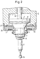
- FIG. 2 largely corresponds to that from FIG. 1. 2, however, the housing plate 2, in which the ring seat 5 is formed for the joint head 4, is held with radial play in a threaded pressure ring 26 which is screwed to the housing 1.
- a plate spring 27 is clamped between the housing plate 2 and the housing 1.
- an outer axial annular gap 28 is present between the pressure ring 26 and the housing plate 2. Therefore, the housing plate 2 and thus the ring seat 5 can be displaced radially with the aid of a tool inserted into the annular gap 28, such as a flat-blade screwdriver, in order to compensate for an eccentricity thereof, measured with a dial gauge on the probe ball 3a, relative to the axis of the probe measuring device.
- the spring force of the plate spring 27 and therefore the frictional engagement between the housing plate 2 and the pressure ring 26 for normal use of the touch probe can be adjusted with the help of the pressure ring 26.
Landscapes
- Physics & Mathematics (AREA)
- General Physics & Mathematics (AREA)
- A Measuring Device Byusing Mechanical Method (AREA)
- Length Measuring Devices With Unspecified Measuring Means (AREA)
- Ultra Sonic Daignosis Equipment (AREA)
- Investigating Or Analyzing Materials By The Use Of Ultrasonic Waves (AREA)
Abstract
Description
- Die Erfindung betrifft ein Mehrkoordinaten-Tastmeßgerät, mit einem Gehäuse, über das ein Tastarm mit einer Tastkugel am freien Ende axial hinaussteht, der in dem Gehäuse axial verschiebbar und an diesem über ein Kugelgelenk aus einem in einer Gehäuseplatte ausgebildeten Ringsitz und einem in diesem drehbar abgestützten, an dem Tastarm ausgebildeten kugeligen Gelenkkopf bis zu einem vorbestimmten Maximalwinkel allseits schwenkbar gelagert ist und auf dem in dem Gehäuse ein gegen die Kraft einer Rückstellfeder geführt verschiebbarer Schieber abgestützt ist, der mit einer die Verschiebegröße des Schiebers anzeigenden Anzeigeeinrichtung gekoppelt ist, wobei der Gelenkkopf aus dem Ringsitz durch die Axialverschiebung des Tastarms aushebbar ist und als Kugelabschnitt ausgebildet ist, auf dem ein Kippteller ausgebildet ist, der mit seinem kreisförmigen Umfangsrand an dem Schieber kippbar axial abgestützt ist.
- Ein derartiges Mehrkoordinaten-Tastmeßgerät dient insbesondere zur Nullpunktseinstellung einer numerisch gesteuerten Fräsmaschine in Bezug auf das zu bearbeitende Werkstück. Hierzu wird das Tastmeßgerät in die Maschinenspindel eingespannt und mit der Tastkugel bis zu einer Bezugsantastkante des Werkstücks verfahren. Sobald die Anzeigeeinrichtung sich in der Nullstellung befindet, ist der Nullpunkt der betreffenden Koordinate erreicht, auf den dann die Steuerung der Fräsmaschine eingestellt werden kann.
- Bei einem bekannten Tastmeßgerät der eingangs erwähnten Art (EP-A-0 332 575) ist der Kippteller als obere Sehnenfläche eines den Gelenkkopf bildenden Kugelabschnitts ausgebildet, der größer als eine Halbkugel ist, so daß der Durchmesser der Sehnenfläche kleiner als der Kugeldurchmesser ist und ungefähr dem Durchmesser des Ringsitzes entspricht. Dieses Tastmeßgerät ist nur für relativ kleine Schwenkwinkel des Tastarms geeignet, da bei größeren Schwenkwinkeln aufgrund der Reibungs- und Kräfteverhältnisse, die in den Schwenkstellungen des Tastarms an dem Gelenkkopf wirken, der Kugelmittelpunkt des Gelenkkopfes aus der Sollstellung auswandert, was zu Meßfehlern führen muß.
- Durch die Erfindung wird das Problem gelöst, wie ein Mehrkoordinaten-Tastmeßgerät der eingangs erwähnten Art derart ausgebildet werden kann, daß bei einfachem Aufbau eine zweckgerechte Präzision und Funktionalität auch bei großen Meßwegen in axialer und in radialer Richtung erreicht werden.
- Dies wird erfindungsgemäß dadurch erreicht, daß der Kippteller über den Gelenkkopf allseits radial hinausragt und die Ebene des Kipptellers im Bereich des Krümmungsmittelpunktes des Gelenkkopfes verläuft.
- Bei dem erfindungsgemäßen Mehrkomponenten-Tastmeßgerät ist der Tastarm über den Kippteller unmittelbar an dem Schieber abgestützt, wodurch Zwischengelenke in der Abstützkette entfallen und eine direkte Wegübertragung von der Tastkugel auf den Schieber erreicht wird. Durch das radiale Vorstehen des Kipptellers über den Gelenkkopf und damit über den Ringsitz für den Gelenkkopf entsteht außerdem in den Schwenkstellungen des Tastarms und daher in den Kippstellungen des Kipptellers aufgrund der auf den Kippteller exzentrisch einwirkenden Kraft der Rückstellfeder des Meßschiebers ein Gegenmoment zu dem auf den Gelenkkopf aus dem Tastdruck und dem Hebelarm des Tastarms einwirkenden Drehmoment. Dies hat zur Folge, daß der Kugelmittelpunkt des Gelenkkopfes und daher die aktuelle Schwenkachse des Tastarms auch bei größeren Schwenkwinkeln nicht auswandern und somit der Gelenkkopf in seiner Lage in dem Ringsitz stabilisiert ist. Weiter ermöglicht die Erfindung eine verhältnismäßig schwache Auslegung der Rückstellfeder des Schiebers, so daß die Leichtgängigkeit des Tastmeßgerätes ohne Präzisionsbeeinträchtigung sichergestellt ist.
- Da weiter die Kipptellerebene im Bereich des Krümmungsmittelpunktes des Gelenkkopfes verläuft, können das Spiel zwischen dem Kippteller und der ihn umgebenden zylindrischen Gehäusewand wie auch radiale Verschiebungsgrößen des Berührungspunktes zwischen dem Schieber und dem Kippteller bei dessen Kippbewegungen möglichst klein gehalten werden. Außerdem wandert dadurch der Durchmesser des Kipptellers beim Verschwenken des Tastarms nicht aus dem Durchmesser des zylindrischen Gehäuses heraus, wodurch der Durchmesser des Kipptellers bis auf ein kleines Führungsspiel dem Innendurchmesser des Gehäuses entsprechen kann und der Gelenkkopf an dem Umfangsrand des Kipptellers bei den Axialbewegungen des Tastarms von der Gehäusewandung geführt wird.
- Das Führungsspiel für den Kippteller kann weiter verkleinert werden, indem der Umfangsrand des Kipptellers konvex abgerundet oder keilförmig gestaltet wird, so daß keine Kollisionsgefahr zwischen der oberen und der unteren Umfangskante einerseits und der Gehäusewandung andererseits beim Verkippen des Kipptellers auch bei wesentlicher Dicke des Kipptellers besteht.
- Damit der freie Schwenkwinkel des Tastarms auch bei verhältnismäßig großem Überstand des Kipptellers über den Gelenkkopf und dennoch kleiner Baugröße des Gehäuses nicht zu klein wird, kann der über den Gelenkkopf radial hinaustehende Teil des Kipptellers an der dem Ringsitz zugewandten Seite kegelförmig sein, wobei die gedachte Kegelspitze an der dem Schieber abgewandten Seite des Kipptellers liegt.
- Vorzugsweise weist der Schieber einen im Durchmesser mit dem Kippteller übereinstimmenden Stützteller auf, an dem der Kippteller anliegt. Der Stützteller kann auf einer Schieberachse sitzen, über welche der Schieber in dem Gehäuse gleitend gelagert und geführt ist und an welcher die Rückstellfeder angreift. Außerdem kann an der Schieberachse ein Kopplungselement zur Übertragung der Verschiebegröße des Schiebers an die Anzeigeeinrichtung des Tastmeßgerätes vorgesehen sein.
- Die Anzeigeeinrichtung kann im übrigen eine mit dem Schieber mechanisch gekoppelte Zeiger-Meßuhr sein. Es ist jedoch auch möglich, eine beispielsweise optoelektronisch oder induktiv oder dergleichen gekoppelte Anzeigeeinrichtung vorzusehen.
- Zusätzlich zu der an dem Meßschieber angreifenden Rückstellfeder kann zwischen dem Schieber und dem Gelenkkopf eine Zugfeder eingespannt sein, um die Rückstellungen des Tastarms aus dessen Schwenkstellungen in die Axialposition zu begünstigen.
- Eine genaue Ausrichtung des Mittelpunktes der Tastkugel auf die Spindelachse der Fräsmaschine läßt sich bei bekannten Mehrkomponenten-Tastmeßgeräten der vorliegenden Art dadurch erreichen, daß die Achse des Meßschiebers im Abstand von dem Gelenkkopf mit Hilfe von vier Justierschrauben radial verstellt wird. In einer Ausgestaltung der Erfindung ist es jedoch auch möglich, die Justierung dadurch zu erreichen, daß die den Ringsitz aufnehmende Gehäuseplatte über einen Druckring und eine Tellerfeder mit dem Gehäuse axial verspannt ist und in dem Druckring mit Umfangsspiel gehalten ist, und daß zwischen dem Druckring und der Gehäuseplatte eine äußere axiale Ringnut für den Eingriff eines Hebelwerkzeugs ausgebildet ist. Mit Hilfe eines geeigneten Werkzeugs, wie eines Schlitzschraubendrehers, ist es daher möglich, die Exzentrizität der Tastkugel gegenüber der Spindelachse dadurch zu beseitigen, daß der Gelenkkopf mittels der den Ringsitz aufnehmenden Gehäuseplatte entsprechend weit radial ausgehebelt wird. Hierzu kann der Radialschlag der Tastkugel mit Hilfe einer an diese angesetzten Meßuhr beim Verdrehen der Spindel der Fräsmaschine mit dem in diese eingespannten Tastmeßgerät festgestellt werden und kann dann die Gehäuseplatte in der entsprechenden Radialrichtung relativ zu dem Druckring und daher dem Gehäuse bis zum Rundlauf verstellt werden. Für eine solche Justierung ist es nicht erforderlich, den Druckring zu lösen, weil der Reibsitz unter der Kraft der Tellerfeder eine lagesichere Stellung der Gehäuseplatte im Normalgebrauch des Tastmeßgerätes bietet. Wenngleich diese Justiermöglichkeit besonders durch die erfindungsgemäße Gestaltung des Tastmeßgerätes gegeben ist, kann sie auch bei andersartigen Mehrkomponenten-Tastmeßgeräten der vorliegenden Art anwendbar sein.
- Wenngleich ferner der Tastarm mit dem Gelenkkopf einstückig hergestellt sein kann, wird es bevorzugt, ihn auswechselbar zu machen, damit Tastarme mit unterschiedlichen Längen mit demselben Tastmeßgerät verwendet werden können. Daher kann an dem Gelenkkopf an der dem Gehäuse abgewandten Seite ein Futter, vorzugsweise ein Konusfutter ausgebildet sein, in welchem der Tastarm über einen Schaft, entsprechend vorzugsweise einen Konusschaft, auswechselbar festgelegt ist. Ein solcher Konussitz wird insbesondere bevorzugt, weil er eine hohe Wechselgenauigkeit aufweist und daher ggf. eine Rundlaufjustierung entbehrlich macht. Außerdem werden durch einen Konussitz "lose" Tasteinsätze verhindert. Wenngleich auch dieser erfindungsgemäße Vorschlag allgemein bei Mehrkoordinaten-Tastmeßgeräten der vorliegenden Art angewendet werden kann, wird die auswechselbare Verwendung auch längerer Tastarme durch deren erfindungsgemäße Lagerung besonders begünstigt, weil die oben geschilderte Kompensation des auf den Gelenkkopf in den Schwenkstellungen des Tastarms exzentrisch einwirkenden Drehmomentes, das mit der Länge des Tastarms zunimmt, durch das über den Kippteller auf den Gelenkkopf einwirkende Gegenmoment begünstigt wird.
- Die Erfindung wird anhand zweier Ausführungsbeispiele erläutert, die wenigstens schematisch aus der Zeichnung ersichtlich sind. In der Zeichnung zeigt:
- Fig. 1 einen Längsschnitt durch ein erfindungsgemäßes Mehrkoordinaten-Tastmeßgerät, und
- Fig. 2 einen Teillängsschnitt durch ein modifiziertes erfindungsgemäßes Mehrkoordinaten-Tastmeßgerät im Bereich der Lagerung des Gelenkkopfes.
- Das Mehrkomponenten-Tastmeßgerät nach Fig. 1 weist einen Tastarm 3 mit einer Tastkugel 3a am freien Ende auf, der in dem Gehäuse 1 an einem Schieber 6 abgestützt ist, dessen Verschiebungsgroße über ein Koppelelement 14 auf eine Meßuhr 13 übertragen und von dieser angezeigt wird.
- Oben auf dem Gehäuse 1 ist ein zylindrischer oder vorzugsweise konischer Einspannschaft 16 zum Einspannen des Tastmeßgerätes in das Futter der Frässpindel ausgebildet. Im unteren Teil des Gehäuses 1 ist eine zylindrische Gehäusekammer 20 ausgebildet, in welcher der Tastarm 3 über einen als Kugelabschnitt ausgebildeten Gelenkkopf 4 in einem Ringsitz 5 gelagert ist, der in der stirnseitigen Gehäuseplatte 2 ausgebildet ist. Der Gelenkkopf 4 trägt an seiner dem Ringsitz S abgewandten Seite einen Kippteller 8, der mit seinem axial abstehenden Umfangsrand 21 axial an einem Stützteller 9 des Schiebers 6 anliegt. Der Kugelmittelpunkt des Gelenkkopfes 4 liegt in der den axialen Umfangsrand 21 des Kipptellers enthaltenden Ebene. Der Umfangsrand des Kipptellers 8 ist konvex abgerundet und entspricht in seinem größten Durchmesser bis auf ein kleines Führungsspiel dem Innendurchmesser der Gehäusekammer 20. Der schüsselförmige Kippteller 8 ragt über den Gelenkkopf 4 und damit den Ringsitz 5 allseits radial hinaus und ist an seinem radial vorstehenden Teil an der dem Ringsitz 5 zugewandten Unterseite kegelförmig ausgebildet. Das Verhältnis des Außendurchmessers des Kipptellers 8 zum Kugeldurchmesser des Gelenkkopfes 4 beträgt bei der dargestellten Ausführungsform etwa 1,4 und das Verhältnis des Durchmessers des Ringsitzes 5 zu dem Kugeldurchmesser des Gelenkkopfes 4 etwa 0,85.
- Der Stützteller 9 des Schiebers 6 sitzt am unteren Ende eines Schieberschaftes 10, der durch die obere Begrenzungswand 23 der unteren Gehäusekammer 20 und die darüber befindliche obere Gehäusekammer 22 bis in deren obere Begrenzungswand 24 verläuft und in den Begrenzungswänden 23, 24 in Gleitlagern 11 geführt ist. Zwischen der oberen Begrenzungswand 24 und einem auf dem Schieberschaft 10 sitzenden Federteller 12 ist eine Rückstellfeder 7 eingespannt. Außerdem ist zwischen dem Schieber 6 und dem Gelenkkopf 4 eine Zugfeder 15 eingespannt. Der Federteller 12 bildet gleichzeitig das Kopplungselement 14 zur Meßuhr 13.
- In der in Fig. 1 gezeigten Ausgangsstellung des Tastmeßgerätes befindet sich der Tastarm 3 in der Geräteachse und der axiale Umfangsrand des Kipptellers 8 liegt ringsum an dem unteren axialen Umfangsrand des Stütztellers 9 an. Soll daher eine axiale Bezugsfläche des Werkstücks angefahren werden, so erfolgt eine reine Axialverschiebung des Tastarms 3 zusammen mit dem Gelenkkopf 4, dem Kippteller 8 und dem Schieber 6 gegen die Kraft der Rückstellfeder 7, wobei der Kippteller 8 an der Wandung der Gehäusekammer 20 axial geführt wird. Beim Anfahren von seitlichen Bezugskanten des Werkstücks hingegen wird der Tastarm 3 um den Kugelmittelpunkt des Gelenkkopfes 4 geschwenkt, so daß der Kippteller 8 gegenüber dem Stützteller 9 des Schiebers 6 verkippt und daher den Schieber 6 gegen die Kraft der Rückstellfeder 7 und auch der Zugfeder 15 entsprechend verschiebt. Dabei entsteht unter der auf die Tastkugel 3a einwirkenden Kraft ein Drehmoment um die in der Wirkungsebene dieser Kraft liegende Stelle des Ringsitzes 5. Dadurch jedoch, daß der Kippteller 8 über den Ringsitz 5 radial hinausragt und daher die aktuelle Kippachse des Kipptellers 8, an der die Kraft der Rückstellfeder 7 und der Zugfeder 15 auf den Kippteller 8 und damit den Gelenkkopf 4 einwirkt, radial außen im Abstand von der nächstbenachbarten Stelle des Ringsitzes 5 liegt, entsteht ein dem erwähnten Drehmoment entgegenwirkendes Drehmoment. Daher bleibt der Gelenkkopf 4 mit unveränderter Lage seines Kugelmittelpunktes in seinem Ringsitz 5, so daß es nicht zu Axialverlagerungen des Gelenkkopfes und daher nicht zu Meßfehlern kommt.
- An der unteren Seite des Gelenkkopfes 4 ist ein Konusfutter 17 ausgebildet, in welchem der Tastarm 3 über einen Konusschaft 18 auswechselbar festgelegt ist. Unter dem Konusschaft 18 ist an dem Tastarm 3 ein Auswerferflansch 25 ausgebildet, so daß der Tastarm 3 mittels eines Schlitzschraubendrehers, der in den Spalt zwischen dem Auswerferflansch 25 und dem Konusfutter 17 eingeführt wird, für sein Auswechseln ausgehebelt werden kann.
- Die Ausführungsform nach Fig. 2 stimmt weitgehend mit der aus Fig. 1 überein. Nach Fig. 2 ist jedoch die Gehäuseplatte 2, in der der Ringsitz 5 für den Gelenkkopf 4 ausgebildet ist, mit Radialspiel in einem Gewindedruckring 26 gehalten, der mit dem Gehäuse 1 verschraubt ist. Zwischen der Gehäuseplatte 2 und dem Gehäuse 1 ist eine Tellerfeder 27 eingespannt. Außerdem ist zwischen dem Druckring 26 und der Gehäuseplatte 2 ein äußerer axialer Ringspalt 28 vorhanden. Daher kann die Gehäuseplatte 2 und somit der Ringsitz 5 mithilfe eines in den Ringspalt 28 eingeführten Werkzeuges, wie eines Schlitzschraubendrehers, radial verschoben werden, um eine mit einer Meßuhr an der Tastkugel 3a gemessene Exzentrizität derselben gegenüber der Achse des Tastmeßgerätes zu kompensieren. Die Federkraft der Tellerfeder 27 und daher der Reibschluß zwischen der Gehäuseplatte 2 und dem Druckring 26 für den normalen Gebrauch des Tastmeßgerätes können mit Hilfe des Druckringes 26 eingestellt werden.
Claims (7)
- Mehrkoordinaten-Tastmeßgerät, mit einem Gehäuse (1), über das ein Tastarm (3) mit einer Tastkugel (3a) am freien Ende axial hinaussteht, der in dem Gehäuse (1) axial verschiebbar und an diesem über ein Kugelgelenk aus einem in einer Gehäuseplatte (2) ausgebildeten Ringsitz (5) und einem in diesem drehbar abgestützten, an dem Tastarm (3) ausgebildeten kugeligen Gelenkkopf (4) bis zu einem vorbestimmten Maximalwinkel allseits schwenkbar gelagert ist und auf dem in dem Gehäuse (1) ein gegen die Kraft einer Rückstellfeder (7) geführt verschiebbarer Schieber (6) abgestützt ist, der mit einer die Verschiebegröße des Schiebers (6) anzeigenden Anzeigeeinrichtung (13) gekoppelt ist, wobei der Gelenkkopf (4) aus dem Ringsitz (5) durch die Axialverschiebung des Tastarms (3) aushebbar und als Kugelabschnitt ausgebildet ist, auf dem ein Kippteller (8) ausgebildet ist, der mit seinem kreisförmigen Umfangsrand an dem Schieber (6) kippbar axial abgestützt ist, dadurch gekennzeichnet, daß der Kippteller (8) über den Gelenkkopf (4) allseits radial hinausragt und die Ebene des Kipptellers (8) im Bereich des Krümmungsmittelpunktes des Gelenkkopfes (4) verläuft.
- Tastmeßgerät nach Anspruch 1, dadurch gekennzeichnet, daß der über den Gelenkkopf (4) radial hinaustehende Teil des Kipptellers (8) an der dem Ringsitz (5) zugewandten Seite kegelförmig ist.
- Tastmeßgerät nach Anspruch 1 oder 2, dadurch gekennzeichnet, daß der Schieber (6) einen im Durchmesser mit dem Kippteller (8) übereinstimmenden Stützteller (9) aufweist, an dem der Kippteller (8) mit seinem axialen Umfangsrand (21) anliegt.
- Tastmeßgerät nach Anspruch 3, dadurch gekennzeichnet, daß der Stützteller (9) an einem Schieberschaft (10) sitzt, an dem der Schieber (6) in dem Gehäuse (1) über Gleitlager (11) geführt ist.
- Tastmeßgerät nach einem der Ansprüche 1 bis 4, dadurch gekennzeichnet, daß zwischen dem Schieber (6) und dem Gelenkkopf (4) eine Zugfeder (15) eingespannt ist
- Tastmeßgerät nach einem der Ansprüche 1 bis 5, dadurch gekennzeichnet, daß die den Ringsitz (5) aufnehmende Gehäuseplatte (2) über einen Druckring (26) und eine Tellerfeder (27) mit dem Gehäuse (1) verspannt ist und in dem Druckring (26) mit Umfangsspiel gehalten ist, und daß zwischen dem Druckring (26) und der Gehäuseplatte (2) ein äußerer Ringspalt (28) für den Eingriff eines Hebelwerkzeugs ausgebildet ist.
- Tastmeßgerät nach einem der Ansprüche 1 bis 6, dadurch gekennzeichnet, daß an dem Gelenkkopf (4) an der dem Gehäuse (1) abgewandten Seite ein Konusfutter (17) ausgebildet ist, in welchem der Tastarm (3) über einen Konusschaft (18) auswechselbar festgelegt ist.
Applications Claiming Priority (2)
| Application Number | Priority Date | Filing Date | Title |
|---|---|---|---|
| DE4228018 | 1992-08-24 | ||
| DE4228018A DE4228018C2 (de) | 1992-08-24 | 1992-08-24 | Mehrkoordinaten-Tastmeßgerät |
Publications (2)
| Publication Number | Publication Date |
|---|---|
| EP0585784A1 true EP0585784A1 (de) | 1994-03-09 |
| EP0585784B1 EP0585784B1 (de) | 1995-04-26 |
Family
ID=6466255
Family Applications (1)
| Application Number | Title | Priority Date | Filing Date |
|---|---|---|---|
| EP93113517A Expired - Lifetime EP0585784B1 (de) | 1992-08-24 | 1993-08-24 | Mehrkoordinaten-Tastmessgerät |
Country Status (7)
| Country | Link |
|---|---|
| US (1) | US5394618A (de) |
| EP (1) | EP0585784B1 (de) |
| JP (1) | JP2576022B2 (de) |
| AT (1) | ATE121834T1 (de) |
| DE (2) | DE4228018C2 (de) |
| ES (1) | ES2071523T3 (de) |
| TW (1) | TW221385B (de) |
Families Citing this family (12)
| Publication number | Priority date | Publication date | Assignee | Title |
|---|---|---|---|---|
| DE19517215C1 (de) * | 1995-05-11 | 1997-02-06 | Heidenhain Gmbh Dr Johannes | Mehrkoordinaten-Tastkopf |
| IT1305536B1 (it) * | 1998-09-21 | 2001-05-09 | Marposs Spa | Testata per il controllo di dimensioni lineari di pezzi meccanici |
| DE19931226C2 (de) * | 1999-07-06 | 2001-10-18 | Mahr Gmbh | Führungssystem für einen Taster und Tastsystem |
| US7024786B2 (en) * | 2001-06-18 | 2006-04-11 | Franz Haimer Maschinenbau Kg | Multi-coordinate sensing measuring device |
| GB0201845D0 (en) * | 2002-01-26 | 2002-03-13 | Renishaw Plc | Analogue probe |
| DE102004035926A1 (de) * | 2004-07-23 | 2006-03-16 | Dr. Johannes Heidenhain Gmbh | Tastkopf |
| CN101352816B (zh) * | 2008-09-08 | 2010-06-02 | 叶仲和 | 双球式寻边表的结构 |
| DE102011056736B4 (de) * | 2011-12-21 | 2016-02-18 | Tschorn Gmbh | Kompaktes 3D-Tastmessgerät |
| CN107869977B (zh) * | 2017-11-23 | 2019-10-22 | 深圳力合精密装备科技有限公司 | 一种坐标测量机测针夹持与调整机构 |
| CN108942411B (zh) * | 2018-07-11 | 2020-04-14 | 南京工程学院 | 一种基于球头万向节的3d寻边器 |
| CN112649045B (zh) * | 2020-12-18 | 2023-07-28 | 南方电网海南数字电网研究院有限公司 | 一种输电线路的监测装置 |
| CN114993222A (zh) * | 2021-03-01 | 2022-09-02 | 桂林市晶瑞传感技术有限公司 | 测量装置 |
Citations (4)
| Publication number | Priority date | Publication date | Assignee | Title |
|---|---|---|---|---|
| FR2375580A1 (fr) * | 1976-12-24 | 1978-07-21 | Rolls Royce | Sonde pour appareils de mesure |
| EP0346562A1 (de) * | 1988-04-26 | 1989-12-20 | Dr. Johannes Heidenhain GmbH | Vorrichtung zur induktiven Signalübertragung bei Tastköpfen |
| WO1991010887A2 (en) * | 1990-01-16 | 1991-07-25 | British Technology Group Ltd. | Probes |
| WO1991014149A1 (en) * | 1990-03-06 | 1991-09-19 | Marposs Società per Azioni | Probe for checking linear dimensions |
Family Cites Families (6)
| Publication number | Priority date | Publication date | Assignee | Title |
|---|---|---|---|---|
| US3250012A (en) * | 1963-02-01 | 1966-05-10 | Lockheed Aircraft Corp | Inspection device and method |
| US3660906A (en) * | 1969-03-17 | 1972-05-09 | Aerojet General Co | Three-axis inspection probe |
| DE2259091A1 (de) * | 1972-12-02 | 1974-06-06 | Volkswagenwerk Ag | Verfahren und tastkopf zur konturenvermessung |
| DE3623614A1 (de) * | 1986-07-12 | 1988-01-14 | Zeiss Carl Fa | Koordinatenmessgeraet mit einem tastkopf vom schaltenden typ |
| CH674485A5 (de) * | 1988-03-11 | 1990-06-15 | Saphirwerk Ind Prod | |
| GB9114945D0 (en) * | 1991-07-11 | 1991-08-28 | Renishaw Metrology Ltd | Touch probe |
-
1992
- 1992-08-24 DE DE4228018A patent/DE4228018C2/de not_active Expired - Lifetime
-
1993
- 1993-08-10 TW TW082106409A patent/TW221385B/zh not_active IP Right Cessation
- 1993-08-20 JP JP5206475A patent/JP2576022B2/ja not_active Expired - Lifetime
- 1993-08-24 ES ES93113517T patent/ES2071523T3/es not_active Expired - Lifetime
- 1993-08-24 DE DE59300158T patent/DE59300158D1/de not_active Expired - Fee Related
- 1993-08-24 US US08/111,124 patent/US5394618A/en not_active Expired - Fee Related
- 1993-08-24 AT AT93113517T patent/ATE121834T1/de not_active IP Right Cessation
- 1993-08-24 EP EP93113517A patent/EP0585784B1/de not_active Expired - Lifetime
Patent Citations (4)
| Publication number | Priority date | Publication date | Assignee | Title |
|---|---|---|---|---|
| FR2375580A1 (fr) * | 1976-12-24 | 1978-07-21 | Rolls Royce | Sonde pour appareils de mesure |
| EP0346562A1 (de) * | 1988-04-26 | 1989-12-20 | Dr. Johannes Heidenhain GmbH | Vorrichtung zur induktiven Signalübertragung bei Tastköpfen |
| WO1991010887A2 (en) * | 1990-01-16 | 1991-07-25 | British Technology Group Ltd. | Probes |
| WO1991014149A1 (en) * | 1990-03-06 | 1991-09-19 | Marposs Società per Azioni | Probe for checking linear dimensions |
Also Published As
| Publication number | Publication date |
|---|---|
| DE4228018A1 (de) | 1994-03-03 |
| EP0585784B1 (de) | 1995-04-26 |
| US5394618A (en) | 1995-03-07 |
| TW221385B (de) | 1994-03-01 |
| JP2576022B2 (ja) | 1997-01-29 |
| DE59300158D1 (de) | 1995-06-01 |
| ES2071523T3 (es) | 1995-06-16 |
| DE4228018C2 (de) | 1994-11-24 |
| ATE121834T1 (de) | 1995-05-15 |
| JPH06185914A (ja) | 1994-07-08 |
Similar Documents
| Publication | Publication Date | Title |
|---|---|---|
| EP0332575B1 (de) | Taster zur Messwertbildung beim Antasten eines Werkstückes | |
| EP2493647B1 (de) | Feindrehwerkzeug | |
| EP0585784B1 (de) | Mehrkoordinaten-Tastmessgerät | |
| DE3508396C1 (de) | Mehrkoordinaten-Tastkopf | |
| DE3320127A1 (de) | Taststiftwechselhalter | |
| DE4100323C2 (de) | Mehrkoordinaten-Tastmeßgerät | |
| DE102016012536B4 (de) | Prüfmaschine und Werkzeug hierfür | |
| CH672838A5 (de) | ||
| EP0270721B1 (de) | Messvorrichtung zur Ermittlung der Abmessungen eines Gegenstandes in drei Dimensionen | |
| DE69413041T2 (de) | Messaufnehmer zur kontrolle von linearen grössen | |
| EP0517653A1 (de) | Tastmesskopf | |
| DE3808548A1 (de) | Messvorrichtung zur lagebestimmung von werkstueck-flaechen | |
| DE4100396C2 (de) | Tastmeßgerät | |
| DE2721157C3 (de) | Druckmesserlehre | |
| DE29612475U1 (de) | Tastkopf | |
| EP0237905B1 (de) | Messeinrichtung zur Ermittlung des Hüllzylinders von Präzisionsrundteilen | |
| WO1998021548A1 (de) | Messvorrichtung | |
| DE3422161C2 (de) | ||
| DE1235005B (de) | Durchmesserlehre fuer Innen- und Aussenmessungen | |
| DE3500050A1 (de) | Messkopf fuer schleifmaschinen | |
| DE9218487U1 (de) | Mehrkoordinaten-Tastmeßgerät | |
| DE2946271A1 (de) | Messkopf fuer eine messmaschine | |
| DE19534338C1 (de) | Feinmeßgerät mit auswechselbaren Meßeinsätzen | |
| DE102005060104B4 (de) | Kompensationsverfahren für eine CNC-Bearbeitungsmaschine | |
| DE9316783U1 (de) | Gewindemeßeinrichtung zur Messung der Einschraubtiefe von Gewinden |
Legal Events
| Date | Code | Title | Description |
|---|---|---|---|
| PUAI | Public reference made under article 153(3) epc to a published international application that has entered the european phase |
Free format text: ORIGINAL CODE: 0009012 |
|
| AK | Designated contracting states |
Kind code of ref document: A1 Designated state(s): AT CH DE ES FR GB IT LI SE |
|
| 17P | Request for examination filed |
Effective date: 19940308 |
|
| 17Q | First examination report despatched |
Effective date: 19940518 |
|
| RAP1 | Party data changed (applicant data changed or rights of an application transferred) |
Owner name: HAFF & SCHNEIDER GMBH & CO. OHG |
|
| GRAA | (expected) grant |
Free format text: ORIGINAL CODE: 0009210 |
|
| AK | Designated contracting states |
Kind code of ref document: B1 Designated state(s): AT CH DE ES FR GB IT LI SE |
|
| REF | Corresponds to: |
Ref document number: 121834 Country of ref document: AT Date of ref document: 19950515 Kind code of ref document: T |
|
| ITF | It: translation for a ep patent filed | ||
| REF | Corresponds to: |
Ref document number: 59300158 Country of ref document: DE Date of ref document: 19950601 |
|
| REG | Reference to a national code |
Ref country code: ES Ref legal event code: FG2A Ref document number: 2071523 Country of ref document: ES Kind code of ref document: T3 |
|
| GBT | Gb: translation of ep patent filed (gb section 77(6)(a)/1977) |
Effective date: 19950612 |
|
| ET | Fr: translation filed | ||
| PLBE | No opposition filed within time limit |
Free format text: ORIGINAL CODE: 0009261 |
|
| 26N | No opposition filed | ||
| REG | Reference to a national code |
Ref country code: GB Ref legal event code: IF02 |
|
| PGFP | Annual fee paid to national office [announced via postgrant information from national office to epo] |
Ref country code: GB Payment date: 20020731 Year of fee payment: 10 |
|
| PGFP | Annual fee paid to national office [announced via postgrant information from national office to epo] |
Ref country code: FR Payment date: 20020819 Year of fee payment: 10 |
|
| PGFP | Annual fee paid to national office [announced via postgrant information from national office to epo] |
Ref country code: AT Payment date: 20020822 Year of fee payment: 10 |
|
| PGFP | Annual fee paid to national office [announced via postgrant information from national office to epo] |
Ref country code: SE Payment date: 20020823 Year of fee payment: 10 |
|
| PGFP | Annual fee paid to national office [announced via postgrant information from national office to epo] |
Ref country code: DE Payment date: 20021031 Year of fee payment: 10 |
|
| PG25 | Lapsed in a contracting state [announced via postgrant information from national office to epo] |
Ref country code: GB Free format text: LAPSE BECAUSE OF NON-PAYMENT OF DUE FEES Effective date: 20030824 Ref country code: AT Free format text: LAPSE BECAUSE OF NON-PAYMENT OF DUE FEES Effective date: 20030824 |
|
| PG25 | Lapsed in a contracting state [announced via postgrant information from national office to epo] |
Ref country code: SE Free format text: LAPSE BECAUSE OF NON-PAYMENT OF DUE FEES Effective date: 20030825 |
|
| PG25 | Lapsed in a contracting state [announced via postgrant information from national office to epo] |
Ref country code: DE Free format text: LAPSE BECAUSE OF NON-PAYMENT OF DUE FEES Effective date: 20040302 |
|
| EUG | Se: european patent has lapsed | ||
| GBPC | Gb: european patent ceased through non-payment of renewal fee | ||
| PG25 | Lapsed in a contracting state [announced via postgrant information from national office to epo] |
Ref country code: FR Free format text: LAPSE BECAUSE OF NON-PAYMENT OF DUE FEES Effective date: 20040430 |
|
| REG | Reference to a national code |
Ref country code: FR Ref legal event code: ST |
|
| PGFP | Annual fee paid to national office [announced via postgrant information from national office to epo] |
Ref country code: ES Payment date: 20100830 Year of fee payment: 18 Ref country code: CH Payment date: 20100825 Year of fee payment: 18 |
|
| PGFP | Annual fee paid to national office [announced via postgrant information from national office to epo] |
Ref country code: IT Payment date: 20100826 Year of fee payment: 18 |
|
| REG | Reference to a national code |
Ref country code: CH Ref legal event code: PL |
|
| PG25 | Lapsed in a contracting state [announced via postgrant information from national office to epo] |
Ref country code: LI Free format text: LAPSE BECAUSE OF NON-PAYMENT OF DUE FEES Effective date: 20110831 Ref country code: CH Free format text: LAPSE BECAUSE OF NON-PAYMENT OF DUE FEES Effective date: 20110831 |
|
| PG25 | Lapsed in a contracting state [announced via postgrant information from national office to epo] |
Ref country code: IT Free format text: LAPSE BECAUSE OF NON-PAYMENT OF DUE FEES Effective date: 20110824 |
|
| REG | Reference to a national code |
Ref country code: ES Ref legal event code: FD2A Effective date: 20130530 |
|
| PG25 | Lapsed in a contracting state [announced via postgrant information from national office to epo] |
Ref country code: ES Free format text: LAPSE BECAUSE OF NON-PAYMENT OF DUE FEES Effective date: 20110825 |