EP0585840A1 - Canon à électrons à effet de champ muni d'une lentille à immersion permettant de réduire l'aberration d'une lentille électrostatique - Google Patents
Canon à électrons à effet de champ muni d'une lentille à immersion permettant de réduire l'aberration d'une lentille électrostatique Download PDFInfo
- Publication number
- EP0585840A1 EP0585840A1 EP93113752A EP93113752A EP0585840A1 EP 0585840 A1 EP0585840 A1 EP 0585840A1 EP 93113752 A EP93113752 A EP 93113752A EP 93113752 A EP93113752 A EP 93113752A EP 0585840 A1 EP0585840 A1 EP 0585840A1
- Authority
- EP
- European Patent Office
- Prior art keywords
- magnetic field
- electron gun
- electrostatic lens
- magnetic
- electron beam
- Prior art date
- Legal status (The legal status is an assumption and is not a legal conclusion. Google has not performed a legal analysis and makes no representation as to the accuracy of the status listed.)
- Granted
Links
Images




Classifications
-
- H—ELECTRICITY
- H01—ELECTRIC ELEMENTS
- H01J—ELECTRIC DISCHARGE TUBES OR DISCHARGE LAMPS
- H01J37/00—Discharge tubes with provision for introducing objects or material to be exposed to the discharge, e.g. for the purpose of examination or processing thereof
- H01J37/02—Details
- H01J37/04—Arrangements of electrodes and associated parts for generating or controlling the discharge, e.g. electron-optical arrangement or ion-optical arrangement
- H01J37/06—Electron sources; Electron guns
- H01J37/073—Electron guns using field emission, photo emission, or secondary emission electron sources
-
- H—ELECTRICITY
- H01—ELECTRIC ELEMENTS
- H01J—ELECTRIC DISCHARGE TUBES OR DISCHARGE LAMPS
- H01J2237/00—Discharge tubes exposing object to beam, e.g. for analysis treatment, etching, imaging
- H01J2237/06—Sources
- H01J2237/063—Electron sources
- H01J2237/06308—Thermionic sources
- H01J2237/06316—Schottky emission
Definitions
- the present invention relates to an improvement of a field emission electron gun systems which are used in electron beam applied apparatus such as a scanning electron microscope (SEM), an electron beam exposure device, a size measuring scanning electron microscope, and the like, using an electron beam, and more particularly relates to an improvement of a magnetic immersion field emission electron gun which is used in the electron beam applied apparatus and capable of reducing an aberration of an electrostatic lens by focusing an electron beam by means of a superposition of a magnetic field over an electrostatic lens system.
- SEM scanning electron microscope
- an electron gun assumes an important part for generating electron beam. Recently, there becomes to be used an electric field emission type electron gun which has the high luminance in comparison with a conventional hot cathode.
- a tip of a cathode in the electric field emission type electron gun is formed in an extremely small needle shape (a radius on or less than 1 ⁇ m), and an electron is radially emitted from the cathode. Since a large opening angle of the beam needs to obtain a large current, a beam diameter is caused to be extended because of a spherical aberration of an electrostatic lens system provided in the electron gun, thereby reducing a luminance. Accordingly, a magnetic field superposes over the electrostatic lens system including the cathode to focus the electron beam to thus decrease an aberration of the electrostatic lens.
- An electron gun having such a construction is called as a magnetic immersion field emission electron gun system.
- FIG. 1 is a section view showing an example of a conventional magnetic immersion field emission electron gun.
- the electron gun is a three-electrode field emission type electron gun which comprises a cathode 101, a first anode 102, and a second anode 103.
- the second anode 103 is connected with a vacuum vessel 104 to be grounded.
- a power source 105 supplies to the cathode 101 with an acceleration voltage which is negative to the vacuum vessel 104.
- the cathode 101 is heated by a power source 107.
- the first anode 102 is connected to a power source 106 to be positive voltage to the cathode 101.
- a single-pole magnetic field lens 108 is provided outside the vacuum vessel 104 to superpose a magnetic field over the electron gun.
- the single-pole magnetic field lens 108 comprises a coil 109 for generating a magnetic flux, and a magnetic substance 110 for forming a magnetic path.
- the electrostatic lens system of the conventionally used magnetic immersion field emission electron gun is a two-polar electron gun comprising a cathode and an anode, or a three-polar electron gun comprising a cathode, a first anode and a second anode. Since these electron guns configured above have a little number of polar and short length of the entire electron gun (a distance from the cathode to the anode), the magnetic superposition near the cathode contributes to a reduction of a spherical aberration.
- the necessity since the necessity happens to independently set an emission current and cross-over position (a focal point) in the electron beam applied apparatus, the necessity starts the use of the electron gun which independently has a leader electrode and a lens electrode, wherein the leader electrode determines an emission current and the lens electrode determines the cross-over position.
- the electron gun is comprised of a four-polar construction having a cathode, a leader electrode, a lens electrode, and an anode, it is impossible for the conventional magnetic immersion field emission electron gun superposing the magnetic field near the cathode to sufficiently reduce the spherical aberration.
- an electron beam gun disclosed in the official gazette of Japanese patent laid-open number Heisei 2-37651 (1990), which comprises a cathode and three-polar portion of a first to third polar
- a permanent magnet generating a magnetic field for reducing a diameter of an electron beam, which is arranged near a passing hole of the electron beam of the second electrode and within a thickness range of the axial direction of the second electrode
- the permanent magnet is arranged in a groove of the second electrode which is formed in U-shape in section, and the magnetic field generated by the permanent magnet makes a flux size of the electron beam be slender for improving a spherical aberration of a main lens.
- an object of the present invention is to provide a magnetic immersion field emission electron gun for superposing a magnetic field in the manner that the superposition of the magnetic field of eliminating a level difference between the image data makes an aberration of an electrostatic lens system included in the magnetic immersion field emission electron gun.
- a magnetic immersion field emission electron gun comprises a vacuum vessel having a cylindrical body, a cathode arranged along the center axis of the vacuum vessel for generating an electron beam, an anode for forming an electron beam path by accelerating the generated electron beam along the direction of the central axis, an electrostatic lens arranged between the cathode and the anode for generating an electric field which focuses the accelerated electron beam into the central axis, magnetic field generating means arranged around the electron beam path for focusing the electron beam in order to reduce an aberration of the electrostatic lens, moving means for moving the magnetic field generating means at the position where a peak value of the magnetic field strength coincides with an aberration conspicuity portion of the electrostatic lens.
- the magnetic field is superposed to the portion where an aberration of the electrostatic lens occurs in the field emission type electron gun, and the magnetic field focuses the electron beam to compensate the electrostatic lens system, thereby reducing the aberration of the electron beam in the electrostatic gun having a long shape.
- the magnetic field generating means is moved to the position where the a peak of the magnetic field strength coincides with the most conspicuous portion of the aberration of the electrostatic lens, it is possible to suitably compensate the aberration occurring in the electrostatic lens system.
- the electron gun according to the present invention even though there is a field emission type electron gun having a long entire length of the electrostatic lens system such as the four-polar construction, since the partially strong magnetic field can be superposed to the aberration occurring portion in the electrostatic lens system, it is possible to efficiently suppress a lens influence of the electrostatic lens system, thereby providing a multi-polar electrode electron gun having a low spherical aberration.
- the maximum position of the magnetic field is set to the position at an occurrence of the aberration corresponding to the supply voltage of each electrode to suppress the aberration into the minimum value, so that it is possible to make the electrode gun be the most suitable condition.
- a magnetic path is formed by a magnetic substance connecting peripherals of a plurality of magnets having an axisymetrically ring shape, it is possible to suppress a leakage of the magnetic field outside the magnetic substance and to increase a strength of the magnetic field distribution on the axis. As the result, it is possible to efficiently superpose the magnetic field to the electrostatic lens system.
- the magnetic field distribution can be changed by using a composite magnetic field of the electromagnet and the permanent magnet, it is possible to simply set the maximum value of the magnetic field to an arbitrary position where the aberration occurs.
- FIG. 2 is a sectional view showing a configuration of a first embodiment.
- a magnetic immersion field emission electron gun 200 comprises a cathode 201, a suppressor electrode 202, a leader electrode 203, a lens electrode 204, and an anode 205.
- the cathode 201 which is formed by an emitter comprised of zirconium oxide/tungsten (ZrO/W), becomes heated by a current supplied from a power source 210 to operate in a thermoelectric field emission mode.
- the suppressor electrode 202 is provided in the manner of covering the entire cathode 201 in order to suppress an electron emission in the unnecessary direction from the cathode 201.
- a power source 211 supplies a negative voltage to the cathode 201 in the manner that the voltage of the suppressor electrode 202 becomes to be -250 to -350 [V].
- a power source 214 supplies a cathode-anode acceleration voltage to the cathode 201 installed in the suppressor electrode 202 for accelerating in the direction of the anode 205 the electron beam which is emitted from an opening of the suppressor electrode 202 to the central axis of the electron gun.
- the metal O-ring as a vacuum seal is provided between the lower end portion of the upper vacuum vessel 215 and the upper end portion of the lower vacuum vessel 217 in order to keep the vacuum condition in the vacuum vesses 215 and 217.
- the three-polar construction of the electrostatic lens system is formed by the cathode 201, the suppressor electrode 202, the leader electrode 203, the lens electrode 204 and the anode 205.
- the electrostatic lens system is specifically configured from asymmetrical lens system in which the Lens electrode 204 is inclined toward the side of the leader electrode 203.
- a ring shaped electromagnet 220 comprising an electromagnet coil 208 and a magnetic substrate 209 is provided around an electron beam path which is formed through the suppressor electrode 202, the leader electrode 203, the lens electrode 204 and the anode 205 outside the upper vacuum vessel 215.
- a variable power source 222 supplies a driving current to the electromagnet coil 208.
- a magnetic path formed by the magnetic substance 209 suppresses a divergence of a magnetic flux which is generated by the electromagnet coil 208.
- a shape of the magnetic path is designed in order to increase the magnetic field strength on the central axis of the electrode and to partially strengthen the magnetic field.
- the position of the electromagnet 220 can be moved in the direction Z of the central axis of the upper vacuum vessel 215 to set the position where a portion of the maximum value of the magnetic field coincides with a portion of the aberration of the electrostatic lens system.
- the portion of the occurrence of the aberration of the electrostatic lens system changes according to an acceleration voltage and a voltage of the leader electrode.
- a moving mechanism 221 which causes the electromagnet 220 to be moved along the central axis direction Z of the electron gun 200 in order to freely set the relative position of the electromagnet 220 against the electron gun 200.
- the moving mechanism 221 comprises a motor, a gear, and a screw mechanism.
- FIGS. 3A-3C show an example that an aberration of the electrostatic lens is obtained by using such a method, in which FIG. 3A shows a construction of the electrostatic lens system, FIG. 3B shows a distribution of a spherical aberration integrand corresponding to the construction shown in FIG. 3A when voltages of the cathode, leader electrode, lens electrode and anode are -1 [KV], 4 [Kv], 1.3 [Kv] and 0 [V] respectively, and a distance to the cathode position is 0, and FIG. 3C shows a distribution of a chromatic aberration integrand corresponding to the construction shown in FIG. 3A under the condition same as FIG. 3B.
- the peak determines an aberration coefficient.
- the aberration partially occurs between the leader electrode 203 and the lens electrode 204 because a potential sharply changes between the leader electrode 203 and the lens electrode 204 so as to increase the voltages V' and V'', thereby resulting an increase of the integrand.
- the changes of the potential distribution are largely influenced by the conditions of the cathode voltage, leader voltage, lens electrode voltage and anode voltage, thereby resulting the large change of the integrand distribution. Therefore the aberration occurring positions are different from one another along the entire electrostatic lens system corresponding to the voltage conditions of each of electrodes, Accordingly, a magnetic field is supplied for compensating the aberration by the electromagnet 220 which is arranged around the electron beam path.
- the magnetic pole construction of the first embodiment shown in FIG. 2 can efficiently suppress lens features of the electrostatic lens and the aberration of the lens by superposing the magnetic field partially increasing field strength over the aberration occurring portion of the electrostatic lens system even though there is a four-polar construction electrostatic lens system having an entire length being long in the field emission type electron gun. Furthermore, it is possible to change the relative position between an axial distribution of the magnetic field and the electrostatic lens system, thereby enabling all optimization of the electron gun in the manner that the aberration become minimum by means of the regulation of the peak value by the variable current source 222 to set the peak portion as maximum value of the magnetic field distribution to the position where the aberration occurs in respect to the supply voltage of each of the electrodes.
- the source may be utilized by a ring-shaped permanent magnet having an axial symmetry.
- the permanent magnet is made of rare earth magnetic materials such as a samarium cobalt (SmCo) having 10 Kgs (kilo gauss) of a residual magnetic flux density.
- SmCo samarium cobalt
- it is possible to simplify a device because it is unnecessary to provide a constant current source and the like for the electromagnet.
- it is possible to bake the vacuum chamber 215 with the magnetic circuit attached.
- the present invention may be applied to electron guns each having an electrostatic lens system of the multi-polar construction such as two-polar, three-polar and more than five-polar constructions
- the first embodiment is described as to asymmetry construction electrostatic lens system, the present invention may be naturally applied to a symmetry construction electrostatic lens system.
- the automatic position detection control means 223 receives set values of power sources 212, 213 and 214, respectively, in which the source 212 is provided for the leader electrode 203, 213 for the lens electrode 204 and 214 for supplying the acceleration voltage between the cathode and anode, and the means 223 calculates the portion where the aberration of the electrostatic lens system between the leader electrode 203 and the lens electrode 204 in the electron gun becomes the maximum value.
- the automatic position detection control mechanism 223 calculates the portion where the aberration of the electrostatic lens becomes largest in the manner described above, and directs a moving amount of the electromagnet 220 to the moving mechanism 221 on the basis of the calculated value.
- the moving mechanism 221 controls the rotation of such as motor and the like on the basis of a control signal outputted from the automatic position detection control mechanism 223, and causes the electromagnet to the optimum position in the Z-direction.
- the electromagnet 220 is moved to the position where the peak point of the magnetic field strength coincides with the most conspicuous portion of the aberration of the electrostatic lens system.
- the movement of the electromagnet 220 causes the peak point of the field strength to coincide with the most conspicuous portion of the aberration to thus compensate the aberration of the electrostatic lens system.
- the ion pump 250 comprises an ion pump anode 251 which is mounted in a flange portion 215a having a rectangular section and formed in the manner that the intermediate portion of the vacuum vessel 215 is outwardly projected, an anode supply power source 252 for supplying a voltage impressed to the anode 251, and a ring-shaped plate electrodes 253 formed by titanium (Ti) and respectively provided inner walls of the flange portion 215a corresponding to upper end and lower end of the anode 251, respectively.
- Ti titanium
- the ion pump is provided.
- an exhaust is performed by a general sputter ion pump mounted in the vacuum chamber to maintain the high vacuum condition.
- a general sputter ion pump mounted in the vacuum chamber to maintain the high vacuum condition.
- the ultrahigh vacuum condition especially less than 10 ⁇ 9 Torr
- one of the most important problems is how to exhaust in the vacuum chamber. Since an effective exhaust velocity of the general sputter ion pump decreases by a conductance and the like of a piping system, it is insufficient to accurately maintain the ultrahigh vacuum condition.
- the ion pump 250 comprises an anode and a cathode arranged around an electron gun in a vacuum vessel. Since such the construction can maintain the ultrahigh vacuum condition by directly exhausting circumstances of the electron gun, it is possible to utilize a high-speed effective exhaust and the miniaturization of the vacuum exhausting system. Since such the high-speed exhausting and miniaturized system coincide with the demand for improving the performance of the field emission type electron gun, the system having the ion pump and electron gun/optics lens-barrel as one body will increase its importance in the future.
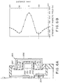
- the magnetic circuit as the magnetic field generating means comprises a magnetic substance 256 having a cylindrical shape for covering the entire peripheral surface of the upper vacuum vessel 215, a first permanent magnet 257 having a ring shape and fixed on an inner wall of the upper end of the magnetic substance 256, and a second permanent magnet 258 having a ring shape and fixed on an inner wall of the lower end of the magnetic substance 256.
- the electron gun 200B according to the third embodiment differs to other electric gun according to other embodiments at the several points as follows:
- An insulator 206 is configured in the longer size in comparison with the electron gun 200 according to the first embodiment;
- the magnetic field generating means 255 has a large scale configuration;
- the ion pump 250 is provided. Since other basic configuration are the same as the electron gun 200 according to the first embodiment, the duplicated description will be omitted.
- a magnetic source comprises two pieces of the permanent magnets 257 and 258 each having the ring shape and an axial symmetry.
- the permanent magnets 257 and 258 are arranged in parallel with the central axis direction of the electron gun 200B, and both of the magnets 257 and 258 are magnetized in the same direction along the axial direction.
- a magnetic path is formed by the magnetic substance 256 between both magnets.
- FIG. 6B is a graph showing a magnetic field distribution on the central axis of the magnetic circuit 255 comprising two magnets 257 and 258 and the magnetic substance 256.
- the maximum peak position of the magnetic field strength coincides with the position corresponding to the intermediate portion of two magnets 257 and 258, which is shown by "0" of distance graduations along the vertical axis.
- the figure shows the distribution in that the field strength decreases with receding in the distance from this position, a line of magnetic force inverts its direction, and the peaks appear again at the end of the ring shape magnets. Accordingly, one of the peaks of the magnetic distribution coincides with the portion where the aberration of the electrostatic lens system occurs, for example, the intermediate point between the leader electrode 203 and the lens electrode 204 shown in FIG. 6A.
- the gun is configured in the manner that one of the peak points coincides with the point between the leader electrode 203 and the lens electrode 204 where the aberration of the electrostatic lens system occurs. Namely, the gun is configured in the manner that the intermediate point between both electrodes 203 and 204 coincides with anyone of two peak values (-150 Gs) near ⁇ 50 mm distant from 0 in FIG. 6B.
- the electron gun according to the third embodiment is configured in the manner that one of the peak values of the magnetic field coincides with between the leader electrode 203 and lens electrode 204 where the aberration of the electrostatic lens system occurs. Namely, in FIGS 6A and 6B, the intermediate point of both the electrodes 203 and 204 coincides with anyone of the maximum peak point (300 Gs) and two other peaks (-150 Gs) which are respectively positioned near ⁇ 50 mm distant from the maximum peak.
- FIG. 7 is a graph showing changes of the spherical aberration coefficient C SO and the chromatic aberration coefficient C CO when the relative position of the electrostatic lens system and the magnetic circuit 255 changes.
- the axis of abscissa of this graph shows a distance from the intermediate position between the permanent magnets 257 and 258 to the cathode, and the axis shows the calculation results of the spherical aberration coefficient C SO and the chromatic aberration coefficient C CO on the objective side when a crossover position is fixed to a position 40 [mm] distant from the cathode.
- the minimum position of each aberration does not reside in the place where the peak position (the intermediate position of two pieces of the magnets) of the magnetic field corresponds to the cathode position, and resides in the place where the peak position corresponds to the intermediate portion between the leader electrode and the lens electrode of the electrostatic lens system.
- the aberration of the electrostatic lens system mainly occurs between the leader electrode and the lens electrode and coincides with peak position of the maximum value of the magnetic field where the aberration coefficient becomes lowest value under the condition that the crossover position is 40 [mm] distant from the cathode, an acceleration voltage is 1.0 [kV], and a voltage of the leader electrode 4.0 [kV].
- the peak of the magnetic distribution along the central axis corresponds to the intermediate position between two pieces of the ring-shaped permanent magnet. Since the outer surface of the magnetic circuit is enclosed by the magnetic substance at this position, the field distribution in the radial direction inclines toward the central axis, thereby resulting an improvement of the magnetic strength of the distribution on the axis. Therefore, the electron gun of the third embodiment can be obtain higher magnetic distribution on the axis in comparison with the magnetic circuit comprising the a piece of the ring shape magnet and magnetic substance according to the first embodiment of the present invention shown in FIG. 2.
- the electron gun 200C according to the fourth embodiment has substantially the same configuration of the electron gun 200B according to the third embodiment, and has two different points that one is a provision of the automatic position detection control mechanism 223 having the same configuration as the electron gun 200A according to the second embodiment, and another is a displacement from the permanent magnet 258 to an electromagnet 259 in the magnetic circuit 255 as the magnetic field generating means.
- the automatic position detection control mechanism 223 as the first different point controls a drive of the moving mechanism 221 for regulating the movement of the magnetic substance 256 of the magnetic circuit 255 in the Z-direction on the basis of respective set value of the power sources 212, 213 and 214, and has the same configuration and operation as the electron gun according to the second embodiment.
- the permanent magnet 258 is displaced by the electromagnet 259 in the fourth embodiment to interpose the composite magnetic field of the permanent magnet 257 and the electromagnet 259 to the electrostatic lens system, it is possible to obtain the same effect as the third embodiment.
- the high magnetic field can superpose to the electrostatic lens system.
- the magnetic field strength of the electromagnet is changed by the variable current source 222, the field distribution can change to superpose over the electrostatic lens system, and the electron gun has an advantage that it is possible to simply set the maximum value of the field distribution to an arbitrary portion where the aberration occurs.
- the electron gun 200D of the fifth embodiment has two points different from the first through the fourth embodiments.
- a first different point resides in that the magnetic circuit 300 as the magnetic field generating means is different from the former embodiments.
- a second different point resides in that the intermediate portion between the leader electrode 203 and the lens electrode 204 coincides with the substantial intermediate point in the longitudinal direction of the magnetic substance 303 constructing the magnetic circuit 300.
- an outline of the magnetic field generating means is longitudinal cylindrical tank shape as the same as the third and fourth embodiments, since the ion pump 250 is not provided, it is possible to provide the electrostatic lens system at the portion corresponding to the maximum peak of the magnet field strength.
- the central portion of the lower vacuum vessel 217 upwardly rises on the figure in the manner being as a pedestal of the electrostatic lens system.
- An insulator 207 is set on the pedestal, and the leader electrode 203, lens electrode 204 and anode 205 are attached with the insulator 207 in the same manner as the electron gun according to the first through the fourth embodiments.
- the magnetic circuit 300 comprises an electromagnet 301 of the upper end, an electromagnet 302 of the lower end, and a magnetic substance 303 to which the electromagnets 301 and 302 are mounted on the inner walls of the upper end and lower end thereof, respectively.
- the electromagnet 302 is connected to the variable current source 222 as the same manner as the fourth embodiment, and the electromagnet 301 is also connected to a variable current source 333.
- the electron gun 200E of the sixth embodiment is the best mode of the present invention.
- the electron gun 200E according to the sixth embodiment basically has the same configuration as the electron gun 200D according to the fifth embodiment.
- the different point from the fifth embodiment resides in that the gun 200E has an automatic position detection control mechanism 223 for automatically controlling the moving mechanism 221 which causes the magnetic substance 303 of the magnetic circuit 300 as the magnetic field generating means to be moved in the Z-direction to the desired position.
- the automatic position detection control mechanism 223 outputs a drive control command to the moving mechanism 221 on the basis of the respective set value of the power sources 212, 213 and 214 in the same manner as that of the second through fourth embodiments.
- the moving mechanism 221 causes the magnetic circuit 300 by rotating such as the motor with the predetermined amount on the basis of the drive control command. By this, it is possible to automatically coincide the most conspicuous portion of the aberration of the electrostatic lens system with the peak point of the magnetic field strength.
- variable current sources 222 and 333 are controlled by a control signal supplied from the automatic position detection control mechanism 223.
Landscapes
- Chemical & Material Sciences (AREA)
- Analytical Chemistry (AREA)
- Electron Sources, Ion Sources (AREA)
- Electron Beam Exposure (AREA)
Applications Claiming Priority (2)
| Application Number | Priority Date | Filing Date | Title |
|---|---|---|---|
| JP228685/92 | 1992-08-27 | ||
| JP22868592 | 1992-08-27 |
Publications (2)
| Publication Number | Publication Date |
|---|---|
| EP0585840A1 true EP0585840A1 (fr) | 1994-03-09 |
| EP0585840B1 EP0585840B1 (fr) | 1996-10-16 |
Family
ID=16880206
Family Applications (1)
| Application Number | Title | Priority Date | Filing Date |
|---|---|---|---|
| EP93113752A Expired - Lifetime EP0585840B1 (fr) | 1992-08-27 | 1993-08-27 | Canon à électrons à effet de champ muni d'une lentille à immersion permettant de réduire l'aberration d'une lentille électrostatique |
Country Status (4)
| Country | Link |
|---|---|
| US (1) | US5371371A (fr) |
| EP (1) | EP0585840B1 (fr) |
| KR (1) | KR970005769B1 (fr) |
| DE (1) | DE69305463T2 (fr) |
Cited By (4)
| Publication number | Priority date | Publication date | Assignee | Title |
|---|---|---|---|---|
| NL1002246C2 (nl) * | 1995-02-06 | 1998-07-13 | Nat Res Inst Metals | Door een laser bestraald electronenkanon. |
| WO2000052733A1 (fr) * | 1999-03-05 | 2000-09-08 | Etec Systems, Inc. | Canon d'electrons a effet schottky et a emission de champs avec intensite angulaire accrue |
| EP1471562A3 (fr) * | 2003-04-24 | 2006-11-22 | FEI Company | Appareil optique à particules avec une lentille à aimant permanent et une lentille électrostatique |
| EP3443822A4 (fr) * | 2016-04-11 | 2019-10-23 | Kla-Tencor Corporation | Appareil à faisceau de particules à aimant permanent et procédé comprenant une partie métallique non magnétique pour une accordabilité |
Families Citing this family (34)
| Publication number | Priority date | Publication date | Assignee | Title |
|---|---|---|---|---|
| WO1998025293A2 (fr) * | 1996-12-03 | 1998-06-11 | Koninklijke Philips Electronics N.V. | Procede d'exploitation d'un appareil optique a particules |
| DE69605053T2 (de) * | 1996-12-24 | 2000-02-24 | Advantest Corp., Saitama | Kanonenlinse zur Partikelstrahlerzeugung |
| US6069363A (en) * | 1998-02-26 | 2000-05-30 | International Business Machines Corporation | Magnetic-electrostatic symmetric doublet projection lens |
| EP0943242A1 (fr) * | 1998-02-26 | 1999-09-22 | Puratos N.V. | Compositions granulées d'amélioration du pain et leur utilisation pour la fabrication de produits de boulangerie |
| SG102573A1 (en) * | 2000-05-04 | 2004-03-26 | Univ Singapore | A lens for a scanning electron microscope |
| US7135821B2 (en) * | 2003-10-01 | 2006-11-14 | Altera Corporation | High-definition cathode ray tube and electron gun |
| US7893406B1 (en) * | 2005-06-29 | 2011-02-22 | Hermes-Microvision, Inc. | Electron gun with magnetic immersion double condenser lenses |
| DE102007010873B4 (de) * | 2007-03-06 | 2009-07-30 | Carl Zeiss Nts Gmbh | Objektivlinse |
| JP2010055756A (ja) * | 2008-08-26 | 2010-03-11 | Hitachi High-Technologies Corp | 荷電粒子線の照射方法及び荷電粒子線装置 |
| KR100964094B1 (ko) * | 2008-11-10 | 2010-06-16 | 포항공과대학교 산학협력단 | 펨토초 전자 빔 발생 장치 및 방법 |
| JP5386229B2 (ja) * | 2009-05-22 | 2014-01-15 | 株式会社日立ハイテクノロジーズ | 電子銃 |
| JP5504277B2 (ja) * | 2009-11-26 | 2014-05-28 | 株式会社日立ハイテクノロジーズ | 走査電子顕微鏡 |
| US8461526B2 (en) | 2010-12-01 | 2013-06-11 | Kla-Tencor Corporation | Electron beam column and methods of using same |
| KR20140128975A (ko) * | 2011-12-29 | 2014-11-06 | 엘화 엘엘씨 | 그래핀 그리드를 갖는 전자적 디바이스 |
| US8928228B2 (en) | 2011-12-29 | 2015-01-06 | Elwha Llc | Embodiments of a field emission device |
| US8575842B2 (en) | 2011-12-29 | 2013-11-05 | Elwha Llc | Field emission device |
| US9349562B2 (en) | 2011-12-29 | 2016-05-24 | Elwha Llc | Field emission device with AC output |
| US9646798B2 (en) | 2011-12-29 | 2017-05-09 | Elwha Llc | Electronic device graphene grid |
| US8946992B2 (en) | 2011-12-29 | 2015-02-03 | Elwha Llc | Anode with suppressor grid |
| US8810161B2 (en) | 2011-12-29 | 2014-08-19 | Elwha Llc | Addressable array of field emission devices |
| US8810131B2 (en) | 2011-12-29 | 2014-08-19 | Elwha Llc | Field emission device with AC output |
| US9171690B2 (en) * | 2011-12-29 | 2015-10-27 | Elwha Llc | Variable field emission device |
| US9018861B2 (en) | 2011-12-29 | 2015-04-28 | Elwha Llc | Performance optimization of a field emission device |
| US8692226B2 (en) | 2011-12-29 | 2014-04-08 | Elwha Llc | Materials and configurations of a field emission device |
| US8970113B2 (en) | 2011-12-29 | 2015-03-03 | Elwha Llc | Time-varying field emission device |
| US9627168B2 (en) | 2011-12-30 | 2017-04-18 | Elwha Llc | Field emission device with nanotube or nanowire grid |
| US9659734B2 (en) | 2012-09-12 | 2017-05-23 | Elwha Llc | Electronic device multi-layer graphene grid |
| US9659735B2 (en) | 2012-09-12 | 2017-05-23 | Elwha Llc | Applications of graphene grids in vacuum electronics |
| KR101456794B1 (ko) * | 2013-08-08 | 2014-11-03 | (주)오로스 테크놀로지 | 빔 스폿 조절이 가능한 주사전자현미경 및 이를 이용한 측정방법 |
| JP6027150B2 (ja) * | 2014-06-24 | 2016-11-16 | 内海 孝雄 | 低エネルギー電子ビームリソグラフィ |
| JP6324241B2 (ja) * | 2014-07-07 | 2018-05-16 | 株式会社日立ハイテクノロジーズ | 荷電粒子線装置および収差補正器 |
| US9799484B2 (en) * | 2014-12-09 | 2017-10-24 | Hermes Microvision, Inc. | Charged particle source |
| US10410827B2 (en) | 2017-05-03 | 2019-09-10 | Fei Company | Gun lens design in a charged particle microscope |
| WO2019133433A1 (fr) | 2017-12-28 | 2019-07-04 | Fei Company | Procédé, dispositif et système permettant de réduire une aberration non axiale en microscopie électronique |
Citations (2)
| Publication number | Priority date | Publication date | Assignee | Title |
|---|---|---|---|---|
| JPH02204946A (ja) * | 1989-02-01 | 1990-08-14 | Mitsubishi Electric Corp | ビデオプロジェクタ用陰極線管 |
| EP0462554A2 (fr) * | 1990-06-20 | 1991-12-27 | Hitachi, Ltd. | Appareil à faisceau de particules chargées |
Family Cites Families (7)
| Publication number | Priority date | Publication date | Assignee | Title |
|---|---|---|---|---|
| US2714678A (en) * | 1950-09-03 | 1955-08-02 | Siemens Ag | Electron microscopes |
| US3818394A (en) * | 1966-06-10 | 1974-06-18 | Hitachi Ltd | Electron lens for electron microscope and the like |
| US4675524A (en) * | 1985-03-11 | 1987-06-23 | Siemens Aktiengesellschaft | Scanning particle microscope with diminished boersch effect |
| US4926054A (en) * | 1988-03-17 | 1990-05-15 | Ict Integrated Circuit Testing Gesellschaft Fur Halbleiterpruftechnik Mbh | Objective lens for focusing charged particles in an electron microscope |
| JPH0237651A (ja) * | 1988-07-27 | 1990-02-07 | Mitsubishi Electric Corp | 電子銃 |
| US5079428A (en) * | 1989-08-31 | 1992-01-07 | Bell Communications Research, Inc. | Electron microscope with an asymmetrical immersion lens |
| US5146090A (en) * | 1990-06-11 | 1992-09-08 | Siemens Aktiengesellschaft | Particle beam apparatus having an immersion lens arranged in an intermediate image of the beam |
-
1993
- 1993-08-26 KR KR1019930016658A patent/KR970005769B1/ko not_active Expired - Fee Related
- 1993-08-27 EP EP93113752A patent/EP0585840B1/fr not_active Expired - Lifetime
- 1993-08-27 DE DE69305463T patent/DE69305463T2/de not_active Expired - Fee Related
- 1993-08-27 US US08/112,802 patent/US5371371A/en not_active Expired - Lifetime
Patent Citations (2)
| Publication number | Priority date | Publication date | Assignee | Title |
|---|---|---|---|---|
| JPH02204946A (ja) * | 1989-02-01 | 1990-08-14 | Mitsubishi Electric Corp | ビデオプロジェクタ用陰極線管 |
| EP0462554A2 (fr) * | 1990-06-20 | 1991-12-27 | Hitachi, Ltd. | Appareil à faisceau de particules chargées |
Non-Patent Citations (4)
| Title |
|---|
| DELONG ET AL.: "A new design of field emission electron gun with a magnetic lens", OPTIK, vol. 81, 1989, STUTTGART DE, pages 103 - 108, XP000048491 * |
| KATSUTA ET AL.: "The characteristics of a magnetic-field-immersed pulse field emission gun", PROC. XITH INT. CONG. ON ELECTRON MICROSCOPY, 1986, KYOTO, pages 267 - 268, XP000010057 * |
| PATENT ABSTRACTS OF JAPAN vol. 14, no. 493 (E - 995) 26 October 1990 (1990-10-26) * |
| YAMAZAKI ET AL.: "Development of the field emission electron gun integrated in the sputter ion pump", JOURNAL OF VACUUM SCIENCE AND TECHNOLOGY: PART B, vol. 9, November 1991 (1991-11-01), NEW YORK US, pages 2967 - 2971, XP000268508, DOI: doi:10.1116/1.585635 * |
Cited By (4)
| Publication number | Priority date | Publication date | Assignee | Title |
|---|---|---|---|---|
| NL1002246C2 (nl) * | 1995-02-06 | 1998-07-13 | Nat Res Inst Metals | Door een laser bestraald electronenkanon. |
| WO2000052733A1 (fr) * | 1999-03-05 | 2000-09-08 | Etec Systems, Inc. | Canon d'electrons a effet schottky et a emission de champs avec intensite angulaire accrue |
| EP1471562A3 (fr) * | 2003-04-24 | 2006-11-22 | FEI Company | Appareil optique à particules avec une lentille à aimant permanent et une lentille électrostatique |
| EP3443822A4 (fr) * | 2016-04-11 | 2019-10-23 | Kla-Tencor Corporation | Appareil à faisceau de particules à aimant permanent et procédé comprenant une partie métallique non magnétique pour une accordabilité |
Also Published As
| Publication number | Publication date |
|---|---|
| DE69305463T2 (de) | 1997-03-20 |
| DE69305463D1 (de) | 1996-11-21 |
| KR940004661A (ko) | 1994-03-15 |
| KR970005769B1 (ko) | 1997-04-19 |
| EP0585840B1 (fr) | 1996-10-16 |
| US5371371A (en) | 1994-12-06 |
Similar Documents
| Publication | Publication Date | Title |
|---|---|---|
| EP0585840B1 (fr) | Canon à électrons à effet de champ muni d'une lentille à immersion permettant de réduire l'aberration d'une lentille électrostatique | |
| US7872240B2 (en) | Corrector for charged-particle beam aberration and charged-particle beam apparatus | |
| US4100055A (en) | Target profile for sputtering apparatus | |
| JP2732961B2 (ja) | 荷電粒子線装置 | |
| US8362443B2 (en) | Objective lens | |
| JPH0799027A (ja) | 電子ビーム集束装置 | |
| US9343260B2 (en) | Multipole and charged particle radiation apparatus using the same | |
| KR100282600B1 (ko) | 원뿔형 극편이 구비되어 있는 복합 동심-갭 자기렌즈 및 디플렉터 | |
| US5677530A (en) | Scanning electron microscope | |
| EP0133016A2 (fr) | Lentille magnétique à intervalles multiples par la focalisation des faisceaux de particules chargées | |
| US20230065039A1 (en) | Particle beam column | |
| EP0084653A2 (fr) | Lentille magnétique composite à entrefers concentriques | |
| US5021670A (en) | Multipole element | |
| US4945247A (en) | Field emission electron gun system | |
| US6653632B2 (en) | Scanning-type instrument utilizing charged-particle beam and method of controlling same | |
| JP2835265B2 (ja) | 磁界界浸型電子銃及び磁界界浸型電子銃操作方法 | |
| JP2002134051A (ja) | 電磁界重畳型レンズ及びこれを用いた電子線装置 | |
| JP2000090866A (ja) | 電子銃、電子銃による電子ビーム発生方法及び電子銃を用いた露光装置 | |
| JP2000003689A (ja) | 電子銃とそれを用いた露光装置 | |
| US4201933A (en) | Electron gun structure for a pickup tube | |
| TWI917910B (zh) | 帶電粒子線裝置 | |
| GB1367360A (en) | Electron-optical apparatus | |
| KR102921229B1 (ko) | 하전 입자 빔 제어 디바이스, 및 그것을 구비하는 하전 입자 빔 장치 | |
| US11201033B2 (en) | Charged particle beam device and electrostatic lens | |
| JPH10208653A (ja) | イオン源装置及びこれを用いた集束イオンビーム装置 |
Legal Events
| Date | Code | Title | Description |
|---|---|---|---|
| PUAI | Public reference made under article 153(3) epc to a published international application that has entered the european phase |
Free format text: ORIGINAL CODE: 0009012 |
|
| 17P | Request for examination filed |
Effective date: 19930827 |
|
| AK | Designated contracting states |
Kind code of ref document: A1 Designated state(s): DE FR GB |
|
| 17Q | First examination report despatched |
Effective date: 19950310 |
|
| GRAH | Despatch of communication of intention to grant a patent |
Free format text: ORIGINAL CODE: EPIDOS IGRA |
|
| GRAH | Despatch of communication of intention to grant a patent |
Free format text: ORIGINAL CODE: EPIDOS IGRA |
|
| GRAA | (expected) grant |
Free format text: ORIGINAL CODE: 0009210 |
|
| AK | Designated contracting states |
Kind code of ref document: B1 Designated state(s): DE FR GB |
|
| REF | Corresponds to: |
Ref document number: 69305463 Country of ref document: DE Date of ref document: 19961121 |
|
| ET | Fr: translation filed | ||
| PLBE | No opposition filed within time limit |
Free format text: ORIGINAL CODE: 0009261 |
|
| 26N | No opposition filed | ||
| REG | Reference to a national code |
Ref country code: GB Ref legal event code: IF02 |
|
| PGFP | Annual fee paid to national office [announced via postgrant information from national office to epo] |
Ref country code: DE Payment date: 20080912 Year of fee payment: 16 |
|
| PGFP | Annual fee paid to national office [announced via postgrant information from national office to epo] |
Ref country code: FR Payment date: 20080818 Year of fee payment: 16 |
|
| PGFP | Annual fee paid to national office [announced via postgrant information from national office to epo] |
Ref country code: GB Payment date: 20080903 Year of fee payment: 16 |
|
| GBPC | Gb: european patent ceased through non-payment of renewal fee |
Effective date: 20090827 |
|
| REG | Reference to a national code |
Ref country code: FR Ref legal event code: ST Effective date: 20100430 |
|
| PG25 | Lapsed in a contracting state [announced via postgrant information from national office to epo] |
Ref country code: FR Free format text: LAPSE BECAUSE OF NON-PAYMENT OF DUE FEES Effective date: 20090831 Ref country code: DE Free format text: LAPSE BECAUSE OF NON-PAYMENT OF DUE FEES Effective date: 20100302 |
|
| PG25 | Lapsed in a contracting state [announced via postgrant information from national office to epo] |
Ref country code: GB Free format text: LAPSE BECAUSE OF NON-PAYMENT OF DUE FEES Effective date: 20090827 |