EP0585844A1 - Halteklammer zur axial verschiebbaren Befestigung von Stäben - Google Patents
Halteklammer zur axial verschiebbaren Befestigung von Stäben Download PDFInfo
- Publication number
- EP0585844A1 EP0585844A1 EP93113779A EP93113779A EP0585844A1 EP 0585844 A1 EP0585844 A1 EP 0585844A1 EP 93113779 A EP93113779 A EP 93113779A EP 93113779 A EP93113779 A EP 93113779A EP 0585844 A1 EP0585844 A1 EP 0585844A1
- Authority
- EP
- European Patent Office
- Prior art keywords
- thread
- threaded rod
- retaining
- holding
- plate
- Prior art date
- Legal status (The legal status is an assumption and is not a legal conclusion. Google has not performed a legal analysis and makes no representation as to the accuracy of the status listed.)
- Granted
Links
Images

Classifications
-
- E—FIXED CONSTRUCTIONS
- E04—BUILDING
- E04B—GENERAL BUILDING CONSTRUCTIONS; WALLS, e.g. PARTITIONS; ROOFS; FLOORS; CEILINGS; INSULATION OR OTHER PROTECTION OF BUILDINGS
- E04B9/00—Ceilings; Construction of ceilings, e.g. false ceilings; Ceiling construction with regard to insulation
- E04B9/18—Means for suspending the supporting construction
- E04B9/20—Means for suspending the supporting construction adjustable
- E04B9/205—Means for suspending the supporting construction adjustable by means of a resilient clip
-
- F—MECHANICAL ENGINEERING; LIGHTING; HEATING; WEAPONS; BLASTING
- F16—ENGINEERING ELEMENTS AND UNITS; GENERAL MEASURES FOR PRODUCING AND MAINTAINING EFFECTIVE FUNCTIONING OF MACHINES OR INSTALLATIONS; THERMAL INSULATION IN GENERAL
- F16B—DEVICES FOR FASTENING OR SECURING CONSTRUCTIONAL ELEMENTS OR MACHINE PARTS TOGETHER, e.g. NAILS, BOLTS, CIRCLIPS, CLAMPS, CLIPS OR WEDGES; JOINTS OR JOINTING
- F16B2/00—Friction-grip releasable fastenings
- F16B2/20—Clips, i.e. with gripping action effected solely by the inherent resistance to deformation of the material of the fastening
- F16B2/22—Clips, i.e. with gripping action effected solely by the inherent resistance to deformation of the material of the fastening of resilient material, e.g. rubbery material
- F16B2/24—Clips, i.e. with gripping action effected solely by the inherent resistance to deformation of the material of the fastening of resilient material, e.g. rubbery material of metal
- F16B2/241—Clips, i.e. with gripping action effected solely by the inherent resistance to deformation of the material of the fastening of resilient material, e.g. rubbery material of metal of sheet metal
- F16B2/245—Clips, i.e. with gripping action effected solely by the inherent resistance to deformation of the material of the fastening of resilient material, e.g. rubbery material of metal of sheet metal external, i.e. with contracting action
- F16B2/246—Clips, i.e. with gripping action effected solely by the inherent resistance to deformation of the material of the fastening of resilient material, e.g. rubbery material of metal of sheet metal external, i.e. with contracting action the clip being released by tilting the clip or a part thereof to a position in which the axis of the openings surrounding the gripped elements is parallel to, or coincides with, the axis of the gripped elements
-
- F—MECHANICAL ENGINEERING; LIGHTING; HEATING; WEAPONS; BLASTING
- F16—ENGINEERING ELEMENTS AND UNITS; GENERAL MEASURES FOR PRODUCING AND MAINTAINING EFFECTIVE FUNCTIONING OF MACHINES OR INSTALLATIONS; THERMAL INSULATION IN GENERAL
- F16L—PIPES; JOINTS OR FITTINGS FOR PIPES; SUPPORTS FOR PIPES, CABLES OR PROTECTIVE TUBING; MEANS FOR THERMAL INSULATION IN GENERAL
- F16L3/00—Supports for pipes, cables or protective tubing, e.g. hangers, holders, clamps, cleats, clips, brackets
- F16L3/08—Supports for pipes, cables or protective tubing, e.g. hangers, holders, clamps, cleats, clips, brackets substantially surrounding the pipe, cable or protective tubing
- F16L3/10—Supports for pipes, cables or protective tubing, e.g. hangers, holders, clamps, cleats, clips, brackets substantially surrounding the pipe, cable or protective tubing divided, i.e. with two members engaging the pipe, cable or protective tubing
- F16L3/11—Supports for pipes, cables or protective tubing, e.g. hangers, holders, clamps, cleats, clips, brackets substantially surrounding the pipe, cable or protective tubing divided, i.e. with two members engaging the pipe, cable or protective tubing and hanging from a pendant
-
- F—MECHANICAL ENGINEERING; LIGHTING; HEATING; WEAPONS; BLASTING
- F16—ENGINEERING ELEMENTS AND UNITS; GENERAL MEASURES FOR PRODUCING AND MAINTAINING EFFECTIVE FUNCTIONING OF MACHINES OR INSTALLATIONS; THERMAL INSULATION IN GENERAL
- F16B—DEVICES FOR FASTENING OR SECURING CONSTRUCTIONAL ELEMENTS OR MACHINE PARTS TOGETHER, e.g. NAILS, BOLTS, CIRCLIPS, CLAMPS, CLIPS OR WEDGES; JOINTS OR JOINTING
- F16B37/00—Nuts or like thread-engaging members
- F16B37/08—Quickly-detachable or mountable nuts, e.g. consisting of two or more parts; Nuts movable along the bolt after tilting the nut
Definitions
- the invention relates to a retaining clip for the axially displaceable fastening of rods according to the preamble of claim 1.
- Retaining clips of this type are known in practice and are used, for example, for hanging ceilings, cable ducts or other elongate components. They offer the advantage that the holding clamp or the holding rod can be easily moved in the clamp by compressing the holding legs, which is important when aligning ceilings or channels horizontally. In contrast, the holding force of this clamp is not particularly high and is therefore often not suitable for heavy ceiling loads.
- the object of the invention is therefore to design the retaining clip so that much heavier loads can be held.
- a half-open thread carrier is fastened to the holding plate between the holding legs, the thread of which engages in the relaxed state of the holding leg in the thread of the threaded rod.
- the holding clip designed in this way not only has a considerably greater holding force than the conventional clip, as desired, but also offers also makes it easier to precisely align the individual breakpoints. After the holding rods have been roughly brought to the desired height by pressing the holding legs together, the exact height can now be reached quickly and easily by turning the threaded rod in the bracket. This significantly reduces the assembly time for hanging the ceiling.
- the existing board material can be used even better if at least two support tabs are provided on the holding plate between the axially parallel thread edges, which are punched out of the holding plate and are pressed in to the hole axis to the extent that these support tabs with the thread teeth simultaneously in engage the thread grooves of the threaded rod.
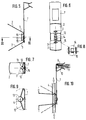
- the holding clip shown in the figures consists essentially of a holding plate 1 and two holding legs 2 which spring apart from this plate 1 in a V-shape and are made of spring steel.
- the holding legs 2 are at the same distance from the holding plate 1, two holes 3 aligned with one another for receiving and fixing a threaded rod 4.
- the holes 3 are dimensioned in such a way that the threaded rod 4 can easily be inserted into the holes 3 when the holding legs 2 are compressed. As soon as the rod 4 to the holding plate 1 has reached the desired position, the two holding legs 2 are allowed to spring back into their starting position, so that the rod 4 is pressed towards the holding plate 1 by the edge edges 5 of the two holes 3 resting on the rod 4.
- a half-open threaded stone 6 is fastened, the thread of which engages in the relaxed, diverging state of the holding leg 2 in the thread of the threaded rod 4, so that the holding force between the clamp and the rod is increased many times over.
- the holding plate 1 is connected to a component 7 on the side facing away from the threaded stone 6, the connection being expediently made by a pin 8 protruding from the threaded stone 6 and passing through holes in the plate 1 and the component 7.
- the component 7 has at its upper end two resiliently bendable clamping legs 9 and 10 for attachment to a carrier 11.
- FIGS. 3 and 4 The function of the retaining clip can be seen from FIGS. 3 and 4.
- the carrier 11 which may consist, for example, of ceiling beams or profiled strips
- the two holding legs 2 are pressed together by hand, so that the holes 3 are moved somewhat away from the threaded stone 6.
- the way is now clear for inserting the threaded rod 4 (FIG. 3).
- the holding legs 2 are allowed to spring apart again.
- the threaded rod 4 is pressed into the threaded block 4 so that the two threads engage (FIG. 4).
- the threaded rod 4 can be rotated in the direction of arrow "D", so that fine adjustment to the exact altitude is now possible. This is necessary, for example, when hanging ceilings in order to be able to set the suspension points for the ceiling (not shown in the drawing) to exactly the same height.
- tines 14 adapted to the threaded grooves of the threaded rod 4 are cut, which in the relaxed, ie diverging position of the holding legs 2 into the thread of the Engage rod 4.
- At least two support tabs 1.5 directed obliquely onto the threaded rod 4 are provided on the holding plate 1 between the axially parallel thread edges 13. These can be produced in a simple manner by punching them out of the holding plate 1 and then pressing them to the hole axis to such an extent that the support tabs 15 with the thread teeth 14 simultaneously engage in the grooves of the threaded rod 4 and are supported on the thread flanks.
- This embodiment allows an inexpensive manufacture of the retaining clip from only one sheet metal strip, the so-called circuit board, so that the manufacturing costs for the individual fastening points are significantly lower compared to the embodiment according to FIGS. 1-4, because in the former embodiment with the threaded block 6 an additional plastic part is needed.
Landscapes
- Engineering & Computer Science (AREA)
- General Engineering & Computer Science (AREA)
- Architecture (AREA)
- Mechanical Engineering (AREA)
- Physics & Mathematics (AREA)
- Electromagnetism (AREA)
- Civil Engineering (AREA)
- Structural Engineering (AREA)
- Clamps And Clips (AREA)
- Reinforcement Elements For Buildings (AREA)
Abstract

Description
- Die Erfindung bezieht sich auf eine Halteklammer zur axial verschiebbaren Befestigung von Stäben gemäß dem Oberbegriff des Anspruchs 1.
- Derartige Halteklammern sind in der Praxis bekannt und werden beispielsweise verwendet zum Abhängen von Decken, Kabelkanälen oder sonstigen langgestreckten Bauteilen. Sie bieten den Vorteil, daß sich die Halteklammer beziehungsweise der Haltestab in der Klammer durch Zusammendrücken der Halteschenkel leicht verschieben lassen, was beim horizontalen Ausrichten von Decken oder Kanälen wichtig ist. Dagegen ist die Haltekraft dieser Klammer nicht besonders hoch und daher für schwere Deckenlasten oft nicht geeignet.
- Aufgabe der Erfindung ist es daher, die Halteklammer so zu gestalten, daß wesentlich stärkere Lasten gehalten werden können.
- Diese Aufgabe wird nach der Erfindung dadurch gelöst, daß an der Halteplatte zwischen den Halteschenkeln ein halbseits offener Gewindeträger befestigt ist, dessen Gewinde im entspannten Zustand der Halteschenkel in das Gewinde des Gewindestabes eingreift.
- Die so gestaltete Halteklammer besitzt gegenüber der herkömmlichen Klammer nicht nur, wie angestrebt, eine beträchtlich größere Haltekraft, sondern bietet darüberhinaus auch eine Erleichterung beim genauen Ausrichten der einzelnen Haltepunkte. Nachdem die Haltestangen durch Zusammendrücken der Halteschenkel zunächst grob auf die gewünschte Höhe gebracht worden sind, kann nun die exakte Höhenlage schnell und problemlos durch Drehen des Gewindestabes in der Klammer erreicht werden. Damit läßt sich die Montagezeit zum Abhängen der Decke deutlich reduzieren.
- Um die Halteklammer kostengünstig aus einer einzigen Metallplatine herstellen zu können, ist es in weiterer Ausgestaltung der Erfindung zweckmäßig, wenn als Gewindeträger an der Halteplatte zwei schräg abstehende, zur Lochachse hinweisende Gewindelappen angeformt sind, in deren achsparallelen Kanten dem Gewinde des Gewindestabes angepaßte Zacken eingeschnitten sind.
- Hierbei läßt sich das vorhandene Platinenmaterial noch besser nutzen, wenn an der Halteplatte zwischen den achsparallelen Gewindekanten mindestens zwei schräg auf den Gewindestab gerichtete Stützlappen vorgesehen sind, welche aus der Halteplatte ausgestanzt und soweit zur Lochachse hin eingedrückt sind, daß diese Stützlappen mit den Gewindezacken gleichzeitig in die Gewinderillen des Gewindestabes eingreifen.
- In der Zeichnung sind zwei Ausführungsbeispiele der Erfindung dargestellt, welche nachfolgend näher erläutert werden.
- Es zeigt:
- Fig. 1
- eine erfindungsgemäße Halteklammer in Seitenansicht mit Teilschnitt durch den Haltebereich des Gewindestabes,
- Fig. 2
- die Halteklammer in Vorderansicht,
- Fig. 3
- die an einem Träger befestigte Halteklammer mit zusammengedrückten Schenkeln zum Einschieben des Gewindestabes,
- Fig. 4
- die gleiche Montagesituation mit entspannten Schenkeln zum Halten des Gewindestabes,
- Fig. 5
- eine andere Ausführungsform der Halteklammer in Seitenansicht,
- Fig. 6
- die gleiche Halteklammer in Vorderansicht,
- Fig. 7
- einen Schnitt durch den Haltebereich gemäß Linie VII - VII in Figur 5,
- Fig. 8
- eine Vergrößerung der Gewindezacken gemäß Figur 6,
- Fig. 9
- eine Vergrößerung des Haltebereichs gemäß Figur 7 und
- Fig. 10
- die Halteklammer in montiertem Zustand wie Figur 3.
- Die in den Figuren dargestellte Halteklammer besteht im wesentlichen aus einer Halteplatte 1 und zwei von dieser Platte 1 V-förmig auseinanderstrebenden Halteschenkeln 2 aus Federbandstahl. In den Halteschenkeln 2 befinden sich im gleichen Abstand von der Halteplatte 1 zwei zueinander fluchtende Löcher 3 zur Aufnahme und Fixierung eines Gewindestabes 4.
- Die Löcher 3 sind in ihrem Durchmesser so bemessen, daß sich der Gewindestab 4 bei zusammengedrückten Halteschenkeln 2 leicht in die Löcher 3 einführen läßt. Sobald der Stab 4 zu der Halteplatte 1 die gewünschte Lage erreicht hat, läßt man die beiden Halteschenkel 2 in ihre Ausgangslage zurückfedern, so daß der Stab 4 durch die sich am Stab 4 anlegenden Randkanten 5 der beiden Löcher 3 zur Halteplatte 1 hin gedrückt wird.
- An der Halteplatte 1 ist ein halbseits offener Gewindestein 6 befestigt, dessen Gewinde im entspannten, auseinanderstrebenden Zustand der Halteschenkel 2 in das Gewinde des Gewindestabes 4 eingreift, so daß die Haltekraft zwischen Klammer und Stab um ein Vielfaches erhöht wird.
- Die Halteplatte 1 ist auf der vom Gewindestein 6 abgekehrten Seite mit einem Bauteil 7 verbunden, wobei die Verbindung zweckmäßigerweise durch einen vom Gewindestein 6 abstehenden und durch Löcher in der Platte 1 und dem Bauteil 7 hindurchgeführten Zapfen 8 hergestellt wird. Das Bauteil 7 besitzt an seinem oberen Ende zwei federnd auseinanderbiegbare Klemmschenkel 9 und 10 zur Befestigung an einem Träger 11.
- Die Funktion der Halteklammer ist aus den Figuren 3 und 4 ersichtlich. Nach der Befestigung des Bauteils 7 an den Träger 11, welcher beispielsweise aus Deckenbalken oder Profilleisten bestehen kann, werden die beiden Halteschenkel 2 von Hand zusammengedrückt, so daß die Löcher 3 etwas vom Gewindestein 6 wegbewegt werden. Nun ist der Weg frei zum Einführen des Gewindestabes 4 (Figur 3). Nachdem dieser grob auf die gewünschte Lage bzw. Höhe gebracht worden ist, läßt man die Halteschenkel 2 wieder auseinanderfedern. Hierbei wird der Gewindestab 4 in den Gewindestein 4 eingedrückt, so daß die beiden Gewinde ineinandergreifen (Figur 4).
- In dieser Lage kann der Gewindestab 4 in Richtung des Pfeiles "D" gedreht werden, so daß nunmehr eine Feineinstellung auf die exakte Höhenlage möglich ist. Dies ist beispielsweise beim Abhängen von Decken erforderlich, um die in der Zeichnung nicht dargestellten Aufhängepunkte für die Decke genau auf die gleiche Höhe einstellen zu können.
- Bei der in den Figuren 5 bis 10 dargestellten Ausführungsform der Halteklammer sind an der Halteplatte 1 anstelle des Gewindesteins 6 zwei schräg abstehende, zum Gewindestab 4 bzw. zur Lochachse weisende Gewindelappen 12 angeformt, welche beim Fertigen der Halteklammer zunächst an der Halteplatte 1 zwischen den beiden Schenkeln 2 in der Platine quer abstehend ausgestanzt und dann zur Halteplatte 1 nach innen soweit umgebogen werden, bis die Plattenebene auf die Achse der Löcher 3 gerichtet ist. Wie aus Figur 6 und im Detail aus Figur 8 ersichtlich, sind in den zum Gewindestab 4 hingebogenen achsparallelen Kanten 13 der Gewindelappen 12 den Gewinderillen des Gewindestabs 4 angepaßte Zacken 14 eingeschnitten, welche in der entspannten, d.h. auseinanderstrebenden Lage der Halteschenkel 2 in das Gewinde des Stabes 4 eingreifen.
- Zur weiteren Abstützung des Gewindestabes 4 an der Klammer sind an der Halteplatte 1 zwischen den achsparallelen Gewindekanten 13 mindestens zwei, schräg auf den Gewindestab 4 gerichtete Stützlappen 1,5 vorgesehen. Diese lassen sich auf einfache Weise dadurch erzeugen, daß sie aus der Halteplatte 1 ausgestanzt und dann soweit zur Lochachse gedrückt werden, daß die Stützlappen 15 mit den Gewindezacken 14 gleichzeitig in die Rillen des Gewindestabes 4 eingreifen und sich auf den Gewindeflanken abstützen.
- Diese Ausführungsform gestattet eine kostengünstige Herstellung der Halteklammer aus nur einem Blechstreifen, der sogenannten Platine, so daß die Herstellungskosten für die einzelnen Befestigungsstellen gegenüber der Ausführungsform nach Figur 1 - 4 deutlich niedriger liegen, weil bei der erstgenannten Ausführungsform mit dem Gewindestein 6 noch ein zusätzliches Kunststoffteil benötigt wird.
Claims (3)
- Halteklammer zur axial verschiebbaren Befestigung von Stäben, bestehend aus einer mit einem Bauteil verbindbaren Halteplatte und zwei von dieser Platte V-förmig auseinanderstrebenden, federnd zusammendrückbaren Halteschenkeln mit zwei zueinander fluchtenden Löchern zur Aufnahme eines Gewindestabes, welcher in der auseinanderstrebenden Lage der Schenkel durch die sich am Stab anlegenden Randkanten der beiden Löcher gehalten wird,
dadurch gekennzeichnet, daß an der Halteplatte (1) zwischen den Halteschenkeln (2) ein halbseits offener Gewindeträger (6, 12) befestigt ist, dessen Gewinde im entspannten Zustand der Halteschenkel (2) in das Gewinde des Gewindestabes (4) eingreift. - Halteklammer nach Anspruch 1, dadurch gekennzeichnet, daß als Gewindeträger an der Halteplatte (1) zwei schräg abstehende, zur Lochachse hinweisende Gewindelappen (12) angeformt sind, in deren achsparallelen Kanten (13) dem Gewinde des Gewindestabes (4) angepaßte Zacken (14) eingeschnitten sind.
- Halteklammer nach Anspruch 2, dadurch gekennzeichnet, daß an der Halteplatte (1) zwischen den achsparallelen Gewindekanten (13) mindestens zwei schräg auf den Gewindestab (4) gerichtete Stützlappen (15) vorgesehen sind, welche aus der Halteplatte (1) ausgestanzt und soweit zur Lochachse hin eingedrückt sind, daß diese Stützlappen (15) mit den Gewindezacken (14) gleichzeitig in die Gewinderillen des Gewindestabes (4) eingreifen.
Applications Claiming Priority (2)
| Application Number | Priority Date | Filing Date | Title |
|---|---|---|---|
| DE4229370A DE4229370A1 (de) | 1992-09-03 | 1992-09-03 | Halteklammer zur axial verschiebbaren Befestigung von Stäben |
| DE4229370 | 1992-09-03 |
Publications (2)
| Publication Number | Publication Date |
|---|---|
| EP0585844A1 true EP0585844A1 (de) | 1994-03-09 |
| EP0585844B1 EP0585844B1 (de) | 1996-04-24 |
Family
ID=6467102
Family Applications (1)
| Application Number | Title | Priority Date | Filing Date |
|---|---|---|---|
| EP93113779A Expired - Lifetime EP0585844B1 (de) | 1992-09-03 | 1993-08-28 | Halteklammer zur axial verschiebbaren Befestigung von Stäben |
Country Status (3)
| Country | Link |
|---|---|
| EP (1) | EP0585844B1 (de) |
| AT (1) | ATE137310T1 (de) |
| DE (2) | DE4229370A1 (de) |
Cited By (2)
| Publication number | Priority date | Publication date | Assignee | Title |
|---|---|---|---|---|
| EP1965144A1 (de) * | 2007-02-27 | 2008-09-03 | Suspensiones Elasticas Del Norte, S.L. | Träger für Luftkanäle oder dergleichen |
| GB2586780A (en) * | 2019-08-20 | 2021-03-10 | Terlok Ltd | Support structure |
Families Citing this family (2)
| Publication number | Priority date | Publication date | Assignee | Title |
|---|---|---|---|---|
| DE19740940C1 (de) * | 1997-09-17 | 1999-03-18 | Meindl Josef Gmbh & Co | Mehrteilige Windsogverankerung |
| US6244409B1 (en) | 1998-10-29 | 2001-06-12 | Luk Lamellen Und Kupplungsbau Gmbh | Slave cylinder for a centered clutch release system |
Citations (3)
| Publication number | Priority date | Publication date | Assignee | Title |
|---|---|---|---|---|
| FR1302650A (fr) * | 1961-07-20 | 1962-08-31 | Rapid Sa | Procédé et dispositif d'immobilisation d'une tige ou d'une pièce sur une tige, avec application aux articulations de tiges entre elles |
| CH514755A (fr) * | 1970-05-22 | 1971-10-31 | Etem Ets De Tech Mod | Patte de fixation pour suspentes réglables |
| FR2136538A5 (de) * | 1971-04-20 | 1972-12-22 | United Carr Ltd |
Family Cites Families (1)
| Publication number | Priority date | Publication date | Assignee | Title |
|---|---|---|---|---|
| NL180691C (nl) * | 1974-10-14 | 1987-04-01 | Hunter Douglas Ind Bv | Ophangconstructie voor een afgehangen plafond. |
-
1992
- 1992-09-03 DE DE4229370A patent/DE4229370A1/de not_active Withdrawn
-
1993
- 1993-08-28 DE DE59302338T patent/DE59302338D1/de not_active Expired - Fee Related
- 1993-08-28 AT AT93113779T patent/ATE137310T1/de not_active IP Right Cessation
- 1993-08-28 EP EP93113779A patent/EP0585844B1/de not_active Expired - Lifetime
Patent Citations (3)
| Publication number | Priority date | Publication date | Assignee | Title |
|---|---|---|---|---|
| FR1302650A (fr) * | 1961-07-20 | 1962-08-31 | Rapid Sa | Procédé et dispositif d'immobilisation d'une tige ou d'une pièce sur une tige, avec application aux articulations de tiges entre elles |
| CH514755A (fr) * | 1970-05-22 | 1971-10-31 | Etem Ets De Tech Mod | Patte de fixation pour suspentes réglables |
| FR2136538A5 (de) * | 1971-04-20 | 1972-12-22 | United Carr Ltd |
Cited By (3)
| Publication number | Priority date | Publication date | Assignee | Title |
|---|---|---|---|---|
| EP1965144A1 (de) * | 2007-02-27 | 2008-09-03 | Suspensiones Elasticas Del Norte, S.L. | Träger für Luftkanäle oder dergleichen |
| GB2586780A (en) * | 2019-08-20 | 2021-03-10 | Terlok Ltd | Support structure |
| GB2586780B (en) * | 2019-08-20 | 2023-01-04 | Terlok Ltd | Support structure |
Also Published As
| Publication number | Publication date |
|---|---|
| ATE137310T1 (de) | 1996-05-15 |
| EP0585844B1 (de) | 1996-04-24 |
| DE59302338D1 (de) | 1996-05-30 |
| DE4229370A1 (de) | 1994-03-10 |
Similar Documents
| Publication | Publication Date | Title |
|---|---|---|
| DE69514817T2 (de) | Tragvorrichtung für abgehängte decken | |
| DE3001414A1 (de) | Einzelteil-montageanordnung | |
| DE10240998B3 (de) | Vorrichtung zum Verbinden von Montageschienen | |
| DE8302760U1 (de) | Klammer zum befestigen einer paneelkonstruktion an einer wand oder decke. | |
| DE2946143A1 (de) | Halteclip fuer rundstaebe, kabel u.dgl. mit variablem durchmesser | |
| DE1151359B (de) | Haltevorrichtung zum Befestigen von Tragschienen fuer Gardinen, Vorhaenge u. dgl. | |
| DE69513418T2 (de) | Vögelabwehrvorrichtung | |
| EP0585844B1 (de) | Halteklammer zur axial verschiebbaren Befestigung von Stäben | |
| EP0622575B1 (de) | Halterung mit einer Rohrschelle oder dergleichen | |
| DE202013005582U1 (de) | System umfassend ein Trägerbauteil | |
| DE19722778C1 (de) | Verankerungseinheit | |
| DE2128812C3 (de) | Aus federndem Material bestehender Klemmverbinder | |
| DE19821255A1 (de) | Befestigungsvorrichtung | |
| DE2635439C2 (de) | Feder-Schiebemutter | |
| DE3514025C2 (de) | ||
| DE29714671U1 (de) | Lochscheibe | |
| DE7530180U (de) | Klammer zum befestigen von fussboden- heizungrohren an einer halteleiste | |
| EP0063294B1 (de) | Befestigungsvorrichtung, insbesondere für Armlehnen oder Haltegriffe an der Karosseriewand von Fahrzeugen | |
| EP0465684A1 (de) | Vorrichtung zum Befestigen von Abhängeelementen od.dgl. an Profilträgern | |
| DE2417942A1 (de) | Befestigungsvorrichtung fuer rohre oder dergleichen | |
| DE4029913C2 (de) | ||
| DE2832386A1 (de) | Anordnung zur loesbaren befestigung zweier bauteile aneinander | |
| EP0834656B1 (de) | Einrichtung zum Befestigen eines Bauteils an einer Wand, insbesondere der Wand einer Kraftfahrzeugkarosserie | |
| DE2852168C2 (de) | Aufhängeklemme für Stromschienen | |
| DE3837917A1 (de) | Vorrichtung zum verbinden zweier montageteile |
Legal Events
| Date | Code | Title | Description |
|---|---|---|---|
| PUAI | Public reference made under article 153(3) epc to a published international application that has entered the european phase |
Free format text: ORIGINAL CODE: 0009012 |
|
| AK | Designated contracting states |
Kind code of ref document: A1 Designated state(s): AT BE CH DE ES FR GB IT LI NL SE |
|
| 17P | Request for examination filed |
Effective date: 19940714 |
|
| 17Q | First examination report despatched |
Effective date: 19950518 |
|
| GRAA | (expected) grant |
Free format text: ORIGINAL CODE: 0009210 |
|
| AK | Designated contracting states |
Kind code of ref document: B1 Designated state(s): AT BE CH DE ES FR GB IT LI NL SE |
|
| PG25 | Lapsed in a contracting state [announced via postgrant information from national office to epo] |
Ref country code: NL Free format text: LAPSE BECAUSE OF FAILURE TO SUBMIT A TRANSLATION OF THE DESCRIPTION OR TO PAY THE FEE WITHIN THE PRESCRIBED TIME-LIMIT Effective date: 19960424 Ref country code: IT Free format text: LAPSE BECAUSE OF FAILURE TO SUBMIT A TRANSLATION OF THE DESCRIPTION OR TO PAY THE FEE WITHIN THE PRE;WARNING: LAPSES OF ITALIAN PATENTS WITH EFFECTIVE DATE BEFORE 2007 MAY HAVE OCCURRED AT ANY TIME BEFORE 2007. THE CORRECT EFFECTIVE DATE MAY BE DIFFERENT FROM THE ONE RECORDED.SCRIBED TIME-LIMIT Effective date: 19960424 Ref country code: FR Effective date: 19960424 Ref country code: ES Free format text: THE PATENT HAS BEEN ANNULLED BY A DECISION OF A NATIONAL AUTHORITY Effective date: 19960424 Ref country code: BE Effective date: 19960424 |
|
| REF | Corresponds to: |
Ref document number: 137310 Country of ref document: AT Date of ref document: 19960515 Kind code of ref document: T |
|
| REF | Corresponds to: |
Ref document number: 59302338 Country of ref document: DE Date of ref document: 19960530 |
|
| GBT | Gb: translation of ep patent filed (gb section 77(6)(a)/1977) |
Effective date: 19960626 |
|
| PG25 | Lapsed in a contracting state [announced via postgrant information from national office to epo] |
Ref country code: SE Effective date: 19960724 |
|
| PG25 | Lapsed in a contracting state [announced via postgrant information from national office to epo] |
Ref country code: AT Effective date: 19960828 |
|
| PG25 | Lapsed in a contracting state [announced via postgrant information from national office to epo] |
Ref country code: LI Effective date: 19960831 Ref country code: CH Effective date: 19960831 |
|
| EN | Fr: translation not filed | ||
| NLV1 | Nl: lapsed or annulled due to failure to fulfill the requirements of art. 29p and 29m of the patents act | ||
| PLBE | No opposition filed within time limit |
Free format text: ORIGINAL CODE: 0009261 |
|
| REG | Reference to a national code |
Ref country code: CH Ref legal event code: PL |
|
| 26N | No opposition filed | ||
| PG25 | Lapsed in a contracting state [announced via postgrant information from national office to epo] |
Ref country code: GB Free format text: LAPSE BECAUSE OF NON-PAYMENT OF DUE FEES Effective date: 19970828 |
|
| GBPC | Gb: european patent ceased through non-payment of renewal fee |
Effective date: 19970828 |
|
| PGFP | Annual fee paid to national office [announced via postgrant information from national office to epo] |
Ref country code: DE Payment date: 19980822 Year of fee payment: 6 |
|
| PG25 | Lapsed in a contracting state [announced via postgrant information from national office to epo] |
Ref country code: DE Free format text: LAPSE BECAUSE OF NON-PAYMENT OF DUE FEES Effective date: 20000601 |