EP0586047A2 - Automatische Fokussierung für Kameras - Google Patents
Automatische Fokussierung für Kameras Download PDFInfo
- Publication number
- EP0586047A2 EP0586047A2 EP93304778A EP93304778A EP0586047A2 EP 0586047 A2 EP0586047 A2 EP 0586047A2 EP 93304778 A EP93304778 A EP 93304778A EP 93304778 A EP93304778 A EP 93304778A EP 0586047 A2 EP0586047 A2 EP 0586047A2
- Authority
- EP
- European Patent Office
- Prior art keywords
- signal
- highly bright
- image frame
- focus
- bright object
- Prior art date
- Legal status (The legal status is an assumption and is not a legal conclusion. Google has not performed a legal analysis and makes no representation as to the accuracy of the status listed.)
- Granted
Links
- 238000000034 method Methods 0.000 claims abstract description 24
- 238000011156 evaluation Methods 0.000 claims description 118
- 230000006870 function Effects 0.000 claims description 98
- 230000003287 optical effect Effects 0.000 claims description 46
- 230000000873 masking effect Effects 0.000 claims description 15
- 238000005070 sampling Methods 0.000 claims 6
- 230000000903 blocking effect Effects 0.000 claims 2
- 230000007423 decrease Effects 0.000 claims 2
- 238000010586 diagram Methods 0.000 description 14
- 102000012677 DET1 Human genes 0.000 description 4
- 101150113651 DET1 gene Proteins 0.000 description 4
- 101150066284 DET2 gene Proteins 0.000 description 4
- 239000000284 extract Substances 0.000 description 4
- 230000004044 response Effects 0.000 description 3
- 230000003111 delayed effect Effects 0.000 description 2
- 229920006395 saturated elastomer Polymers 0.000 description 2
- 230000001934 delay Effects 0.000 description 1
- 230000000694 effects Effects 0.000 description 1
- 238000012986 modification Methods 0.000 description 1
- 230000004048 modification Effects 0.000 description 1
Images







Classifications
-
- G—PHYSICS
- G02—OPTICS
- G02B—OPTICAL ELEMENTS, SYSTEMS OR APPARATUS
- G02B7/00—Mountings, adjusting means, or light-tight connections, for optical elements
- G02B7/28—Systems for automatic generation of focusing signals
- G02B7/36—Systems for automatic generation of focusing signals using image sharpness techniques, e.g. image processing techniques for generating autofocus signals
- G02B7/365—Systems for automatic generation of focusing signals using image sharpness techniques, e.g. image processing techniques for generating autofocus signals by analysis of the spatial frequency components of the image
-
- H—ELECTRICITY
- H04—ELECTRIC COMMUNICATION TECHNIQUE
- H04N—PICTORIAL COMMUNICATION, e.g. TELEVISION
- H04N23/00—Cameras or camera modules comprising electronic image sensors; Control thereof
- H04N23/60—Control of cameras or camera modules
- H04N23/67—Focus control based on electronic image sensor signals
- H04N23/673—Focus control based on electronic image sensor signals based on contrast or high frequency components of image signals, e.g. hill climbing method
Definitions
- This invention relates to automatic focusing of cameras.
- a typical auto focus system for a camera achieves focus by adjusting an optical lens system to maximize high frequency components of a signal representing the image scene.
- Such systems maximize the high frequency components because a focused image contains more spatial high frequency components than a blurred image.
- a charge coupled device (CCD) image array senses an image rendered by an optical lens system.
- a camera signal processor receives color signals from the CCD array, and generates a luminance signal.
- the luminance signal is filtered by one or more band pass filters, which extract the high frequency components of the luminance signal.
- the filtered luminance signal from the band pass filter is coupled to a detector circuit which generates an evaluation function.
- the evaluation function is a measure of the high frequency components of the filtered luminance signal.
- An auto focus processor maximizes the high frequency components of the luminance signal by adjusting the focus position of the optical lens system until the evaluation function is at the maximum.
- the auto focus processor adjusts the focus position by actuating a motor coupled to the optical lens system.
- an auto focus method that maximizes the high frequency components of the luminance signal fails to focus on highly bright objects.
- Highly bright objects are objects within the image scene that saturate the CCD array.
- the auto focus processor adjusts the optical lens system to maximize the evaluation function, a blurred image of the highly bright object saturates the CCD array. Saturation of the CCD array causes the band pass filters to generate a constant output as the auto focus processor adjusts the optical lens system.
- the constant output of the band pass filter renders the evaluation function useless for maximizing the high frequency components of the luminance signal.
- the blurred image of the highly bright object reduces in size as the auto focus processor adjusts the optical lens system toward focus.
- the reduction in size of the blurred image causes reduction of some types of evaluation functions.
- the auto focus method of maximizing the evaluation function actually moves the optical lens system away from the point of focus.
- a method for automatically focusing a camera on an image scene containing a highly bright object comprising the steps of:
- apparatus for automatically focusing a camera comprising: means for scanning the image frame for at least one normal object; means for adjusting the focus of the camera while masking off the highly bright object from the image frame if the normal object is detected; means for adjusting the focus of the camera while not masking off the highly bright object from the image frame if the normal object is not detected.
- apparatus for automatically focusing a camera comprising: optical lens system for receiving light rays from an image scene; motor means for adjusting a focus position for the optical lens system; image detector array positioned to receive the light rays from the optical lens system and generate an image color signal; signal processor circuit coupled to receive the image color signal and generate a luminance signal; processor means coupled to control the motor means and adjust the focus for the optical lens system; auto focus circuit coupled to receive the luminance signal from the signal processor circuit, and control signals from the processor means, the auto focus circuit generating evaluation functions and transferring the evaluation functions to the processor means, such that the evaluation functions determine an optimal focus position for the optical lens system.
- Embodiments of the invention described below can be used to automatically adjust the focus of a camera, for example a video camera.
- the embodiments can be used: to automatically adjust the focus of a camera, wherein the image scene contains highly bright objects that saturate the image detector; to automatically adjust the focus of a video camera to focus on highly bright objects contained within the image scene; and to automatically adjust the focus of a video camera by eliminating highly bright objects from the image scene and by focusing on remaining normal objects in the image scene.
- an auto focus circuit detects highly bright objects contained within an image frame of a scene. If highly bright objects are not detected, an auto focus processor adjusts the focus of the camera to maximise high spatial frequency components of the image frame. If highly bright objects are detected, the auto focus circuit masks the highly bright objects from the evaluation function.
- the auto focus circuit then detects normal objects in the image frame. If normal objects are detected, the auto focus processor adjusts the focus of the camera while masking the highly bright objects from the image frame. If normal objects are not detected, the auto focus processor adjusts the focus of the camera while not masking the highly bright objects from the image frame.
- the auto focus processor focuses on the highly bright objects by minimizing a count function that indicates the number of pixels having greater magnitude than a threshold reference.
- a method and apparatus for automatically focusing cameras wherein the image scene may contain highly bright objects.
- specific circuit devices, circuit architecture's and components are set forth in order to provide a more thorough understanding of the present invention. However, it will be apparent to one skilled in the art that the present invention may be practiced without these specific details. In other instances, well known circuits and devices are shown in schematic form in order not to obscure the present description.
- An optical lens system 30 samples light rays from an image scene, and transfers the light rays to a charge coupled device (CCD) array 32.
- the CCD array 32 senses the color and intensity of the light rays and generates a video color signal 44, which represents the image scene.
- a camera signal processor 34 is coupled to receive the video color signal 44 from the CCD array 32.
- the camera signal processor 34 generates a luminance signal 46 corresponding to the color signal 44.
- An auto focus integrated circuit (AF IC) 36 is coupled to receive the luminance signal 46 from the camera signal processor 34.
- the AF IC 36 also receives reference signals and control signals from an auto focus microcomputer (AF microcomputer) 38.
- the AF IC 36 generates evaluation functions, and transfers the evaluation functions to the AF microcomputer 38.
- the AF microcomputer 38 generates control signals 48, and transmits the control signals 48 to a motor driver circuit 40.
- the motor driver circuit 40 actuates a motor 42.
- the AF microcomputer 38 generates the control signals 48 to adjust the focus position of the optical lens system 30.
- FIG. 2 is a block diagram of a circuit for generating evaluation functions that reflect the high frequency components of the luminance signal 46.
- the circuit illustrated is contained within the AF IC 36.
- a pair of band pass filters (BPF) 50 and (BPF) 52 are coupled to receive the luminance signal 46 from the camera signal processor 34.
- the BPF 50 and the BPF 52 extract the high frequency components of the luminance signal 46.
- the BPF 50 and the BPF 52 extract the high frequency components in different frequency bands.
- the BPF 50 and the BPF 52 are employed to extract high frequency components in two different frequency ranges because image scenes may differ in the frequency range of spatial frequency components. In fact, for other embodiments, more than two band pass filters are employed to extract high frequency components.
- a gate circuit 54 is coupled to receive the output of the BPF 50.
- the gate circuit 54 is also coupled to receive a window control signal 62 from the AF microcomputer 38.
- the window control signal 62 determines an evaluation window.
- the evaluation window is a portion of the image scene that is sampled to generate the evaluation functions.
- the window control signal 62 causes the gate circuit 54 to block the output of the BPF 50.
- the AF microcomputer 38 generates the window control signal 62 to block the portion of the luminance signal 46 corresponding to an area of the image scene outside of the evaluation window.
- a detector circuit (DET) 58 is coupled to receive the output of the gate circuit 54.
- the DET 58 generates an evaluation function 64, which is coupled for transfer to the AF microcomputer 38.
- the evaluation function 64 reflects the high frequency component of the luminance signal 46 extracted by the BPF 50.
- the DET 58 generates an H peak function for the evaluation function 64. To generate the H peak function, the DET 58 determines a peak value for each horizontal scan line of the image scene contained within the evaluation window, and sums the peak values for each horizontal scan line.
- a gate circuit 56 is coupled to receive the output of the BPF 52, and the window control signal 62 from the AF microcomputer 38.
- the gate circuit 56 blocks the output of the BPF 52 for portions of the luminance signal 46 that correspond to areas of the image scene outside the evaluation window.
- a detector circuit (DET) 60 is coupled to receive the output of the gate circuit 56.
- the DET 60 generates an evaluation function 66, which reflects the high frequency components of the luminance signal 46 passed by the BPF 52. In the current embodiment, the DET 60 generates an H peak function for the evaluation function 66.
- Figure 3 is a block diagram of a circuit for detecting highly bright objects positioned within the evaluation window of the image scene.
- the circuit illustrated is contained within the AF IC 36.
- a comparator circuit 70 is coupled to receive the luminance signal 46 from the camera signal processor 34.
- the comparator circuit 70 also receives the reference signal 86 from the AF microcomputer 38.
- the comparator circuit 70 compares the luminance signal 46 with a reference signal 86.
- the comparator circuit 70 generates a pulse signal 71 if the magnitude of the luminance signal 46 is greater than the magnitude of the reference signal 86.
- a gate circuit 74 is coupled to receive the pulse signal 71 from the comparator circuit 70.
- the gate circuit 74 is also coupled to receive the window control signal 62 from the AF microcomputer 38.
- the gate circuit 74 blocks the pulse signal 71 for areas of the image scene outside the evaluation window.
- a counter circuit 78 receives the pulse signal 71.
- the counter circuit 78 generates a count signal 82, which is transmitted to the AF microcomputer 38.
- the count signal 82 indicates the number of pixels within the evaluation window having a magnitude of the luminance signal 46 greater than the reference signal 86.
- a comparator circuit 72 is coupled to receive the luminance signal 46 from the camera signal processor 34, and a reference signal 88 from the AF microcomputer 38. The comparator circuit 72 compares the luminance signal 46 with the reference signal 88. The comparator circuit 72 generates a pulse signal 73 if the luminance signal 46 has a greater magnitude than the reference signal 88.
- a gate circuit 76 is coupled to receive the pulse signals 73 from the comparator 72, and the window control signal 62 from the AF microcomputer 38. The gate circuit 76 blocks the pulse signal 73 for areas of the image scene outside the evaluation window.
- a counter circuit 80 generates a count signal 84, which is transmitted to the AF microcomputer 38. The count signal 84 indicates the number of pixels within the evaluation window having a magnitude of the luminance signal 46 greater than the reference signal 88.
- Figure 4 is a graph illustrating an example of the evaluation functions 64 and 66 for an image scene not containing highly bright objects.
- the vertical axis of the graph indicates the magnitude of the evaluation function 64 or 66.
- the horizontal axis of the graph indicates the focus position of the optical lens system 30. If highly bright objects are not present within the evaluation window, the maximum point of the evaluation function is the position of sharpest focus. The maximum point of the evaluation function indicates the position of the lens system 30 having the maximum high frequency components in the luminance signal 46.
- Figure 5 is a graph illustrating an example of the evaluation functions 64 and 66 for an image scene containing a highly bright object.
- the vertical axis of the graph indicates the magnitude of the evaluation function 64 or 66, while the horizontal axis of the graph indicates the focus position of the optical lens system 30.
- the blurred image of the highly bright object in the image scene saturates the CCD array 32 at position P1 of the optical lens system 30.
- the true focus position for the highly bright object is position P2.
- the highly bright object gets smaller as it is brought into focus, which yields a smaller H peak evaluation function.
- Figure 6 is a graph illustrating examples of the count signal 82 (COUNT1) and the count signal 84 (COUNT2) for an image scene containing the highly bright object.
- the vertical axis of the graph is a pixel count, which indicates the number of pixels of the luminance signal 46 having a greater magnitude than the reference signals 86 and 88 (PIXELS OVER REF.).
- the horizontal axis of the graph indicates the focus position of the optical lens system 30.
- the AF microcomputer 38 sets the reference signals 86 and 88 to values greater than one-third of the dynamic range of the CCD array 32 in order to sense highly bright objects in the image scene.
- Figure 7 is a graph illustrating the ratio of the count signal 84 divided by the count signal 82 (COUNT2/COUNT1).
- the vertical axis of the graph indicates the ratio, while the horizontal axis of the graph indicates the focus position of the optical lens system 30.
- a threshold ratio (R threshold ) is chosen to intersect the COUNT2/COUNT1 curve between the peaks of the COUNT1 and COUNT2 curves of Figure 6 .
- the intersection of the COUNT2/COUNT1 curve and the R threshold divides the COUNT2/COUNT1 curve into Zone A and Zone B.
- the R threshold is selected such that the maximum point P1 of the evaluation function is included in Zone B.
- Zone A the highly bright object has not saturated the CCD array 32, and the evaluation function is maximized as normal.
- the AF microcomputer 38 causes the motor 42 to move the optical lens system 30 to maximize the evaluation function 64 or 66.
- Zone B the highly bright object has saturated the CCD array 32, and the evaluation function is not useful for finding the focus position for the highly bright object.
- the AF microcomputer 38 causes the motor 42 to move the optical lens system 30 to minimize the count signal 82.
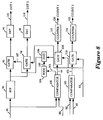
- FIG 8 is a block diagram of a circuit for eliminating highly bright objects from the evaluation function and for focusing on any remaining normal objects contained within the image scene.
- the circuit illustrated is contained within the AF IC 36.
- a band pass filter (BPF) 90 is coupled to receive the luminance signal 46 from the camera signal processor 34. The BPF 90 extracts the high frequency components of the luminance signal 46.
- a gate circuit 92 is coupled to receive the output of the BPF 90.
- the gate circuit 92 is also coupled to receive a control signal 107 from an AND circuit 106.
- the control signal 107 causes the gate circuit 92 to block the output of the BPF 90 corresponding to a highly bright object.
- a detector circuit (DET) 96 is coupled to receive the output of the gate circuit 92.
- the DET 96 generates an evaluation function 116.
- the evaluation function 116 reflects the high frequency component of the luminance signal 46 passed by the BPF 90 and the gate circuit 92.
- the DET 96 generates an H peak function for the evaluation function 116.
- a gate circuit 94 is coupled to receive the output of the BPF 90, and the window control signal 62 from the AF microcomputer 38.
- the gate circuit 94 blocks the output of the BPF 90 corresponding to areas of the image scene outside the evaluation window.
- a detector circuit (DET) 98 is coupled to receive the output of the gate circuit 94.
- the DET 98 generates an evaluation function 118, which reflects the high frequency component of the luminance signal 46 passed by the BPF 90 and the gate circuit 94.
- the DET 98 implements an H peak function for the evaluation function 118.
- a comparator circuit 100 is coupled to receive the luminance signal 46 from the camera signal processor 34.
- the comparator circuit 100 also receives the reference signal 86 from the AF microcomputer 38.
- the comparator circuit 100 compares the luminance signal 46 with the reference signal 86.
- the comparator circuit 100 generates a pulse signal 99 if the luminance signal 46 has a greater magnitude than the reference signal 86.
- a gate circuit 108 is coupled to receive the pulse signal 99 from the comparator circuit 100.
- the gate circuit 108 is also coupled to receive the window control signal 62 from the AF microcomputer 38.
- the gate circuit 108 blocks the pulse signal 99 for areas of the image scene outside the evaluation window.
- a counter circuit 112 receives the pulse signal 99 from the gate circuit 108.
- the counter circuit 112 generates a count signal 120, which is transmitted to the AF microcomputer 38.
- the count signal 120 indicates the number of pixels within the evaluation window having a magnitude of the luminance signal 46 greater than the reference signal 86.
- a comparator circuit 102 is coupled to receive the luminance signal 46 from the camera signal processor 34, and the reference signal 88 from the AF microcomputer 38. The comparator circuit 102 generates a pulse signal 103 if the luminance signal 46 has a greater magnitude than the reference signal 88.
- a gate circuit 110 is coupled to receive the pulse signal 103 from the comparator 102, and the window control signal 62 from the AF microcomputer 38. The gate circuit 110 blocks the pulse signal 103 for areas of the image scene outside the evaluation window.
- a counter circuit 114 generates a count signal 122, which indicates the number of pixels within the evaluation window having a magnitude of the luminance signal 46 greater than the reference signal 88.
- a WIDE circuit 104 receives a pulse signal 101 from the comparator 100.
- the comparator circuit 100 generates the pulse signal 101 if the luminance signal 46 has a greater magnitude than the reference signal 86.
- the WIDE circuit 104 generates a wide pulse 105 by increasing the width of the pulse signal 101.
- the AND circuit 106 is coupled to receive the wide pulse 105.
- the AND circuit 106 is also coupled to receive the window control signal 62 from the AF microcomputer 38.
- the AND circuit 106 generates the control signal 107 for the gate circuit 92.
- the control signal 107 causes the gate circuit 92 to block the output of the BPF 90 for areas of the evaluation window containing highly bright objects.
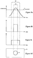
- Figures 9a-9d illustrate the functions of the WIDE circuit 104 and the AND circuit 106 to eliminate highly bright objects from the luminance signal 46.
- the AF microcomputer 38 sets the reference signal 86 to a saturation threshold value l threshold .
- the comparator 100 generates the pulse signal 101 for portions of the luminance signal 46 that exceed l threshold .
- the WIDE circuit 104 generates the wide pulse 105 by increasing the width of the pulse signal 101 by a time value DELTA T.
- the AND circuit 106 generates the control signal 107 as the logical product of the wide pulse 105 and the window control signal 62.
- the control signal 107 causes the gate circuit 92 to block the output of the BPF 90.
- Figure 9d illustrates an example highly bright object 130 positioned within an evaluation window 132.
- the highly bright object 130 is rendered on the CCD array 32 at a focus position of the optical lens system 30 that yields a blurred image.
- Figure 9a shows an example of the luminance signal 46 corresponding to a horizontal scan line of the evaluation window 132. As shown, the highly bright object 130 causes the luminance signal 46 to exceed l threshold .
- Figure 9b illustrates the pulse signal 101 generated by the comparator 100. The pulse signal 101 corresponds to a portion 136 of the luminance signal 46 that exceeds l threshold .
- Figure 9c illustrates the wide pulse 105 generated by the WIDE circuit 104.
- the wide pulse 105 corresponds to a portion 138 of the luminance signal 46 extending on both sides of the luminance signal 46.
- the wide pulse 105 when merged with the window control signal 62 causes the gate circuit 92 to mask the portion 138 of the luminance signal 46 from contributing to the evaluation function 116.
- the DET 96 generates the evaluation function 116 without the contribution of the highly bright object 130.
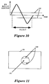
- Figure 10 illustrates a method for selecting the DELTA T for the WIDE circuit 104.
- a graph of the impulse response of the BPF 90 for one embodiment is shown.
- a pair of cutting lines 140 are placed at positions to intersect the impulse response at less than 20 percent of the absolute peak value. As shown on the graph, the intersection between the cutting lines 140 and the impulse response of the BPF 90 determine the DELTA T.
- Figure 11 illustrates an area 136 of the highly bright object 130 eliminated by the WIDE circuit 104 and the AND circuit 106.
- the area 136 is masked by the gate circuit 92.
- High frequency components of the luminance signal 46 corresponding to the area 136 do not contribute to the evaluation function 116.
- an area 134 of the highly bright object is not eliminated from the evaluation function 116.
- the effect of the area 134 on the evaluation function 116 depends on the method employed by the DET 96 to generate the evaluation function 116.
- the area 134 does not significantly contribute to the evaluation function 116. However, if the DET 96 determines a peak value of high frequency components of the luminance signal 46 over the entire evaluation window 132, then the area 134 can dominate the evaluation signal 116. In the later case, the area 134 should be eliminated.
- Figures 12a - 12b illustrate a method and apparatus for eliminating the highly bright objects from the evaluation function for one embodiment.
- Figure 12a is a block diagram of a circuit for eliminating the area 134 of the highly bright object 130 from the evaluation function 116.
- a delay circuit 160 is coupled to receive and delay the output of the BPF 90.
- the delay circuit 160 is comprised of a series of delay elements labeled "H". Each of the delay elements causes a delay equivalent to one horizontal scan line of the CCD array 32.
- a delay wide circuit 170 is coupled to received the wide pulse 105 from the WIDE circuit 104.
- the delay wide circuit 170 is comprised of an OR gate 171 and a set of delay elements labeled "H".
- the inputs to the OR gate 171 are the wide pulse 105 and the outputs of the delay elements, which are successive delays of the wide pulse 105.
- Figure 12b shows the area 182 of the evaluation window 132 eliminated from the evaluation function 116.
- a vertical distance between the highly bright object 130 and the top of the eliminated area 182 comprises "N" horizontal scan lines.
- the number of horizontal scan lines N equals the number of delay elements H contained in the delay circuit 160.
- the number of delay elements H contained in the delay wide circuit 170 equals 2N.
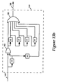
- Figures 13a - 13c illustrate a method and apparatus for eliminating the highly bright objects from the evaluation function for an alternative embodiment.
- Figure 13a is a block diagram of a circuit for eliminating the area 134 of the highly bright object 130 from the evaluation function 116.
- a series of 2N delay elements labeled "H" are coupled to receive and delay the output of the BPF 90.
- a series of N adjacent line delay wide circuits, such as the adjacent line delay circuit 180, are coupled to received the wide pulse 105 from the WIDE circuit 104.
- Figure 13b illustrates the adjacent line delay circuit 180, which is comprised of an OR gate 181, an AND gate 182, and a set of delay elements labeled "H".
- the adjacent line delay circuit 180 is coupled to receive the wide pulse 105.
- the wide pulse 105 is gated and delayed as shown to generate an adjacent line delay pulse 188.
- Each of the adjacent tine delay circuits eliminates part of an adjacent line.
- the set of adjacent line delay circuits shown in Figure 13a eliminates N adjacent lines from the evaluation function 116.
- Figure 13c shows an area 184 of the evaluation window 132 eliminated from the evaluation function 116 for the alternative embodiment.
- Figure 14 illustrates another alternative embodiment for eliminating highly bright objects from the evaluation function, wherein the luminance signal 46 is stored in a memory circuit 190.
- the memory circuit 190 is coupled to receive the luminance signal 46 from the CCD array 32.
- the memory circuit 190 stores the luminance signal 46 for subsequent transfer to the BPF 90.
- the luminance signal 46 is delayed while being transferred from the memory circuit 190 to the BPF 90.
- the delay wide circuit 170 is coupled to received the wide pulse 105 from the WIDE circuit 104.
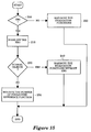
- Figure 15 is a flow diagram illustrating a method for automatically focusing video cameras wherein the image scene may contain highly bright objects.
- the image scene is tested for highly bright objects. If no highly bright objects are detected, then control proceeds to block 220.
- the AF microcomputer 38 adjusts the optical lens system 30 to maximize the evaluation function since the image scene contains normal objects only.
- control proceeds to block 210.
- the highly bright objects are masked off from the luminance signal in order to detect normal objects in the image scene.
- the image scene is tested for normal objects. If no normal objects are detected, then control proceeds to block 250.
- the AF microcomputer 38 adjusts the optical lens system 30 to minimize the number of the pixels over reference function since the image scene contains only highly bright objects.
- the AF microcomputer 38 adjusts the optical lens system 30 to maximize the evaluation function since highly bright objects are masked from the luminance signal.
- Figure 16 is a flow diagram for one embodiment of the present method and apparatus for automatically focusing video cameras, wherein the image scene may contain highly bright objects.
- the AF microcomputer 38 sets the reference signals 86 and 88 to generate the count signal 120 (COUNT1) and the count signal 122 (COUNT2).
- the AF microcomputer 38 calculates the ratio R, which equals COUNT2 divided by COUNT1 for the current focus position of the optical lens system 30.
- the AF microcomputer 38 determines R threshold in the manner previously discussed, and compares the ratio R to R threshold . If the ratio R is not greater than R threshold , then control proceeds to block 340 since the evaluation window of the image scene does not contain highly bright objects. At block 340, the AF microcomputer 38 adjusts the focus of the lens system 30 to maximize the evaluation function 118 (DET2).
- control proceeds to block 330 since the evaluation window of the image scene contains highly bright objects.
- the AF microcomputer 38 sets the reference signal 86 to generate the evaluation function 116 (DET1) and the evaluation function 118 (DET2).
- the evaluation function DET1 is generated without contribution from the highly bright objects, and the evaluation function DET2 is generated with the contribution of the highly bright objects.
- the AF microcomputer 38 calculates the ratio r, which equals DET1 divided by DET2 for the current focus position of the optical lens system 30.
- the AF microcomputer 38 compares the ratio r to r threshold . If the ratio r is not less than r threshold , then control proceeds to block 380 since the evaluation window of the image scene contains normal objects.
- the AF microcomputer 38 adjusts the focus of the lens system 30 to maximize the evaluation function 116 (DET1).
- control proceeds to block 370 since the evaluation window of the image scene does not contain normal objects.
- the AF microcomputer 38 adjusts the focus of the lens system 30 to minimize the count signal COUNT1 in order to focus on the highly bright objects.
Landscapes
- Engineering & Computer Science (AREA)
- Physics & Mathematics (AREA)
- Multimedia (AREA)
- Signal Processing (AREA)
- Computer Vision & Pattern Recognition (AREA)
- General Physics & Mathematics (AREA)
- Optics & Photonics (AREA)
- Automatic Focus Adjustment (AREA)
- Focusing (AREA)
Applications Claiming Priority (2)
| Application Number | Priority Date | Filing Date | Title |
|---|---|---|---|
| US937053 | 1992-08-27 | ||
| US07/937,053 US5416518A (en) | 1992-08-27 | 1992-08-27 | Camera auto focus system |
Publications (3)
| Publication Number | Publication Date |
|---|---|
| EP0586047A2 true EP0586047A2 (de) | 1994-03-09 |
| EP0586047A3 EP0586047A3 (de) | 1994-11-17 |
| EP0586047B1 EP0586047B1 (de) | 1998-09-30 |
Family
ID=25469415
Family Applications (1)
| Application Number | Title | Priority Date | Filing Date |
|---|---|---|---|
| EP93304778A Expired - Lifetime EP0586047B1 (de) | 1992-08-27 | 1993-06-18 | Automatische Fokussierung für Kameras |
Country Status (4)
| Country | Link |
|---|---|
| US (2) | US5416518A (de) |
| EP (1) | EP0586047B1 (de) |
| JP (1) | JP3685808B2 (de) |
| DE (1) | DE69321317T2 (de) |
Families Citing this family (17)
| Publication number | Priority date | Publication date | Assignee | Title |
|---|---|---|---|---|
| JP3106006B2 (ja) * | 1992-06-24 | 2000-11-06 | キヤノン株式会社 | 電子スチルカメラ |
| EP0605240B1 (de) * | 1992-12-28 | 2002-05-02 | Canon Kabushiki Kaisha | Integrierte Einzel-Chip-Schaltung zur Fokussierregelung |
| JP3752510B2 (ja) * | 1996-04-15 | 2006-03-08 | イーストマン コダック カンパニー | 画像の自動被写体検出方法 |
| JP3338322B2 (ja) | 1997-02-25 | 2002-10-28 | 三洋電機株式会社 | オートフォーカスカメラ |
| JPH11271600A (ja) * | 1998-03-25 | 1999-10-08 | Minolta Co Ltd | 距離検出装置 |
| JP3709294B2 (ja) * | 1998-11-18 | 2005-10-26 | 株式会社リコー | 自動焦点検出装置 |
| US6812968B1 (en) | 1998-12-31 | 2004-11-02 | Lucent Technologies Inc. | Camera with configurable focus area |
| JP3986988B2 (ja) * | 2002-09-27 | 2007-10-03 | 富士フイルム株式会社 | 自動焦点調節方法および装置 |
| JP4265233B2 (ja) * | 2003-02-13 | 2009-05-20 | 株式会社ニコン | カメラ |
| JP4647885B2 (ja) * | 2003-02-17 | 2011-03-09 | 株式会社ニコン | カメラ |
| JP2004309739A (ja) * | 2003-04-07 | 2004-11-04 | Canon Inc | 焦点検出装置 |
| JP2007072095A (ja) * | 2005-09-06 | 2007-03-22 | Sony Corp | 撮像方法および撮像装置 |
| JP5100484B2 (ja) * | 2008-04-15 | 2012-12-19 | Juki株式会社 | 自動焦点調整方法 |
| JP5950679B2 (ja) * | 2012-05-07 | 2016-07-13 | キヤノン株式会社 | 焦点検出装置、撮像装置及び焦点検出方法 |
| US9354489B2 (en) | 2014-02-10 | 2016-05-31 | Raytheon Company | Robust autofocus algorithm for multi-spectral imaging systems |
| KR102218877B1 (ko) * | 2014-06-03 | 2021-02-24 | 한화테크윈 주식회사 | 이미지 프로세서 및 이를 포함하는 촬영 장치 |
| JP7535860B2 (ja) * | 2020-02-27 | 2024-08-19 | 株式会社Screenホールディングス | 合焦位置検出方法、合焦位置検出装置および合焦位置検出用プログラム |
Family Cites Families (8)
| Publication number | Priority date | Publication date | Assignee | Title |
|---|---|---|---|---|
| US4780766A (en) * | 1987-05-29 | 1988-10-25 | Eastman Kodak Company | Still video camera having effective imager sensitivity optimized for electronic preview |
| US5070408A (en) * | 1989-05-19 | 1991-12-03 | Sony Corporation | Focusing apparatus and digital filters for use therewith |
| JP2847805B2 (ja) * | 1989-10-11 | 1999-01-20 | ソニー株式会社 | フォーカス制御回路 |
| JP2822256B2 (ja) * | 1990-02-15 | 1998-11-11 | ソニー株式会社 | ビデオカメラの露光補正装置 |
| US5235428A (en) * | 1990-02-21 | 1993-08-10 | Sony Corporation | Auto-focus system for video camera |
| JPH03243071A (ja) * | 1990-02-21 | 1991-10-30 | Sony Corp | オートフォーカス回路 |
| US5200828A (en) * | 1990-03-19 | 1993-04-06 | Sam Jung Co., Ltd. | Autofocusing device for use in a video camera and an autofocusing method thereof |
| JP3103587B2 (ja) * | 1990-04-25 | 2000-10-30 | オリンパス光学工業株式会社 | 自動合焦装置 |
-
1992
- 1992-08-27 US US07/937,053 patent/US5416518A/en not_active Expired - Lifetime
-
1993
- 1993-06-18 EP EP93304778A patent/EP0586047B1/de not_active Expired - Lifetime
- 1993-06-18 DE DE69321317T patent/DE69321317T2/de not_active Expired - Lifetime
- 1993-07-27 JP JP18484893A patent/JP3685808B2/ja not_active Expired - Lifetime
-
1994
- 1994-08-31 US US08/299,163 patent/US5539462A/en not_active Expired - Lifetime
Also Published As
| Publication number | Publication date |
|---|---|
| EP0586047A3 (de) | 1994-11-17 |
| JP3685808B2 (ja) | 2005-08-24 |
| JPH06209425A (ja) | 1994-07-26 |
| DE69321317D1 (de) | 1998-11-05 |
| EP0586047B1 (de) | 1998-09-30 |
| US5416518A (en) | 1995-05-16 |
| US5539462A (en) | 1996-07-23 |
| DE69321317T2 (de) | 1999-04-08 |
Similar Documents
| Publication | Publication Date | Title |
|---|---|---|
| EP0586047B1 (de) | Automatische Fokussierung für Kameras | |
| US5715483A (en) | Automatic focusing apparatus and method | |
| US20110080498A1 (en) | Image pickup apparatus | |
| JPH09200597A (ja) | 自動焦点検出装置 | |
| GB2257544A (en) | Camera tracking | |
| US5442397A (en) | Image sensing apparatus | |
| US6124890A (en) | Automatic focus detecting device | |
| US6507367B2 (en) | Image pickup apparatus for varying filter characteristics for focus adjustment | |
| JPH067212B2 (ja) | ズームレンズシステム | |
| US5638122A (en) | Video camera apparatus and automatic focusing circuit | |
| US20010010558A1 (en) | Image pickup apparatus having focus detection area size dependent on aspect ratio | |
| US5798793A (en) | Automatic focusing device capable of detecting panning | |
| JP3180486B2 (ja) | 自動焦点調節装置およびビデオカメラ | |
| EP0572163B1 (de) | Autofokus-Vorrichtung | |
| US5652925A (en) | Image sensor system and auto-focus detection device | |
| US5739858A (en) | Automatic focusing device using a plurality of different frequency components extracted at the same point | |
| JP2832029B2 (ja) | 自動焦点整合装置 | |
| JPH0754968B2 (ja) | 合焦検出装置 | |
| EP0774863A1 (de) | Fokussierungsmethode und videokamera | |
| KR0179067B1 (ko) | 비디오 포커싱 방식에서의 자동 포커싱장치 및 방법 | |
| JP2715441B2 (ja) | 撮像装置 | |
| JP2611237B2 (ja) | 自動合焦装置 | |
| KR970004183B1 (ko) | 비디오 카메라의 화면 처리 방법 | |
| JPH04283713A (ja) | 自動焦点検出装置 | |
| KR200198119Y1 (ko) | 전하결합소자 카메라 |
Legal Events
| Date | Code | Title | Description |
|---|---|---|---|
| PUAI | Public reference made under article 153(3) epc to a published international application that has entered the european phase |
Free format text: ORIGINAL CODE: 0009012 |
|
| AK | Designated contracting states |
Kind code of ref document: A2 Designated state(s): DE FR GB |
|
| PUAL | Search report despatched |
Free format text: ORIGINAL CODE: 0009013 |
|
| AK | Designated contracting states |
Kind code of ref document: A3 Designated state(s): DE FR GB |
|
| 17P | Request for examination filed |
Effective date: 19950406 |
|
| 17Q | First examination report despatched |
Effective date: 19970218 |
|
| GRAG | Despatch of communication of intention to grant |
Free format text: ORIGINAL CODE: EPIDOS AGRA |
|
| GRAG | Despatch of communication of intention to grant |
Free format text: ORIGINAL CODE: EPIDOS AGRA |
|
| GRAH | Despatch of communication of intention to grant a patent |
Free format text: ORIGINAL CODE: EPIDOS IGRA |
|
| GRAH | Despatch of communication of intention to grant a patent |
Free format text: ORIGINAL CODE: EPIDOS IGRA |
|
| GRAA | (expected) grant |
Free format text: ORIGINAL CODE: 0009210 |
|
| AK | Designated contracting states |
Kind code of ref document: B1 Designated state(s): DE FR GB |
|
| REF | Corresponds to: |
Ref document number: 69321317 Country of ref document: DE Date of ref document: 19981105 |
|
| ET | Fr: translation filed | ||
| PLBE | No opposition filed within time limit |
Free format text: ORIGINAL CODE: 0009261 |
|
| STAA | Information on the status of an ep patent application or granted ep patent |
Free format text: STATUS: NO OPPOSITION FILED WITHIN TIME LIMIT |
|
| 26N | No opposition filed | ||
| REG | Reference to a national code |
Ref country code: GB Ref legal event code: IF02 |
|
| PGFP | Annual fee paid to national office [announced via postgrant information from national office to epo] |
Ref country code: DE Payment date: 20120622 Year of fee payment: 20 |
|
| PGFP | Annual fee paid to national office [announced via postgrant information from national office to epo] |
Ref country code: GB Payment date: 20120622 Year of fee payment: 20 Ref country code: FR Payment date: 20120705 Year of fee payment: 20 |
|
| REG | Reference to a national code |
Ref country code: DE Ref legal event code: R071 Ref document number: 69321317 Country of ref document: DE |
|
| REG | Reference to a national code |
Ref country code: GB Ref legal event code: PE20 Expiry date: 20130617 |
|
| PG25 | Lapsed in a contracting state [announced via postgrant information from national office to epo] |
Ref country code: DE Free format text: LAPSE BECAUSE OF EXPIRATION OF PROTECTION Effective date: 20130619 Ref country code: GB Free format text: LAPSE BECAUSE OF EXPIRATION OF PROTECTION Effective date: 20130617 |