EP0586078A2 - Gas-Durchflussregler - Google Patents
Gas-Durchflussregler Download PDFInfo
- Publication number
- EP0586078A2 EP0586078A2 EP93305887A EP93305887A EP0586078A2 EP 0586078 A2 EP0586078 A2 EP 0586078A2 EP 93305887 A EP93305887 A EP 93305887A EP 93305887 A EP93305887 A EP 93305887A EP 0586078 A2 EP0586078 A2 EP 0586078A2
- Authority
- EP
- European Patent Office
- Prior art keywords
- chamber
- piston
- gas
- pressure relief
- regulator
- Prior art date
- Legal status (The legal status is an assumption and is not a legal conclusion. Google has not performed a legal analysis and makes no representation as to the accuracy of the status listed.)
- Granted
Links
- 238000007789 sealing Methods 0.000 claims description 11
- 239000007789 gas Substances 0.000 description 48
- 239000007787 solid Substances 0.000 description 6
- 230000003466 anti-cipated effect Effects 0.000 description 1
- QVGXLLKOCUKJST-UHFFFAOYSA-N atomic oxygen Chemical compound [O] QVGXLLKOCUKJST-UHFFFAOYSA-N 0.000 description 1
- 230000006835 compression Effects 0.000 description 1
- 238000007906 compression Methods 0.000 description 1
- 238000010276 construction Methods 0.000 description 1
- 230000006866 deterioration Effects 0.000 description 1
- 230000007257 malfunction Effects 0.000 description 1
- 238000004519 manufacturing process Methods 0.000 description 1
- 230000004048 modification Effects 0.000 description 1
- 238000012986 modification Methods 0.000 description 1
- 239000001301 oxygen Substances 0.000 description 1
- 229910052760 oxygen Inorganic materials 0.000 description 1
- 230000029058 respiratory gaseous exchange Effects 0.000 description 1
- 238000009420 retrofitting Methods 0.000 description 1
- 238000006467 substitution reaction Methods 0.000 description 1
Images
Classifications
-
- G—PHYSICS
- G05—CONTROLLING; REGULATING
- G05D—SYSTEMS FOR CONTROLLING OR REGULATING NON-ELECTRIC VARIABLES
- G05D16/00—Control of fluid pressure
- G05D16/04—Control of fluid pressure without auxiliary power
- G05D16/10—Control of fluid pressure without auxiliary power the sensing element being a piston or plunger
-
- Y—GENERAL TAGGING OF NEW TECHNOLOGICAL DEVELOPMENTS; GENERAL TAGGING OF CROSS-SECTIONAL TECHNOLOGIES SPANNING OVER SEVERAL SECTIONS OF THE IPC; TECHNICAL SUBJECTS COVERED BY FORMER USPC CROSS-REFERENCE ART COLLECTIONS [XRACs] AND DIGESTS
- Y10—TECHNICAL SUBJECTS COVERED BY FORMER USPC
- Y10T—TECHNICAL SUBJECTS COVERED BY FORMER US CLASSIFICATION
- Y10T137/00—Fluid handling
- Y10T137/2496—Self-proportioning or correlating systems
- Y10T137/2559—Self-controlled branched flow systems
- Y10T137/2574—Bypass or relief controlled by main line fluid condition
- Y10T137/2605—Pressure responsive
- Y10T137/2607—With pressure reducing inlet valve
- Y10T137/261—Relief port through common sensing means
-
- Y—GENERAL TAGGING OF NEW TECHNOLOGICAL DEVELOPMENTS; GENERAL TAGGING OF CROSS-SECTIONAL TECHNOLOGIES SPANNING OVER SEVERAL SECTIONS OF THE IPC; TECHNICAL SUBJECTS COVERED BY FORMER USPC CROSS-REFERENCE ART COLLECTIONS [XRACs] AND DIGESTS
- Y10—TECHNICAL SUBJECTS COVERED BY FORMER USPC
- Y10T—TECHNICAL SUBJECTS COVERED BY FORMER US CLASSIFICATION
- Y10T137/00—Fluid handling
- Y10T137/7722—Line condition change responsive valves
- Y10T137/7781—With separate connected fluid reactor surface
- Y10T137/7793—With opening bias [e.g., pressure regulator]
- Y10T137/7794—With relief valve
-
- Y—GENERAL TAGGING OF NEW TECHNOLOGICAL DEVELOPMENTS; GENERAL TAGGING OF CROSS-SECTIONAL TECHNOLOGIES SPANNING OVER SEVERAL SECTIONS OF THE IPC; TECHNICAL SUBJECTS COVERED BY FORMER USPC CROSS-REFERENCE ART COLLECTIONS [XRACs] AND DIGESTS
- Y10—TECHNICAL SUBJECTS COVERED BY FORMER USPC
- Y10T—TECHNICAL SUBJECTS COVERED BY FORMER US CLASSIFICATION
- Y10T137/00—Fluid handling
- Y10T137/7722—Line condition change responsive valves
- Y10T137/7781—With separate connected fluid reactor surface
- Y10T137/7793—With opening bias [e.g., pressure regulator]
- Y10T137/7808—Apertured reactor surface surrounds flow line
Definitions
- This invention relates to a gas flow control regulator for receiving gas from a high pressure source and supplying the gas at a low pressure to the user.
- gas flow control regulators have particular application in the medical field, for example in hospitals where oxygen or other breathing gas from a high pressure gas cylinder is to be supplied through tubes capable of withstanding only pressure below 200 pounds for use by a patient.
- Such gas flow control regulators are used in association with a pressure relief device which has conventionally been a separate device from the gas flow control regulator with the result that both the regulator and the pressure relief device have to be connected to the outlet from the gas cylinder.
- a combined gas flow control regulator and pressure relief valve is disclosed in U.S. Patent No. 4,655,246. It is an object of the present invention to provide a gas flow control regulator which includes a pressure relief valve within the same body as the regulator but which has advantages in comparison with the device of U.S. Patent No. 4,655,246.
- a gas flow control regulator comprising a regulator body, a piston including a piston head and a piston rod within the regulator body, the piston head and the piston rod both being in sealing engagement with portions of the regulator body to divide the interior of the regulator body into three chambers, a first chamber which is a sealed chamber between the piston head and one end of the regulator body, a second chamber between the piston head and the portion of the regulator body within which the piston rod is sealingly engaged and a third chamber beyond the piston rod, an aperture in the regulator body connecting the second chamber to atmosphere, a gas inlet communicating with the third chamber for passing gas at high pressure from a source thereof to the third chamber, the piston having a valve seat thereon for sealing against the gas inlet in the third chamber, a gas conduit within the piston rod connecting the third chamber to the first chamber, a gas outlet from the third chamber for passing low pressure gas from the regulator body to a user, a pressure relief valve member including a sleeve sealingly engaged with the piston rod within the second chamber and slidable
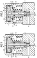
- a gas flow control regulator having a regulator body comprising portions 1 and 2, portion being a substantially solid portion and portion 2 being a substantially hollow cap secured to the substantially solid portion 1.
- a piston including a piston head 3 and a piston rod 4.
- the piston head 3 is in sealing engagment through o-ring 5 with the interior surface of portion 2 of the regulator body and the piston rod 4 is in sealing engagement through o-ring 6 with a channel 7 formed in the substantially solid portion 1 of the regulator body.
- the interior of the regulator body is thus divided into three chambers , a first chamber 8 between the piston head 3 and the end of the regulator body defined by the portion 2, a second chamber 9 between the piston head 3 and the substantially solid portion 1 of the regulator body and a third chamber 10 within the solid portion 1 of the regulator body below the end of the piston rod 4.
- a gas inlet 11 communicates with the third chamber 10 for passing gas at high pressure from a source thereof such as a gas cylinder to the third chamber 10.
- the portion 1 of the regulator body includes means connecting the regulator body to the outlet of gas cylinder which is conventional and has been omitted from the figures of the accompanying drawings.
- the gas inlet 11 to the third chamber 10 terminates in a gas jet 12 which is engaged by a valve seat 13 mounted on the piston rod 4 to prevent entry of gas from the gas cylinder into the third chamber 10 when no low pressure gas is being withdrawn from the third chamber 10 through outlet 15.
- a pressure relief member comprises a sleeve 18 of a diameter such as to be capable of sliding on the external surface of piston rod 4 and in sealing engagement with the piston rod 4 as a result of the presence of o-ring 19.
- the pressure relief member additionally includes a flange 20 which is in sealing engagement with the surface of the piston head 3 bounding the second chamber 9 through 0-ring 21.
- the piston head 3 has an aperture 22 extending through it from the first chamber 8 to the second chamber 9, this aperture 22 being closed as shown in Figure 1 during normal operation of the gas flow control regulator.
- the second chamber 9 is vented to atmosphere through apertures 23 in the walls of portion 2 of the regulator body.
- a coiled compression spring 24 bears against the portion 1 of the regulator body and against the flange 20 of the pressure relief member to urge the pressure relief member towards the piston head 3 to maintain the pressure relief member in contact with the piston head 3 so that the piston and the pressure relief member move as one unit in normal operation of the gas flow control regulator, that is to say in the absence of undesired excess pressure.
- valve member 14 and piston are raised a small distance from the gas inlet 12 to permit gas to pass from the high pressure source into the third chamber 10 and through the passage 17 and gas conduit 16 to the first chamber 8.
- Aperture 22 being closed by the flange 20 of the pressure relief member, a pressure is created in the first chamber 8 which acts on the piston head 3 to counter balance the forces exerted on the piston by the spring 24 and the gas pressure in the third chamber 10 which acts on the small areas of the valve seat 13 and piston rod 4. Accordingly gas at a low pressure is provided through outlet 15 causing the piston to move up and down to open and close the gas jet 12 in the third chamber 10.
- the spring 24 can return the pressure relief member to the sealing position in which the flange 20 of the pressure relief member again closes the aperture 22 and the second chamber 9 is sealed from the first chamber 8.
- the arrangement in accordance with the present invention provides a pressure relief member which moves relative to the piston totally independently of the motion of the piston.
- the pressure relief member will therefore still operate to provide relief of excess pressure when the piston is unable to move due, for example, to the o-ring 6 seizing up.
- the piston is directly in contact with the portion 1 of the regulator body thereby improving the alignment of the valve seat 13 on the piston with the gas jet 12. Relative movement between the gas jet 12 and valve seat 13 is thus reduced and sealing efficency is maintained longer than in the previously proposed device.
- Alignment of the sealing area of o-ring 21 and the piston head 3 is independent of the securing of the cap portion 2 of the regulator body to the substantially solid portion 1 by screw threads. The alignment is therefore more consistent and allows lower tolerances in manufacture without introducing deterioration in pressure relief performance.
- the construction of the gas flow control regulator of the present invention is such that existing piston type regulators may be converted into gas flow control regulators including pressure relief members by simple substitution of a piston and pressure relief valve member as herein described. Such retrofitting of existing piston type regulators cannot be done with the device of U.S. Patent No. 4,655,246 without modification of the regulator body.
Landscapes
- Physics & Mathematics (AREA)
- Fluid Mechanics (AREA)
- General Physics & Mathematics (AREA)
- Engineering & Computer Science (AREA)
- Automation & Control Theory (AREA)
- Control Of Fluid Pressure (AREA)
- Safety Valves (AREA)
Applications Claiming Priority (2)
| Application Number | Priority Date | Filing Date | Title |
|---|---|---|---|
| GB9216648 | 1992-08-05 | ||
| GB9216648A GB2269441B (en) | 1992-08-05 | 1992-08-05 | A gas flow control regulator |
Publications (3)
| Publication Number | Publication Date |
|---|---|
| EP0586078A2 true EP0586078A2 (de) | 1994-03-09 |
| EP0586078A3 EP0586078A3 (de) | 1995-01-18 |
| EP0586078B1 EP0586078B1 (de) | 1998-04-22 |
Family
ID=10719878
Family Applications (1)
| Application Number | Title | Priority Date | Filing Date |
|---|---|---|---|
| EP93305887A Expired - Lifetime EP0586078B1 (de) | 1992-08-05 | 1993-07-26 | Gas-Durchflussregler |
Country Status (5)
| Country | Link |
|---|---|
| US (1) | US5307834A (de) |
| EP (1) | EP0586078B1 (de) |
| DE (1) | DE69318085T2 (de) |
| ES (1) | ES2114591T3 (de) |
| GB (1) | GB2269441B (de) |
Families Citing this family (26)
| Publication number | Priority date | Publication date | Assignee | Title |
|---|---|---|---|---|
| DE69602905T2 (de) * | 1995-11-16 | 2000-01-27 | The Boc Group Plc, Windlesham | Druckreduzierventil |
| US6647982B1 (en) * | 1998-06-29 | 2003-11-18 | Zaiser Lenoir E. | Gas flow device |
| US6257275B1 (en) * | 2000-04-17 | 2001-07-10 | Liberty Group | Pressure reducing valve |
| EP1303718B1 (de) | 2000-05-25 | 2006-10-11 | ASCO Controls, L.P. | Druckregulierender kolben mit eingebautem überdruckventil |
| DE10219007B4 (de) * | 2002-04-27 | 2004-07-29 | DRäGER AEROSPACE GMBH | Reduzierventil für Druckgas |
| US7757703B2 (en) * | 2006-07-12 | 2010-07-20 | Cameron International Corporation | Device for regulating pressure |
| US7520297B2 (en) * | 2006-07-12 | 2009-04-21 | Cameron International Corporation | Pressure regulator device and system |
| JP4721076B2 (ja) * | 2008-07-08 | 2011-07-13 | Smc株式会社 | 減圧装置 |
| IT1390876B1 (it) * | 2008-07-31 | 2011-10-19 | Cavagna Group S P A Con Socio Unico | Gruppo valvolare regolatore di pressione per recipienti destinati a contenere fluidi compressi |
| US8973603B2 (en) * | 2009-02-17 | 2015-03-10 | Carefusion 2200, Inc. | Gas flow regulating device |
| GB2469622B (en) * | 2009-04-20 | 2011-03-16 | Rolls Royce Plc | A fuel distributor valve |
| US20110056573A1 (en) * | 2009-09-09 | 2011-03-10 | Mu-Sung Huang | Pressure reducing device of a high pressure vessel |
| FR2949812B1 (fr) * | 2009-09-10 | 2012-03-30 | Peugeot Citroen Automobiles Sa | Dispositif et procede de regulation de l'injection d'une quantite de reducteur en phase gaz |
| GB201006347D0 (en) | 2010-04-16 | 2010-06-02 | Linde Ag | Gas pressure control valve |
| US20150068621A1 (en) * | 2013-09-09 | 2015-03-12 | Timothy Brian Conner | Medical Gas Manifold |
| EP2921924B1 (de) * | 2014-03-21 | 2018-09-19 | Asco Numatics GmbH | Vorrichtung zur Bereitstellung eines Fluids mit geregeltem Ausgangsdruck |
| JP6433697B2 (ja) * | 2014-06-30 | 2018-12-05 | 株式会社ネリキ | 導通方向規制弁機構体及びバルブ装置 |
| US20160032577A1 (en) * | 2014-07-29 | 2016-02-04 | Lavelle Industries, Inc. | Fill valve regulator and assembly |
| US9791067B2 (en) * | 2014-07-31 | 2017-10-17 | Steffes Corporation | Flare tip valve dampening |
| US20160097362A1 (en) * | 2014-10-06 | 2016-04-07 | Hamilton Sundstrand Corporation | Variable area orifice for an engine |
| US9879799B2 (en) | 2015-09-16 | 2018-01-30 | Cameron International Corporation | Pressure regulator |
| WO2017127730A1 (en) * | 2016-01-20 | 2017-07-27 | Ada Technologies, Inc. | Ultra-high pressure regulator and a method of using the same |
| EP3443246B1 (de) | 2016-04-12 | 2023-06-07 | Mobile I.V. Systems, LLC | Druckregelnde vorrichtung und system mit der druckregelnden vorrichtung |
| US11174956B2 (en) * | 2018-09-14 | 2021-11-16 | Ningbo Major Draft Beer Equipment Co., Ltd | Regulable pressure relief valve for a draft beer fresh-keeping keg |
| WO2020235504A1 (ja) * | 2019-05-18 | 2020-11-26 | 岩谷産業株式会社 | バルブ装置及びガス消費ユニット |
| USD1094704S1 (en) | 2024-01-08 | 2025-09-23 | Mobile I.V. Systems, LLC | Drip chamber |
Family Cites Families (7)
| Publication number | Priority date | Publication date | Assignee | Title |
|---|---|---|---|---|
| GB737198A (en) * | 1953-02-27 | 1955-09-21 | Dunlop Rubber Co | Pressure reducing valve |
| FR1224116A (fr) * | 1958-01-13 | 1960-06-22 | Renault | Détendeur de pression |
| US3348573A (en) * | 1965-04-19 | 1967-10-24 | Grove Valve & Regulator Co | Fluid pressure regulator having a guided pressure responsive member |
| US3522818A (en) * | 1966-12-12 | 1970-08-04 | Zaklady Mekh Precyzjnej | Pressure-reducing valve for breathing apparatus |
| US3848631A (en) * | 1970-10-26 | 1974-11-19 | Draft Systems | Beer keg protective device |
| US4020863A (en) * | 1975-10-09 | 1977-05-03 | Robertshaw Controls Company | Fluid pressure regulator construction |
| US4655246A (en) * | 1983-09-30 | 1987-04-07 | Essex Industries, Inc. | Regulated gas flow control valve |
-
1992
- 1992-08-05 GB GB9216648A patent/GB2269441B/en not_active Expired - Lifetime
-
1993
- 1993-07-26 DE DE69318085T patent/DE69318085T2/de not_active Expired - Lifetime
- 1993-07-26 ES ES93305887T patent/ES2114591T3/es not_active Expired - Lifetime
- 1993-07-26 EP EP93305887A patent/EP0586078B1/de not_active Expired - Lifetime
- 1993-08-02 US US08/100,304 patent/US5307834A/en not_active Expired - Lifetime
Also Published As
| Publication number | Publication date |
|---|---|
| ES2114591T3 (es) | 1998-06-01 |
| DE69318085D1 (de) | 1998-05-28 |
| EP0586078A3 (de) | 1995-01-18 |
| GB2269441A (en) | 1994-02-09 |
| GB2269441B (en) | 1996-01-24 |
| EP0586078B1 (de) | 1998-04-22 |
| US5307834A (en) | 1994-05-03 |
| GB9216648D0 (en) | 1992-09-16 |
| DE69318085T2 (de) | 1998-08-13 |
Similar Documents
| Publication | Publication Date | Title |
|---|---|---|
| US5307834A (en) | Gas flow control regulator | |
| AU625576B2 (en) | Respirator | |
| US4776561A (en) | Trigger control for air tool handle | |
| JP2630439B2 (ja) | 調整器 | |
| CA2298377A1 (en) | Fluid flow valve with variable flow rate | |
| EP0803669A3 (de) | Druckentlastungsvorrichtung für Druckbehälter | |
| US4421292A (en) | Air-operated oil pressure control valve | |
| CA2128953A1 (en) | Pilot stage for pressure control valves | |
| EP1031901A1 (de) | Regler | |
| CA2143114A1 (en) | Fluid Flow Check Valve | |
| US5520214A (en) | Regulator and fill valve | |
| AU1734192A (en) | Plug valve | |
| US5732735A (en) | Pressure reduction valve | |
| US4903726A (en) | Medical vacuum regulating cartridge | |
| GB2303199A (en) | Valve assemblies | |
| US5549107A (en) | Second stage scuba diving regulator | |
| EP1158226B1 (de) | Ladeventil für Gas | |
| US6382243B2 (en) | Pressure-reducing valve | |
| US6053192A (en) | Low operating force pressure regulator | |
| US5918623A (en) | Starting valve | |
| GB2144334A (en) | Combination venturi jet and exhalation valve assembly | |
| KR100300518B1 (ko) | 클러치배력장치의컨트롤밸브 | |
| EP0777074A2 (de) | Verbesserungen an Druckentlastungsventilen | |
| EP0050898B1 (de) | Druckregel- und Absperrventil | |
| EP0078644A2 (de) | Atemluft-Zufuhrregler |
Legal Events
| Date | Code | Title | Description |
|---|---|---|---|
| PUAI | Public reference made under article 153(3) epc to a published international application that has entered the european phase |
Free format text: ORIGINAL CODE: 0009012 |
|
| AK | Designated contracting states |
Kind code of ref document: A2 Designated state(s): DE ES FR IT |
|
| PUAL | Search report despatched |
Free format text: ORIGINAL CODE: 0009013 |
|
| AK | Designated contracting states |
Kind code of ref document: A3 Designated state(s): DE ES FR IT |
|
| 17P | Request for examination filed |
Effective date: 19950705 |
|
| 17Q | First examination report despatched |
Effective date: 19961218 |
|
| GRAG | Despatch of communication of intention to grant |
Free format text: ORIGINAL CODE: EPIDOS AGRA |
|
| GRAG | Despatch of communication of intention to grant |
Free format text: ORIGINAL CODE: EPIDOS AGRA |
|
| GRAH | Despatch of communication of intention to grant a patent |
Free format text: ORIGINAL CODE: EPIDOS IGRA |
|
| GRAH | Despatch of communication of intention to grant a patent |
Free format text: ORIGINAL CODE: EPIDOS IGRA |
|
| GRAA | (expected) grant |
Free format text: ORIGINAL CODE: 0009210 |
|
| AK | Designated contracting states |
Kind code of ref document: B1 Designated state(s): DE ES FR IT |
|
| ITF | It: translation for a ep patent filed | ||
| REF | Corresponds to: |
Ref document number: 69318085 Country of ref document: DE Date of ref document: 19980528 |
|
| REG | Reference to a national code |
Ref country code: ES Ref legal event code: FG2A Ref document number: 2114591 Country of ref document: ES Kind code of ref document: T3 |
|
| ET | Fr: translation filed | ||
| PLBE | No opposition filed within time limit |
Free format text: ORIGINAL CODE: 0009261 |
|
| STAA | Information on the status of an ep patent application or granted ep patent |
Free format text: STATUS: NO OPPOSITION FILED WITHIN TIME LIMIT |
|
| 26N | No opposition filed | ||
| REG | Reference to a national code |
Ref country code: FR Ref legal event code: TP |
|
| REG | Reference to a national code |
Ref country code: ES Ref legal event code: PC2A |
|
| PGFP | Annual fee paid to national office [announced via postgrant information from national office to epo] |
Ref country code: FR Payment date: 20120731 Year of fee payment: 20 Ref country code: DE Payment date: 20120727 Year of fee payment: 20 Ref country code: IT Payment date: 20120724 Year of fee payment: 20 Ref country code: ES Payment date: 20120726 Year of fee payment: 20 |
|
| REG | Reference to a national code |
Ref country code: DE Ref legal event code: R071 Ref document number: 69318085 Country of ref document: DE |
|
| PG25 | Lapsed in a contracting state [announced via postgrant information from national office to epo] |
Ref country code: DE Free format text: LAPSE BECAUSE OF EXPIRATION OF PROTECTION Effective date: 20130727 |
|
| REG | Reference to a national code |
Ref country code: ES Ref legal event code: FD2A Effective date: 20140925 |
|
| PG25 | Lapsed in a contracting state [announced via postgrant information from national office to epo] |
Ref country code: ES Free format text: LAPSE BECAUSE OF EXPIRATION OF PROTECTION Effective date: 20130727 |