EP0586286A1 - Drahtloses Übertragungssystem für medizinische Daten - Google Patents
Drahtloses Übertragungssystem für medizinische Daten Download PDFInfo
- Publication number
- EP0586286A1 EP0586286A1 EP93402090A EP93402090A EP0586286A1 EP 0586286 A1 EP0586286 A1 EP 0586286A1 EP 93402090 A EP93402090 A EP 93402090A EP 93402090 A EP93402090 A EP 93402090A EP 0586286 A1 EP0586286 A1 EP 0586286A1
- Authority
- EP
- European Patent Office
- Prior art keywords
- modulator
- signal
- transmission
- channel
- code
- Prior art date
- Legal status (The legal status is an assumption and is not a legal conclusion. Google has not performed a legal analysis and makes no representation as to the accuracy of the status listed.)
- Granted
Links
- 230000005540 biological transmission Effects 0.000 title claims abstract description 38
- 230000003321 amplification Effects 0.000 claims abstract description 14
- 238000003199 nucleic acid amplification method Methods 0.000 claims abstract description 14
- 238000001914 filtration Methods 0.000 claims abstract description 8
- 238000012545 processing Methods 0.000 claims abstract description 7
- 238000006243 chemical reaction Methods 0.000 claims abstract 2
- 230000005684 electric field Effects 0.000 claims description 3
- 230000006835 compression Effects 0.000 claims description 2
- 238000007906 compression Methods 0.000 claims description 2
- 239000010931 gold Substances 0.000 claims description 2
- 229910052737 gold Inorganic materials 0.000 claims description 2
- PCHJSUWPFVWCPO-UHFFFAOYSA-N gold Chemical compound [Au] PCHJSUWPFVWCPO-UHFFFAOYSA-N 0.000 claims 1
- 230000002085 persistent effect Effects 0.000 abstract 1
- 238000002565 electrocardiography Methods 0.000 description 13
- 238000012544 monitoring process Methods 0.000 description 7
- 230000000694 effects Effects 0.000 description 4
- 239000000969 carrier Substances 0.000 description 3
- 244000045947 parasite Species 0.000 description 3
- 238000000926 separation method Methods 0.000 description 3
- 238000012937 correction Methods 0.000 description 2
- 238000005259 measurement Methods 0.000 description 2
- 238000000034 method Methods 0.000 description 2
- 238000005070 sampling Methods 0.000 description 2
- 238000012360 testing method Methods 0.000 description 2
- 238000012549 training Methods 0.000 description 2
- 241000777300 Congiopodidae Species 0.000 description 1
- 240000005561 Musa balbisiana Species 0.000 description 1
- 235000018290 Musa x paradisiaca Nutrition 0.000 description 1
- 230000002457 bidirectional effect Effects 0.000 description 1
- 238000012512 characterization method Methods 0.000 description 1
- 239000004020 conductor Substances 0.000 description 1
- 125000004122 cyclic group Chemical group 0.000 description 1
- 230000007812 deficiency Effects 0.000 description 1
- 238000001514 detection method Methods 0.000 description 1
- 238000011161 development Methods 0.000 description 1
- 238000003745 diagnosis Methods 0.000 description 1
- 238000010586 diagram Methods 0.000 description 1
- 230000008034 disappearance Effects 0.000 description 1
- 230000000474 nursing effect Effects 0.000 description 1
- 230000000630 rising effect Effects 0.000 description 1
- 230000035900 sweating Effects 0.000 description 1
- XLYOFNOQVPJJNP-UHFFFAOYSA-N water Substances O XLYOFNOQVPJJNP-UHFFFAOYSA-N 0.000 description 1
- 210000000707 wrist Anatomy 0.000 description 1
Images



Classifications
-
- A—HUMAN NECESSITIES
- A61—MEDICAL OR VETERINARY SCIENCE; HYGIENE
- A61B—DIAGNOSIS; SURGERY; IDENTIFICATION
- A61B5/00—Measuring for diagnostic purposes; Identification of persons
- A61B5/0002—Remote monitoring of patients using telemetry, e.g. transmission of vital signals via a communication network
- A61B5/0004—Remote monitoring of patients using telemetry, e.g. transmission of vital signals via a communication network characterised by the type of physiological signal transmitted
- A61B5/0006—ECG or EEG signals
-
- Y—GENERAL TAGGING OF NEW TECHNOLOGICAL DEVELOPMENTS; GENERAL TAGGING OF CROSS-SECTIONAL TECHNOLOGIES SPANNING OVER SEVERAL SECTIONS OF THE IPC; TECHNICAL SUBJECTS COVERED BY FORMER USPC CROSS-REFERENCE ART COLLECTIONS [XRACs] AND DIGESTS
- Y10—TECHNICAL SUBJECTS COVERED BY FORMER USPC
- Y10S—TECHNICAL SUBJECTS COVERED BY FORMER USPC CROSS-REFERENCE ART COLLECTIONS [XRACs] AND DIGESTS
- Y10S128/00—Surgery
- Y10S128/901—Suppression of noise in electric signal
-
- Y—GENERAL TAGGING OF NEW TECHNOLOGICAL DEVELOPMENTS; GENERAL TAGGING OF CROSS-SECTIONAL TECHNOLOGIES SPANNING OVER SEVERAL SECTIONS OF THE IPC; TECHNICAL SUBJECTS COVERED BY FORMER USPC CROSS-REFERENCE ART COLLECTIONS [XRACs] AND DIGESTS
- Y10—TECHNICAL SUBJECTS COVERED BY FORMER USPC
- Y10S—TECHNICAL SUBJECTS COVERED BY FORMER USPC CROSS-REFERENCE ART COLLECTIONS [XRACs] AND DIGESTS
- Y10S128/00—Surgery
- Y10S128/903—Radio telemetry
Definitions
- the invention relates to the field of medical electronics and more particularly relates to a wireless medical data transmission system.
- Certain medical examinations use the detection of electric fields. This is particularly the case in electrocardiography.
- E.C.G electrocardiogram
- 3 characterization signals are formed from 10 electrodes: 3 so-called “main” electrodes, D, G, P, 1 reference electrode, and 6 electrodes called “precordial.es".
- the patients are lying down and wires connect the electrodes placed on the body to the electronic circuits of the electrocardiograph.
- This connection is for example carried out as follows: 10 elementary cables are connected to the 10 electrodes arranged at the points required for the examination. These 10 cables are connected to a concentrator by "banana" type plugs and a multi-conductor shielded cord connects the concentrator to the recorder via a DIN plug.
- E.C.G. signals are provided on a tape recorder worn on the belt and connected by cables to the electrodes.
- Such equipment which can be used outdoors for monitoring patients throughout their activity can enable all signals to be recorded for 12H or 24H to detect anomalies linked to activity which cannot be detected during examinations in the office.
- Such equipment does not allow monitoring of the patient in real time but only in deferred time after reading, possibly accelerated, of the tape.
- Test equipment which is particularly intended for athletes, in particular for improving their training.
- This equipment includes a transmitter placed on the athlete's chest which detects overshoots compared to a threshold ("R" points of the complex ECG PQRST signal), and transmits pulses corresponding to these points wirelessly to a receiving microcomputer worn on the wrist.
- This wireless transmission takes place according to the principle of the magnetic field; water, clothing or wet bodies do not interfere with transmission.
- the equipment makes it possible to record the heart rate according to a sample at the rate of 5, 15 or 60s for example for a total duration depending on the storage capacities.
- this equipment only tracks the heart rate, and the use of the results can only be done in real time by the athlete and only to the extent that a display can be provided on the receiver. As in the equipment described before, such equipment does not allow real-time monitoring by a medical team.
- the subject of the invention is a medical data transmission system which does not have the drawbacks of systems using wire connections and which makes it possible to track in real time and possibly remotely the ECG signals of at least one patient under surveillance. , by a medical team, without limitation of the parameters observed. In the most sophisticated embodiments, it is possible to remotely monitor around fifty patients.
- a medical data transmission system wireless for the transmission of characteristic electrical signals resulting from an electric field between electrodes arranged on the patient's body, is characterized in that it comprises transmission equipment to be held on the patient's body by removable means, connected to two electrodes and comprising a differential amplification and band filtering assembly also connected to a reference electrode to filter the band of the useful signal while rejecting the common mode, a set of selective rejection of the frequency of the sector and its harmonics in the band of the useful signal, and a modulator of a carrier at the transmission frequency, by the useful signal.
- the transmission of medical data is no longer carried out by wires but by transmission of the electrical signals over carrier electromagnetic waves to avoid all problems related to connectivity.
- the different wave ranges, VLF, UHF, SHF, IR can be used. They each have advantages but also constraints of use.
- the bands to be transmitted must be adapted to the associated carrier wave.
- it is essential for complete real-time monitoring to be able to be carried out that the complex E.C.G. signal can be transmitted in its entirety.
- the electrical signals picked up between electrodes have an amplitude of the order of a millivolt and a band of the order of 0.5 Hz to 500 Hz (frequency of the rising edge of the "R" pulse). These useful signals must be separated from the signals at the mains frequency (50 Hz in Europe) and its harmonics, which are precisely in the band of the useful signal, by filtering but without this filtering affecting the useful signals.
- the preferred embodiments of the system according to the invention transmit the data by frequency modulation. or phase and in some cases allow the use of error correcting codes.
- wireless transmission has the important advantage that it allows a single medical team to monitor several patients, each of them wearing a transmitter which transmits the E.C.G. signals to the monitoring center. But to obtain this functionality, it is essential that the disturbances between equipment of the same type be minimized, which implies that the data are easily separable, that is to say are transmitted on carriers of different frequencies (selection of the channel of FDMA type) if analog modulation is used. In a digital modulation one can indiscriminately use a separation by carriers (FDMA type) or a separation by orthogonal PN codes (CDMA type).
- FDMA type separation by carriers
- CDMA type separation by orthogonal PN codes
- FIG. 1 illustrates the transmission equipment according to the invention in its simplest embodiment
- Two electrodes, E1 and E2 between which we want to follow the variation of electric voltage, are connected to the two inputs of a differential amplification stage A1, the reference electrode Ref giving the ground potential of the amplifier.
- the gain of this stage is of the order of 10.
- a low-pass filter F1 whose cut-off frequency is of the order of 500 Hz is placed at the output of this amplification stage.
- a high-pass filter F2 whose cut-off frequency is of the order of 0.5 Hz is connected to the output of the low-pass filter and an amplifier A2 having a gain of the order of 10 is placed at its output.
- This first set, 1, of differential amplification and band filtering makes it possible to reject the common mode, that is to say a large part of the parasites picked up simultaneously by the two useful electrodes, and in particular from the sector at 50 Hz, and transmits only the useful signal band, between 0.5 Hz and 500 Hz. However, there remains in the noise band at 50 Hz and harmonics at 50 Hz. This is why a second set of circuits 2 is provided then to eliminate these parasites as completely as possible and only these parasites. It comprises a band cut filter F3 having a very significant attenuation in a narrow band 0.4 Hz, around 50 Hz and harmonics.
- this filter F3 is a multi-harmonic needle filter with n paths, n being chosen equal for example to 8.
- n being chosen equal for example to 8.
- a low pass filter F'3 (iUustrated in dotted lines) cutoff frequency 500 Hz is intended to cut frequencies higher than 500 Hz generated by the needle filter.
- the third set, 3, is an amplifier circuit with automatic gain control so that the signal applied to the transmission circuits 4, which follow has a suitable dynamic range.
- the transmission circuits include a modulator, preferably in phase or in frequency, of a carrier F p at the frequency transmitting, for example in the 2 GHz band, delivering the modulated carrier, applied to the transmitting antenna, 5.
- This emission equipment is worn by the patient and can easily be contained in a small box held on the chest of the person to be monitored, for example by means of a belt, the two electrodes carried by the belt being connected to terminals provided on the housing.
- FIG. 2 illustrates a second embodiment of an item of equipment according to the invention in which the modulation of the carrier is performed digitally. Like the first embodiment, it includes the sets 1, differential amplification and band filtering, 2, rejection of the 50 Hz sector and its harmonics and 3 of automatic gain control.
- ECG signal to be transmitted is then digitized by means of an analog-digital converter, 6, on 12 bits for example, controlled at the sampling frequency F ech , for example 1 KHz.
- a flow compression circuit 7 connected to the output of the converter makes it possible to reduce the flow from 12 kbit / s to 1 kbit / s.
- the equipment then comprises, in series, an error correcting coding circuit 8, for correction on reception of the data received, by type code RS (Reed Solomon) or BCH (Binary Coding Hamming), then a training circuit 9 for data packetization with header creation for message synchronization, and finally a channel coder 10 by pseudo-random PN coding, of the "GOLD" or "KASAMI” type.
- the speed then goes from 1 kbit / s to 256 kbit / s.
- a code generator 11 controls the channel coding circuit 10.
- the code specific to the transmitter being fixed by keys making it possible to assign to each transmitter a particular code, definitively or reprogrammable according to the applications.
- the coded digital signal is then applied to a digital modulator 11 which also receives the carrier frequency to be modulated F p , and transmits the modulated carrier to the transmitting antenna 5.
- the embodiment precisely described above comprises an automatic gain control circuit on the analog signal before digitization.
- This circuit is not essential if the converter dynamics are sufficient.
- the C.A.G. can be carried out entirely in digital then there is no longer an amplification with automatic gain control, or in digital only for the development of the control, the control signal developed from the converter output signal then serving to control a variable gain amplifier located before the converter.
- the embodiment described above comprises a channel coder (10) and the associated code generator.
- a channel coder 10
- the associated code generator For a system requiring only one simplex link channel, a transmitter connected to a receiver at short distance, these elements can be deleted.
- the equipment in the digital modulation version described above is very efficient since it makes it possible to implement all the digital error correction techniques and known channel separation. However, its level of sophistication may be too great, especially for applications where the lowest cost is an essential aspect.
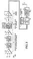
- the third embodiment of the invention illustrated in FIG. 3 is an effective compromise between the simplest embodiment described with reference to FIG. 1 and the very sophisticated digital embodiment described with reference to FIG. 2.
- the equipment comprises, as before, the set 1 of differential amplification and band filtering, the set 2 of 50 Hz rejection and its harmonics, the set 3 of amplification with automatic gain control, but at instead of sampling the analog signal to obtain a digitized signal which after processing modulates a carrier F p , the analog ECG signal is directly modulated by a channel coding circuit 10 by a pseudo-random code PN chosen between several orthogonal codes, to allow upon reception to distinguish the signal transmitted by this transmitter from an analog signal transmitted by a neighboring transmitter.
- PN pseudo-random code
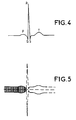
- FIG. 4 illustrates the ECG signal with its characteristic points PQRST and FIG. 5 illustrates the signal coded after channel coding by pseudo-random code.
- the cyclic code particular to the channel is repeated every millisecond, that is to say approximately 1000 times over the duration of the order of 1s of the ECG wave.
- the signal thus coded is directly applied to the modulator 11 of the carrier frequency F p .
- close links are differentiated by the codes assigned to each of them even if their carriers are identical (so-called "CDMA" technique).
- this version does not make it possible to introduce an error correcting coding, but nevertheless allows a weighting of the results obtained as a function of the correlation maximums.
- the corresponding reception station comprises means for reception, demodulation and, for the digital version, decoding, and restitution of the analog ECG signal which are classic.
- the corresponding reception station also includes the means for separating the necessary channels.
- the reception equipment is suitable.
- the signal is restored on reception by synchronization on the code, that is to say from a "sample” of signal at the frequency 1 KHz. Indeed, it is necessary to acquire the synchronization, that is to say to identify the instants when the expected code is present, by correlation with the code reference and to sub-sample the signal thus constructed by taking the samples successive corresponding to the successive maximums of the correlation signal: the restored signal is a signal at the rate of 1 KHz.
- FIG. 6 The block diagram of the receiver associated with the transmitter to form the system according to the invention is illustrated in FIG. 6 where the signals have also been illustrated at three points of the receiver: the signal received on the reception antenna 20 is the carrier modulated by the coded ECG signal. After demodulation and digitization of the quadrature channels I and Q in a demodulator 21 receiving the carrier frequency F p and corresponding to the modulator used in the transmitter, this signal is applied to an operator 22 which also receives the code assigned to the channel corresponding to the transmitter to be monitored by a code generator 23. A summer 24 on 256 elements, that is to say the code length, then makes it possible, in a maximum detector 25, to detect maximums which correspond to a synchronization between the channel code and successive signal samples at operator input. The envelope of these maximums obtained after subsampling by 256 in a circuit 26 is the ECG signal, PQRST restored.
- the carrier frequency was generated. It can be, conventionally from a carrier generator 15 located in the transmitter, as shown in dotted lines in FIG. 1. But, in another embodiment, the invention could use after processing the modulation signal a microwave transmission system in which the monitoring station S, for which the data produced in the equipment carried by the patient is intended, transmits to this equipment a microwave carrier wave interrogation F p , at 2.45 GHz for example.
- the equipment carried by the patient P1, P2 ... P4 comprises a card for modulating the wave received by the data to be transmitted before being returned to the station.
- the invention of a very broad field of application, is adaptable to the various targeted applications.
- a unidirectional link SIMPLEX point to point
- the information to be transmitted is the main electrode ECG signals (E1, E2, E3 / Reference). This information can be transmitted sequentially.
- the receiver is coupled to a plotter (analog or digital) and / or a recorder (analog or digital).
- Each patient / receiver link is selective and corresponds to a different examination room.
- the number of simultaneous connections required is at most of the order of 10.
- the examination time is on average 10 minutes, the desired autonomy is of the order of the day (recharging of the batteries is possible at night) . Comparable use can be found at the veterinarian for cardiological examinations of racehorses in particular.
- the information to be transmitted is the main electrode ECG signals (E1, E2, E3 / reference). This information can be transmitted sequentially.
- the central receiver is coupled to a plotter (analog or digital) and / or to a recorder (analog or digital).
- the short-range receiver corresponds to use in a room while the central (nodal) receiver allows monitoring of the patient regardless of his position in the clinic.
- Each patient / receptor link is selective.
- the number of simultaneous connections can become greater than 10.
- a bidirectional connection (DUPLEX) can also be implemented, the return then making it possible to transmit a voice or sound alarm (for order to put to rest, return to the room for examination. .). Otherwise an alarm mode of the "pager" type can be very useful.
- the applications described above are not limiting.
- the equipment according to the invention can also be used in sports halls.
Landscapes
- Health & Medical Sciences (AREA)
- Life Sciences & Earth Sciences (AREA)
- Engineering & Computer Science (AREA)
- Biomedical Technology (AREA)
- Medical Informatics (AREA)
- Computer Networks & Wireless Communication (AREA)
- Biophysics (AREA)
- Pathology (AREA)
- Physiology (AREA)
- Heart & Thoracic Surgery (AREA)
- Physics & Mathematics (AREA)
- Molecular Biology (AREA)
- Surgery (AREA)
- Animal Behavior & Ethology (AREA)
- General Health & Medical Sciences (AREA)
- Public Health (AREA)
- Veterinary Medicine (AREA)
- Measurement And Recording Of Electrical Phenomena And Electrical Characteristics Of The Living Body (AREA)
Applications Claiming Priority (2)
| Application Number | Priority Date | Filing Date | Title |
|---|---|---|---|
| FR9210568 | 1992-09-04 | ||
| FR9210568A FR2695503B1 (fr) | 1992-09-04 | 1992-09-04 | Système de transmission de données médicales, sans fil. |
Publications (2)
| Publication Number | Publication Date |
|---|---|
| EP0586286A1 true EP0586286A1 (de) | 1994-03-09 |
| EP0586286B1 EP0586286B1 (de) | 1997-07-02 |
Family
ID=9433213
Family Applications (1)
| Application Number | Title | Priority Date | Filing Date |
|---|---|---|---|
| EP93402090A Expired - Lifetime EP0586286B1 (de) | 1992-09-04 | 1993-08-24 | Drahtloses Übertragungssystem für medizinische Daten |
Country Status (4)
| Country | Link |
|---|---|
| US (1) | US5458122A (de) |
| EP (1) | EP0586286B1 (de) |
| DE (1) | DE69311860T2 (de) |
| FR (1) | FR2695503B1 (de) |
Cited By (2)
| Publication number | Priority date | Publication date | Assignee | Title |
|---|---|---|---|---|
| AT408146B (de) * | 1997-04-28 | 2001-09-25 | Vaillant Gmbh | Heizeinrichtung |
| FR2906050A1 (fr) * | 2006-09-20 | 2008-03-21 | Notocord Systems Soc Par Actio | Correction de signaux electrocardiographiques modifies par des filtres au sein de dispositifs de mesure |
Families Citing this family (55)
| Publication number | Priority date | Publication date | Assignee | Title |
|---|---|---|---|---|
| DE4329898A1 (de) | 1993-09-04 | 1995-04-06 | Marcus Dr Besson | Kabelloses medizinisches Diagnose- und Überwachungsgerät |
| US5573003A (en) * | 1995-01-27 | 1996-11-12 | Pacesetter, Inc. | Low-power delta modulator for intracardial signal monitoring in a cardiac device |
| US5756926A (en) * | 1995-04-03 | 1998-05-26 | Hughes Electronics | EFI detonator initiation system and method |
| IT1278679B1 (it) * | 1995-05-22 | 1997-11-27 | Paolo Alcidi | Metodo ed apparecchiatura per l'acquisizione ed il trattamento di segnali elettrocardiografici |
| USRE43128E1 (en) | 1995-07-28 | 2012-01-24 | Remote Access, Llc | Method for transmitting data packets on carrier frequency with linear variation and transmitter implementing this method |
| FR2738968B1 (fr) * | 1995-09-19 | 1997-10-24 | Thomson Csf | Procede de localisation d'un emetteur-recepteur de paquets de donnees et emetteur-recepteur mettant en oeuvre ce procede |
| US5767791A (en) * | 1995-11-13 | 1998-06-16 | Vitalcom | Low-power circuit and method for providing rapid frequency lock in a wireless communications device |
| US5944659A (en) | 1995-11-13 | 1999-08-31 | Vitalcom Inc. | Architecture for TDMA medical telemetry system |
| FR2750766B1 (fr) * | 1996-07-05 | 1998-11-13 | Thomson Csf | Procede d'analyse spectrale, notamment pour radioaltimetre de type fm/cw a traitement numerique |
| AUPQ088499A0 (en) * | 1999-06-10 | 1999-07-01 | Tentas Telehealth Pty Ltd | Acoustic transmission using digital mobile phones |
| KR100577410B1 (ko) * | 1999-11-30 | 2006-05-08 | 엘지.필립스 엘시디 주식회사 | 엑스레이 영상 감지소자 및 그 제조방법 |
| FR2803186B1 (fr) * | 2000-01-05 | 2002-08-09 | Guy Charvin | Procede et dispositif de recueil de potentiels evoques auditif |
| US6622050B2 (en) * | 2000-03-31 | 2003-09-16 | Medtronic, Inc. | Variable encryption scheme for data transfer between medical devices and related data management systems |
| US6458086B1 (en) | 2000-04-05 | 2002-10-01 | Kenneth Lawrence Franco | Implantable blood flow monitoring system |
| US6441747B1 (en) | 2000-04-18 | 2002-08-27 | Motorola, Inc. | Wireless system protocol for telemetry monitoring |
| US6496705B1 (en) | 2000-04-18 | 2002-12-17 | Motorola Inc. | Programmable wireless electrode system for medical monitoring |
| US6704592B1 (en) * | 2000-06-02 | 2004-03-09 | Medrad, Inc. | Communication systems for use with magnetic resonance imaging systems |
| US6662052B1 (en) | 2001-04-19 | 2003-12-09 | Nac Technologies Inc. | Method and system for neuromodulation therapy using external stimulator with wireless communication capabilites |
| US7197357B2 (en) | 2001-07-17 | 2007-03-27 | Life Sync Corporation | Wireless ECG system |
| US7933642B2 (en) | 2001-07-17 | 2011-04-26 | Rud Istvan | Wireless ECG system |
| US7091879B2 (en) * | 2002-02-05 | 2006-08-15 | Invivo Corporation | System and method for using multiple medical monitors |
| US7259906B1 (en) | 2002-09-03 | 2007-08-21 | Cheetah Omni, Llc | System and method for voice control of medical devices |
| US7294105B1 (en) | 2002-09-03 | 2007-11-13 | Cheetah Omni, Llc | System and method for a wireless medical communication system |
| US7065409B2 (en) | 2002-12-13 | 2006-06-20 | Cardiac Pacemakers, Inc. | Device communications of an implantable medical device and an external system |
| US7009511B2 (en) | 2002-12-17 | 2006-03-07 | Cardiac Pacemakers, Inc. | Repeater device for communications with an implantable medical device |
| US7395117B2 (en) | 2002-12-23 | 2008-07-01 | Cardiac Pacemakers, Inc. | Implantable medical device having long-term wireless capabilities |
| US7127300B2 (en) | 2002-12-23 | 2006-10-24 | Cardiac Pacemakers, Inc. | Method and apparatus for enabling data communication between an implantable medical device and a patient management system |
| US6978182B2 (en) | 2002-12-27 | 2005-12-20 | Cardiac Pacemakers, Inc. | Advanced patient management system including interrogator/transceiver unit |
| US7206625B2 (en) * | 2003-10-23 | 2007-04-17 | Vivosonic Inc. | Method and apparatus for the collection of physiological electrical potentials |
| EP1765165A2 (de) * | 2004-05-24 | 2007-03-28 | Equusys, Incorporated | Instrument für tiere |
| JP2008504025A (ja) * | 2004-06-21 | 2008-02-14 | イクエストロン エルエルシー | 動物の健康及び性能を評価するための方法及び装置 |
| US8150509B2 (en) | 2004-10-21 | 2012-04-03 | Cardiac Pacemakers, Inc. | Systems and methods for drug therapy enhancement using expected pharmacodynamic models |
| US7545272B2 (en) | 2005-02-08 | 2009-06-09 | Therasense, Inc. | RF tag on test strips, test strip vials and boxes |
| WO2006121530A2 (en) | 2005-04-01 | 2006-11-16 | Welch Allyn, Inc. | Vaginal speculum apparatus |
| DE102005015466A1 (de) * | 2005-04-04 | 2006-10-05 | Klaus Dipl.-Ing. Engel | Verfahren und Vorrichtung zur Aufzeichnung von Muskelaktivitäten bei Tieren mit Echtzeit-Kontrolle |
| US7752059B2 (en) | 2005-07-05 | 2010-07-06 | Cardiac Pacemakers, Inc. | Optimization of timing for data collection and analysis in advanced patient management system |
| US7595723B2 (en) | 2005-11-14 | 2009-09-29 | Edwards Lifesciences Corporation | Wireless communication protocol for a medical sensor system |
| MX2008015772A (es) * | 2006-07-18 | 2009-03-06 | Georgia Pacific Consumer Prod | Sistema de alimentacion de energia para surtidores y metodos para suministrar energia a surtidores. |
| CA2664846C (en) * | 2006-10-03 | 2014-12-23 | Georgia-Pacific Consumer Products Lp | Automated sheet product dispenser |
| US8214007B2 (en) | 2006-11-01 | 2012-07-03 | Welch Allyn, Inc. | Body worn physiological sensor device having a disposable electrode module |
| FI20075426A0 (fi) * | 2007-06-08 | 2007-06-08 | Polar Electro Oy | Suoritemittari, lähetysmenetelmä ja tietokoneohjelmatuote |
| US9700222B2 (en) | 2011-12-02 | 2017-07-11 | Lumiradx Uk Ltd | Health-monitor patch |
| US9734304B2 (en) | 2011-12-02 | 2017-08-15 | Lumiradx Uk Ltd | Versatile sensors with data fusion functionality |
| WO2014143276A2 (en) | 2012-12-31 | 2014-09-18 | Omni Medsci, Inc. | Short-wave infrared super-continuum lasers for natural gas leak detection, exploration, and other active remote sensing applications |
| US12484787B2 (en) | 2012-12-31 | 2025-12-02 | Omni Medsci, Inc. | Measurements using camera imaging tissue comprising skin or the hand |
| CA2895982A1 (en) | 2012-12-31 | 2014-07-03 | Omni Medsci, Inc. | Short-wave infrared super-continuum lasers for early detection of dental caries |
| US12502080B2 (en) | 2012-12-31 | 2025-12-23 | Omni Medsci, Inc. | Camera based wearable devices with artificial intelligence assistants |
| US9993159B2 (en) | 2012-12-31 | 2018-06-12 | Omni Medsci, Inc. | Near-infrared super-continuum lasers for early detection of breast and other cancers |
| US12193790B2 (en) | 2012-12-31 | 2025-01-14 | Omni Medsci, Inc. | Wearable devices comprising semiconductor diode light sources with improved signal-to-noise ratio |
| US10660526B2 (en) | 2012-12-31 | 2020-05-26 | Omni Medsci, Inc. | Near-infrared time-of-flight imaging using laser diodes with Bragg reflectors |
| US9500635B2 (en) | 2012-12-31 | 2016-11-22 | Omni Medsci, Inc. | Short-wave infrared super-continuum lasers for early detection of dental caries |
| WO2014105520A1 (en) | 2012-12-31 | 2014-07-03 | Omni Medsci, Inc. | Near-infrared lasers for non-invasive monitoring of glucose, ketones, hba1c, and other blood constituents |
| US8868164B2 (en) * | 2013-03-04 | 2014-10-21 | General Electric Company | Fetal monitoring device and method |
| US9532706B2 (en) | 2014-08-07 | 2017-01-03 | Welch Allyn, Inc. | Vaginal speculum with illuminator |
| EP3537959B1 (de) | 2016-11-11 | 2023-11-01 | 3M Innovative Properties Company | Systeme und verfahren zur drahtlosen überwachung des physiologischen zustandes |
Citations (6)
| Publication number | Priority date | Publication date | Assignee | Title |
|---|---|---|---|---|
| US3902478A (en) * | 1971-01-07 | 1975-09-02 | Francis Konopasek | Disaster alarm |
| EP0347515A1 (de) * | 1988-06-21 | 1989-12-27 | Belgian Electronic Research "B.E.R.", Societe Anonyme | Atemgeräuschanalysegerät |
| WO1990009143A1 (en) * | 1989-02-15 | 1990-08-23 | Jacob Segalowitz | Wireless electrocardiographic monitoring system |
| US4958645A (en) * | 1987-11-18 | 1990-09-25 | Cme Telemetrix Inc. | Multi-channel digital medical telemetry system |
| CH675675A5 (en) * | 1988-06-03 | 1990-10-31 | Ergonomics Ag | Transmission network for biological instrumentation signals - multiplexers outputs of channels and transmits via IR path |
| WO1991016851A1 (en) * | 1990-05-10 | 1991-11-14 | Stephen Margison | Heart beat monitoring |
Family Cites Families (3)
| Publication number | Priority date | Publication date | Assignee | Title |
|---|---|---|---|---|
| US3690313A (en) * | 1970-10-09 | 1972-09-12 | Mennen Greatbatch Electronics | Electrically isolated signal path means for a physiological monitor |
| US4478224A (en) * | 1982-11-26 | 1984-10-23 | Camino Laboratories, Inc. | Artifact detector for heartbeat rate measuring system |
| FI68734C (fi) * | 1983-11-11 | 1985-10-10 | Seppo Saeynaejaekangas | Foerfarande och anordning foer telemetrisk maetning av hjaertslag och ekg-signal med anvaendande av ett magnetiskt naerfaelt |
-
1992
- 1992-09-04 FR FR9210568A patent/FR2695503B1/fr not_active Expired - Fee Related
-
1993
- 1993-08-24 EP EP93402090A patent/EP0586286B1/de not_active Expired - Lifetime
- 1993-08-24 DE DE69311860T patent/DE69311860T2/de not_active Expired - Fee Related
- 1993-09-03 US US08/115,600 patent/US5458122A/en not_active Expired - Fee Related
Patent Citations (6)
| Publication number | Priority date | Publication date | Assignee | Title |
|---|---|---|---|---|
| US3902478A (en) * | 1971-01-07 | 1975-09-02 | Francis Konopasek | Disaster alarm |
| US4958645A (en) * | 1987-11-18 | 1990-09-25 | Cme Telemetrix Inc. | Multi-channel digital medical telemetry system |
| CH675675A5 (en) * | 1988-06-03 | 1990-10-31 | Ergonomics Ag | Transmission network for biological instrumentation signals - multiplexers outputs of channels and transmits via IR path |
| EP0347515A1 (de) * | 1988-06-21 | 1989-12-27 | Belgian Electronic Research "B.E.R.", Societe Anonyme | Atemgeräuschanalysegerät |
| WO1990009143A1 (en) * | 1989-02-15 | 1990-08-23 | Jacob Segalowitz | Wireless electrocardiographic monitoring system |
| WO1991016851A1 (en) * | 1990-05-10 | 1991-11-14 | Stephen Margison | Heart beat monitoring |
Cited By (3)
| Publication number | Priority date | Publication date | Assignee | Title |
|---|---|---|---|---|
| AT408146B (de) * | 1997-04-28 | 2001-09-25 | Vaillant Gmbh | Heizeinrichtung |
| FR2906050A1 (fr) * | 2006-09-20 | 2008-03-21 | Notocord Systems Soc Par Actio | Correction de signaux electrocardiographiques modifies par des filtres au sein de dispositifs de mesure |
| WO2008037876A3 (fr) * | 2006-09-20 | 2008-07-10 | Notocord Systems | Correction de signaux electrocardiographiques modifies par des filtres au sein de dispositifs de mesure |
Also Published As
| Publication number | Publication date |
|---|---|
| FR2695503B1 (fr) | 1994-10-21 |
| FR2695503A1 (fr) | 1994-03-11 |
| EP0586286B1 (de) | 1997-07-02 |
| DE69311860D1 (de) | 1997-08-07 |
| DE69311860T2 (de) | 1997-11-27 |
| US5458122A (en) | 1995-10-17 |
Similar Documents
| Publication | Publication Date | Title |
|---|---|---|
| EP0586286B1 (de) | Drahtloses Übertragungssystem für medizinische Daten | |
| US5279305A (en) | Electroencephalograph incorporating at least one wireless link | |
| US5415181A (en) | AM/FM multi-channel implantable/ingestible biomedical monitoring telemetry system | |
| EP0275781B1 (de) | Verfahren und Gerät zur Übertragung zu einem zentralen Registriergerät von seismischen Daten, welche von im Gelände verteilten Messgeräten ermittelt wurden | |
| KR100522132B1 (ko) | 인체통신시스템에서의 데이터 수신방법 및 수신장치 | |
| EP0250280B1 (de) | Anordnung für seismische Signaltransmission mittels Radiorelais | |
| US5503158A (en) | Ambulatory electrocardiogram monitor | |
| US20100303101A1 (en) | Real-time time encoding and decoding machines | |
| JPH05507835A (ja) | 干渉検出と特性化の方法及びその装置 | |
| FR2536881A1 (fr) | Machine a poker et recepteur portable a y utiliser | |
| FR2681997A1 (fr) | Procede et dispositif d'identification automatique d'un programme comportant un signal sonore. | |
| US4938229A (en) | Method and apparatus for transmitting data descriptive of electromagnetic waveform | |
| KR20030011785A (ko) | 멀티-채널 이시지 파형의 원거리통신 모니터링 방법 | |
| US5233999A (en) | Electromyograph with data transmission comprising no metallic conductors | |
| Thomas et al. | Rich-media tags: Battery-free wireless multichannel digital audio and image transmission with uhf rfid techniques | |
| EP2541782B1 (de) | RF-Telemetrie-Empfangsschaltkreis für aktives medizinisches Implantat | |
| JP2008521539A (ja) | 自律式生体内装置内における双方向通信 | |
| FR2670594A1 (fr) | Carte portative de reception de messages personnels. | |
| EP2649936B1 (de) | Datensynchronisationsverfahren und Datenübertragungssystem zur Durchführung des Verfahrens | |
| EP0097753B1 (de) | Tonempfänger für digitales Datenübertragungssystem | |
| FR2646301A1 (fr) | Appareil de communication a signal de bande de base a rapport signal/bruit eleve | |
| FR2727850A1 (fr) | Procede d'analyse a distance de parametres physiologiques ou de fonctionnement de dispositifs medicaux actifs, appareil autonome et equipement de site pour la mise en oeuvre de ce procede | |
| FR2627031A1 (fr) | Circuit et procede de demodulation | |
| JP2927262B2 (ja) | 医用テレメータ送信装置及び医用テレメータ装置 | |
| EP0959759A1 (de) | Multiplex-übertragungssystem für physiologische daten |
Legal Events
| Date | Code | Title | Description |
|---|---|---|---|
| PUAI | Public reference made under article 153(3) epc to a published international application that has entered the european phase |
Free format text: ORIGINAL CODE: 0009012 |
|
| AK | Designated contracting states |
Kind code of ref document: A1 Designated state(s): BE CH DE GB IT LI |
|
| 17P | Request for examination filed |
Effective date: 19940901 |
|
| 17Q | First examination report despatched |
Effective date: 19951016 |
|
| GRAG | Despatch of communication of intention to grant |
Free format text: ORIGINAL CODE: EPIDOS AGRA |
|
| GRAH | Despatch of communication of intention to grant a patent |
Free format text: ORIGINAL CODE: EPIDOS IGRA |
|
| GRAH | Despatch of communication of intention to grant a patent |
Free format text: ORIGINAL CODE: EPIDOS IGRA |
|
| GRAA | (expected) grant |
Free format text: ORIGINAL CODE: 0009210 |
|
| AK | Designated contracting states |
Kind code of ref document: B1 Designated state(s): BE CH DE GB IT LI |
|
| PG25 | Lapsed in a contracting state [announced via postgrant information from national office to epo] |
Ref country code: IT Free format text: LAPSE BECAUSE OF FAILURE TO SUBMIT A TRANSLATION OF THE DESCRIPTION OR TO PAY THE FEE WITHIN THE PRE;WARNING: LAPSES OF ITALIAN PATENTS WITH EFFECTIVE DATE BEFORE 2007 MAY HAVE OCCURRED AT ANY TIME BEFORE 2007. THE CORRECT EFFECTIVE DATE MAY BE DIFFERENT FROM THE ONE RECORDED.SCRIBED TIME-LIMIT Effective date: 19970702 |
|
| REG | Reference to a national code |
Ref country code: CH Ref legal event code: EP |
|
| REF | Corresponds to: |
Ref document number: 69311860 Country of ref document: DE Date of ref document: 19970807 |
|
| PG25 | Lapsed in a contracting state [announced via postgrant information from national office to epo] |
Ref country code: LI Free format text: LAPSE BECAUSE OF NON-PAYMENT OF DUE FEES Effective date: 19970831 Ref country code: CH Free format text: LAPSE BECAUSE OF NON-PAYMENT OF DUE FEES Effective date: 19970831 |
|
| GBT | Gb: translation of ep patent filed (gb section 77(6)(a)/1977) |
Effective date: 19970903 |
|
| REG | Reference to a national code |
Ref country code: CH Ref legal event code: PL |
|
| PLBE | No opposition filed within time limit |
Free format text: ORIGINAL CODE: 0009261 |
|
| STAA | Information on the status of an ep patent application or granted ep patent |
Free format text: STATUS: NO OPPOSITION FILED WITHIN TIME LIMIT |
|
| 26N | No opposition filed | ||
| PGFP | Annual fee paid to national office [announced via postgrant information from national office to epo] |
Ref country code: GB Payment date: 20000718 Year of fee payment: 8 |
|
| PGFP | Annual fee paid to national office [announced via postgrant information from national office to epo] |
Ref country code: DE Payment date: 20000719 Year of fee payment: 8 |
|
| PGFP | Annual fee paid to national office [announced via postgrant information from national office to epo] |
Ref country code: BE Payment date: 20000817 Year of fee payment: 8 |
|
| PG25 | Lapsed in a contracting state [announced via postgrant information from national office to epo] |
Ref country code: GB Free format text: LAPSE BECAUSE OF NON-PAYMENT OF DUE FEES Effective date: 20010824 |
|
| PG25 | Lapsed in a contracting state [announced via postgrant information from national office to epo] |
Ref country code: BE Free format text: LAPSE BECAUSE OF NON-PAYMENT OF DUE FEES Effective date: 20010831 |
|
| BERE | Be: lapsed |
Owner name: THOMSON-CSF Effective date: 20010831 |
|
| GBPC | Gb: european patent ceased through non-payment of renewal fee |
Effective date: 20010824 |
|
| PG25 | Lapsed in a contracting state [announced via postgrant information from national office to epo] |
Ref country code: DE Free format text: LAPSE BECAUSE OF NON-PAYMENT OF DUE FEES Effective date: 20020501 |