EP0586310A2 - Source rotative pour générer un champ magnétique à utiliser avec un détecteur de billets de banque - Google Patents
Source rotative pour générer un champ magnétique à utiliser avec un détecteur de billets de banque Download PDFInfo
- Publication number
- EP0586310A2 EP0586310A2 EP93420336A EP93420336A EP0586310A2 EP 0586310 A2 EP0586310 A2 EP 0586310A2 EP 93420336 A EP93420336 A EP 93420336A EP 93420336 A EP93420336 A EP 93420336A EP 0586310 A2 EP0586310 A2 EP 0586310A2
- Authority
- EP
- European Patent Office
- Prior art keywords
- dipoles
- magnetic field
- magnetic
- field source
- pair
- Prior art date
- Legal status (The legal status is an assumption and is not a legal conclusion. Google has not performed a legal analysis and makes no representation as to the accuracy of the status listed.)
- Granted
Links
Images
Classifications
-
- G—PHYSICS
- G07—CHECKING-DEVICES
- G07D—HANDLING OF COINS OR VALUABLE PAPERS, e.g. TESTING, SORTING BY DENOMINATIONS, COUNTING, DISPENSING, CHANGING OR DEPOSITING
- G07D7/00—Testing specially adapted to determine the identity or genuineness of valuable papers or for segregating those which are unacceptable, e.g. banknotes that are alien to a currency
- G07D7/04—Testing magnetic properties of the materials thereof, e.g. by detection of magnetic imprint
Definitions
- This invention relates to a magnetic field source for use in a currency detector, and more particularly to an alternating magnetic field source.
- a unique signature for a stack of currency may be deduced from the coercivity of the magnetic material comprising the magnetic ink. The detection of this unique signature necessitates measuring the hysteresis loop of the magnetic media of the currency. This measurement then allows the determination of the coercivity of the magnetic media.
- the invention in its simplest embodiment comprises a pair of identical permanent high energy magnet dipoles mounted on parallel rotatable shafts with their magnetic moments initially aligned in the same direction. As will be discussed below, additional magnetic dipoles can be added to increase the resultant magnetic field.
- the axes of magnetic dipoles lie in a plane perpendicular to the rotatable shafts, and the shafts are coupled to a drive motor for rotation in opposite directions. The magnetic dipoles give rise to a resultant field which is the sum of the fields due to the individual dipole magnetic moments.
- the field along that line has only a "longitudinal” component.
- “longitudinal” is defined as being along the direction of initial alignment, i.e., along the line connecting the center of the dipoles.
- the longitudinal components of each of the two dipoles add, being in the same direction, while the transverse (i.e. perpendicular to the longitudinal direction) components of the dipoles cancel, as they point in opposite directions.
- the longitudinal components still add, and the transverse components substantially, if not completely, cancel.
- the longitudinal components of the dipoles continue to add while the transverse components continue to subtract.
- the vector sum of the dipole fields is substantially a uniaxial sinusoidally varying magnetic field lying along the longitudinal direction.
- the preferred structure is configured for use in a hand held currency detector, and it will be appreciated that as the two magnet dipole assemblies and their associated drive elements are mechanically balanced and are counter rotating, there are no gyroscopic forces resulting from the inertia of the dipole assemblies to be overcome by the user manually sweeping the unit past the package or suitcase under inspection.
- the alternating uniaxial magnetic field generated by the dipoles is applied to the material under surveillance.
- the system detects and measures the magnetic hysteresis loop of the currency or other magnetic material being surveyed.
- the detector determines whether the detected hysteresis loop "matches" the known hysteresis loop of currency or the other material. A "match” indicates the presence of currency or other magnetic material being surveyed whereas the lack of a match indicates the absence of currency or other material under surveillance.
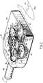
- Fig.1 is a drawing of an alternating magnetic field source according to the invention.
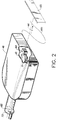
- Fig. 2 is a drawing of an alternating magnetic field source which contains magnetic field detectors in accordance with the invention.
- the preferred embodiment of the magnetic field source aspect of the invention utilizes two pairs of counter rotating magnetic dipole assemblies as shown in Fig. 1.
- Each magnetic assembly comprises a cylindrical disk of magnetic material 10,12,14,16 having rotatable axially positioned parallel shafts 24,26,28,30 perpendicular to the planes of the respective disks.
- the median planes of the disks 10,12,14,16 lie in a common plane, and the parallel shafts 24,26,28,30 are located at the corners of a quadrilateral in the common plane.
- the line in the common plane connecting the centers of the disks 10,12 defines the longitudinal direction, 44.
- Each disk fabricated from a magnetic material such as NdFeB, SmCo5, or BaFe magnetized in the plane of the disk so that the resultant field approximates that of a dipole.
- the rotation of the disks 10,12,14,16 are so phased that their magnetization vectors 18,20,22,25 are aligned and pointing in the longitudinal direction as shown in Fig. 1, once per revolution of the disks. It will be noted for this magnetization alignment that the longitudinal fields of the longitudinally positioned dipoles 10,12 add directly along the longitudinal direction whereas, for the indicated orientations of the magnetizations 22,25 of the off-axis dipoles 14,16, the fringing fields of the dipoles 14,16 add to the fields of the dipoles 10,12 along the longitudinal direction 44.
- the drive mechanism for the device is such that the shafts 24,26,28,30 are coupled for equal angular velocity rotation of the disks 10,12,14,16 with disks 12,14 rotating in one direction and disks 10,16 rotating in the opposite direction.
- the shafts 24,26,28,30 of the disks are coupled to drive shafts, 32,34,36,38 connected by couplings 40,42,43,45 mechanically driven by a battery, 56, energized motor and gearing 54, in a manner known in the art.
- a substantially longitudinal magnetic field, H(t) is generated by the rotating magnetic disks 10,12,14,16.
- One cycle of magnetic field H(t) occurs for each complete rotation of the disks 10,12,14,16, and the disk rotational speed is such that the magnetic field frequency is at least 5 Hz.
- a paddle-like container 46 having a handle 48 contains the components of the alternating field generator.
- the magnetic disks 10,12,14,16 and their associated drive elements, shafts 24,26,28,30, drive shafts 32,34,36,38 couplings 40,42,43,45 motor and gearing 54 and battery 56 are symmetrically positioned with respect to the centerline of the handle 48, which is also the longitudinal direction of the field H(t).
- the field H(t) is parallel to the major planar surface 50 of the paddle 46.
- the direction of the field H(t) sweeps out a path parallel to the moving surface 50.
- the uniaxial alternating magnetic field generated by the dipoles is applied to the material, 65, under surveillance.
- Two field detectors 62,64 such as Hall effect detectors, are mounted in the hand held unit as shown in Fig. 2 along the longitudinal direction of the field: one, 62, remotely positioned so that it responds only to the field generated by the rotating magnetic dipoles and the second, 64, positioned to respond both to the primary field generated by the dipoles and also to the induced field from the magnetic material 65 under inspection.
- each detector 62,64 are wired by dual wires 71,72 to buck each other so that the primary field contribution is cancelled, leaving the combined output of the detectors proportional to the field contribution of the magnetic material being surveyed.
- this combined output signal as well as a second signal sourced directly from the remotely-positioned detector can be used to derive the hysteresis loop of the material being surveyed.
- the induced signal from the surveyed material i.e., the combined signal
- the signal proportional to the field source itself i.e., the remotely-positioned signal
- This provides a visual display of the hysteresis loop of the inspected material. If this detected hysteresis loop "matches" the known hysteresis loop of currency or other magnetic material to be surveyed, then positive identification of currency or such other magnetic material can reasonably be inferred.
- An implementation of the invention weighed less than 15 lbs, and produced a field along the longitudinal axis of at least 50 Oe. at a distance of 4 inches from the surface 50 of the container 46.
Landscapes
- Physics & Mathematics (AREA)
- General Physics & Mathematics (AREA)
- Inspection Of Paper Currency And Valuable Securities (AREA)
- Geophysics And Detection Of Objects (AREA)
- Testing Of Coins (AREA)
Applications Claiming Priority (2)
| Application Number | Priority Date | Filing Date | Title |
|---|---|---|---|
| US932114 | 1992-08-19 | ||
| US07/932,114 US5315246A (en) | 1992-08-19 | 1992-08-19 | Rotating source for generating a magnetic field for use with a currency detector |
Publications (3)
| Publication Number | Publication Date |
|---|---|
| EP0586310A2 true EP0586310A2 (fr) | 1994-03-09 |
| EP0586310A3 EP0586310A3 (en) | 1996-05-29 |
| EP0586310B1 EP0586310B1 (fr) | 1998-10-28 |
Family
ID=25461791
Family Applications (1)
| Application Number | Title | Priority Date | Filing Date |
|---|---|---|---|
| EP93420336A Expired - Lifetime EP0586310B1 (fr) | 1992-08-19 | 1993-08-10 | Source rotative pour générer un champ magnétique à utiliser avec un détecteur de billets de banque |
Country Status (4)
| Country | Link |
|---|---|
| US (1) | US5315246A (fr) |
| EP (1) | EP0586310B1 (fr) |
| JP (1) | JPH06215221A (fr) |
| DE (1) | DE69321800T2 (fr) |
Cited By (2)
| Publication number | Priority date | Publication date | Assignee | Title |
|---|---|---|---|---|
| US6599535B2 (en) | 1995-07-14 | 2003-07-29 | Novartis Ag | Pharmaceutical compositions |
| US7173416B2 (en) | 2002-03-04 | 2007-02-06 | Sicpa Holding S.A. | Measurement probe and authentication device comprising the same |
Families Citing this family (1)
| Publication number | Priority date | Publication date | Assignee | Title |
|---|---|---|---|---|
| US5789916A (en) * | 1996-01-31 | 1998-08-04 | Axiohm Ipb Inc. | Method and apparatus for improving readhead performance |
Family Cites Families (12)
| Publication number | Priority date | Publication date | Assignee | Title |
|---|---|---|---|---|
| US2897438A (en) * | 1954-04-19 | 1959-07-28 | Well Surveys Inc | Casing joint detector |
| US3015063A (en) * | 1960-06-23 | 1961-12-26 | Camco Inc | Magnetic caliper |
| US3359495A (en) * | 1964-08-13 | 1967-12-19 | Bell Inc F W | Magnetic reaction testing apparatus and method of testing utilizing semiconductor means for magnetic field sensing of an eddy-current-reaction magnetic field |
| US4114804A (en) * | 1976-08-04 | 1978-09-19 | Brandt-Pra, Inc. | Counterfeit detection means for paper counting |
| US4066962A (en) * | 1976-12-08 | 1978-01-03 | The Singer Company | Metal detecting device with magnetically influenced Hall effect sensor |
| IL63137A0 (en) * | 1981-06-22 | 1982-07-30 | Nachshol Electronics Ltd | Apparatus for determining the authenticity of currency |
| CH662194A5 (de) * | 1984-02-14 | 1987-09-15 | Sodeco Compteurs De Geneve | Verfahren und einrichtung zum pruefen der echtheit von dokumenten. |
| US4668913A (en) * | 1985-03-14 | 1987-05-26 | International Business Machines Corporation | Constant flux magneto resistive magnetic reluctance sensing apparatus |
| US4764725A (en) * | 1986-09-12 | 1988-08-16 | Brandt, Inc. | Apparatus for detecting counterfeit currency using two coils to produce a saturating magnetic field |
| US4906988A (en) * | 1987-01-27 | 1990-03-06 | Rand Mcnally & Co. | Object verification system and method |
| US5068519A (en) * | 1990-01-10 | 1991-11-26 | Brandt, Inc. | Magnetic document validator employing remanence and saturation measurements |
| US5136239A (en) * | 1990-04-27 | 1992-08-04 | Josephs Richard M | Apparatus for measuring flux and other hysteretic properties in thin film recording discs |
-
1992
- 1992-08-19 US US07/932,114 patent/US5315246A/en not_active Expired - Lifetime
-
1993
- 1993-08-10 DE DE69321800T patent/DE69321800T2/de not_active Expired - Fee Related
- 1993-08-10 EP EP93420336A patent/EP0586310B1/fr not_active Expired - Lifetime
- 1993-08-16 JP JP5202427A patent/JPH06215221A/ja active Pending
Cited By (3)
| Publication number | Priority date | Publication date | Assignee | Title |
|---|---|---|---|---|
| US6599535B2 (en) | 1995-07-14 | 2003-07-29 | Novartis Ag | Pharmaceutical compositions |
| US6956043B2 (en) | 1995-07-14 | 2005-10-18 | Novartis Ag | Pharmaceutical compositions comprising 33-epi-chloro-33-desoxy-ascomycin solid dispersions |
| US7173416B2 (en) | 2002-03-04 | 2007-02-06 | Sicpa Holding S.A. | Measurement probe and authentication device comprising the same |
Also Published As
| Publication number | Publication date |
|---|---|
| EP0586310A3 (en) | 1996-05-29 |
| DE69321800D1 (de) | 1998-12-03 |
| US5315246A (en) | 1994-05-24 |
| DE69321800T2 (de) | 1999-05-20 |
| JPH06215221A (ja) | 1994-08-05 |
| EP0586310B1 (fr) | 1998-10-28 |
Similar Documents
| Publication | Publication Date | Title |
|---|---|---|
| US5705924A (en) | Hall effect sensor for detecting an induced image magnet in a smooth material | |
| Martín-Hernández et al. | A method for the separation of paramagnetic, ferrimagnetic and haematite magnetic subfabrics using high-field torque magnetometry | |
| EP3486628A1 (fr) | Système de mesure du couple et da la force | |
| EP0586310B1 (fr) | Source rotative pour générer un champ magnétique à utiliser avec un détecteur de billets de banque | |
| US4037149A (en) | Multiple mode magnetometers | |
| US4658658A (en) | Coil system for inductive measurement of the velocity of movement of a magnetized body | |
| JPH0933489A (ja) | Squid磁束計を用いた励磁コイル移動型渦電流探傷装置 | |
| Halverson et al. | Torque on a spinning hollow sphere in a uniform magnetic field | |
| US3178946A (en) | Rotating pendulum accelerometer | |
| US2907211A (en) | Gravity meter | |
| SU394654A1 (ru) | УСТРОЙСТВО дл ИЗМЕРЕНИЯ ТОЛЩИНЫ КРУПНОГАБАРИТНЫХ ИЗДЕЛИЙ | |
| US12105162B2 (en) | Multi-axis magnetic field vector generation | |
| Villalobos Jr | Transferring Power through a Magnetic Couple | |
| Zhu et al. | Temperature dependence for improving the accuracy of an electromagnetic microforce generating machine | |
| Birkfeld et al. | Calculation of the magnetic behaviour of electrical steel sheet under two dimensional excitation by means of the reluctance tensor | |
| Post et al. | Experimental Evidence for a Magnetic Monopole Field and Additional Test Results for Annual Variations in Field Magnitude | |
| RU2657465C1 (ru) | Способ обнаружения магнитного трения | |
| CN107561309A (zh) | 一种用于环境监测的在线风速检测装置 | |
| US3052410A (en) | Measuring apparatus | |
| US3260931A (en) | Diamagnetic gaussmeter | |
| RU2232399C2 (ru) | Магнитомеханический тесламетр | |
| CS65592A3 (en) | Apparatus for measuring clearance between rolls | |
| SU506754A1 (ru) | Устройство дл бесконтактного измерени угла наклона | |
| Kaczér et al. | A rotating probe for measuring the inhomogeneity of a magnetic field | |
| SE468705B (sv) | Foerfarande och anordning foer att medelst reluktansmetoden maeta avstaandet mellan tvaa varandra motstaaende ytor |
Legal Events
| Date | Code | Title | Description |
|---|---|---|---|
| PUAI | Public reference made under article 153(3) epc to a published international application that has entered the european phase |
Free format text: ORIGINAL CODE: 0009012 |
|
| AK | Designated contracting states |
Kind code of ref document: A2 Designated state(s): DE FR GB |
|
| PUAL | Search report despatched |
Free format text: ORIGINAL CODE: 0009013 |
|
| AK | Designated contracting states |
Kind code of ref document: A3 Designated state(s): DE FR GB |
|
| 17P | Request for examination filed |
Effective date: 19961109 |
|
| 17Q | First examination report despatched |
Effective date: 19970220 |
|
| GRAG | Despatch of communication of intention to grant |
Free format text: ORIGINAL CODE: EPIDOS AGRA |
|
| GRAG | Despatch of communication of intention to grant |
Free format text: ORIGINAL CODE: EPIDOS AGRA |
|
| GRAH | Despatch of communication of intention to grant a patent |
Free format text: ORIGINAL CODE: EPIDOS IGRA |
|
| GRAH | Despatch of communication of intention to grant a patent |
Free format text: ORIGINAL CODE: EPIDOS IGRA |
|
| GRAA | (expected) grant |
Free format text: ORIGINAL CODE: 0009210 |
|
| AK | Designated contracting states |
Kind code of ref document: B1 Designated state(s): DE FR GB |
|
| REF | Corresponds to: |
Ref document number: 69321800 Country of ref document: DE Date of ref document: 19981203 |
|
| ET | Fr: translation filed | ||
| PLBE | No opposition filed within time limit |
Free format text: ORIGINAL CODE: 0009261 |
|
| STAA | Information on the status of an ep patent application or granted ep patent |
Free format text: STATUS: NO OPPOSITION FILED WITHIN TIME LIMIT |
|
| 26N | No opposition filed | ||
| REG | Reference to a national code |
Ref country code: GB Ref legal event code: IF02 |
|
| PGFP | Annual fee paid to national office [announced via postgrant information from national office to epo] |
Ref country code: GB Payment date: 20060706 Year of fee payment: 14 |
|
| PGFP | Annual fee paid to national office [announced via postgrant information from national office to epo] |
Ref country code: FR Payment date: 20060803 Year of fee payment: 14 |
|
| PGFP | Annual fee paid to national office [announced via postgrant information from national office to epo] |
Ref country code: DE Payment date: 20060831 Year of fee payment: 14 |
|
| GBPC | Gb: european patent ceased through non-payment of renewal fee |
Effective date: 20070810 |
|
| REG | Reference to a national code |
Ref country code: FR Ref legal event code: ST Effective date: 20080430 |
|
| PG25 | Lapsed in a contracting state [announced via postgrant information from national office to epo] |
Ref country code: DE Free format text: LAPSE BECAUSE OF NON-PAYMENT OF DUE FEES Effective date: 20080301 |
|
| PG25 | Lapsed in a contracting state [announced via postgrant information from national office to epo] |
Ref country code: FR Free format text: LAPSE BECAUSE OF NON-PAYMENT OF DUE FEES Effective date: 20070831 |
|
| PG25 | Lapsed in a contracting state [announced via postgrant information from national office to epo] |
Ref country code: GB Free format text: LAPSE BECAUSE OF NON-PAYMENT OF DUE FEES Effective date: 20070810 |