EP0586538B1 - Distributeur de boissons convertible - Google Patents
Distributeur de boissons convertible Download PDFInfo
- Publication number
- EP0586538B1 EP0586538B1 EP92912482A EP92912482A EP0586538B1 EP 0586538 B1 EP0586538 B1 EP 0586538B1 EP 92912482 A EP92912482 A EP 92912482A EP 92912482 A EP92912482 A EP 92912482A EP 0586538 B1 EP0586538 B1 EP 0586538B1
- Authority
- EP
- European Patent Office
- Prior art keywords
- module
- dispense
- dispenser
- refrigeration
- dispense module
- Prior art date
- Legal status (The legal status is an assumption and is not a legal conclusion. Google has not performed a legal analysis and makes no representation as to the accuracy of the status listed.)
- Expired - Lifetime
Links
- 235000013361 beverage Nutrition 0.000 title claims abstract description 24
- 238000005057 refrigeration Methods 0.000 claims abstract description 85
- 239000006188 syrup Substances 0.000 claims abstract description 53
- 235000020357 syrup Nutrition 0.000 claims abstract description 53
- XLYOFNOQVPJJNP-UHFFFAOYSA-N water Substances O XLYOFNOQVPJJNP-UHFFFAOYSA-N 0.000 claims description 42
- 238000000034 method Methods 0.000 claims description 4
- 238000009434 installation Methods 0.000 abstract description 2
- 238000001816 cooling Methods 0.000 description 10
- 230000003134 recirculating effect Effects 0.000 description 10
- CDBYLPFSWZWCQE-UHFFFAOYSA-L Sodium Carbonate Chemical compound [Na+].[Na+].[O-]C([O-])=O CDBYLPFSWZWCQE-UHFFFAOYSA-L 0.000 description 9
- 238000006243 chemical reaction Methods 0.000 description 6
- 230000013011 mating Effects 0.000 description 3
- 230000008878 coupling Effects 0.000 description 2
- 238000010168 coupling process Methods 0.000 description 2
- 238000005859 coupling reaction Methods 0.000 description 2
- 238000010586 diagram Methods 0.000 description 2
- 235000020965 cold beverage Nutrition 0.000 description 1
- 230000008030 elimination Effects 0.000 description 1
- 238000003379 elimination reaction Methods 0.000 description 1
- 239000000796 flavoring agent Substances 0.000 description 1
- 235000019634 flavors Nutrition 0.000 description 1
- 239000005457 ice water Substances 0.000 description 1
- 239000007788 liquid Substances 0.000 description 1
- 238000004519 manufacturing process Methods 0.000 description 1
- 239000002184 metal Substances 0.000 description 1
- 238000012986 modification Methods 0.000 description 1
- 230000004048 modification Effects 0.000 description 1
- 239000004033 plastic Substances 0.000 description 1
- 238000005086 pumping Methods 0.000 description 1
- 239000002689 soil Substances 0.000 description 1
- 238000013517 stratification Methods 0.000 description 1
- 239000002023 wood Substances 0.000 description 1
Images






Classifications
-
- B—PERFORMING OPERATIONS; TRANSPORTING
- B67—OPENING, CLOSING OR CLEANING BOTTLES, JARS OR SIMILAR CONTAINERS; LIQUID HANDLING
- B67D—DISPENSING, DELIVERING OR TRANSFERRING LIQUIDS, NOT OTHERWISE PROVIDED FOR
- B67D1/00—Apparatus or devices for dispensing beverages on draught
- B67D1/0015—Apparatus or devices for dispensing beverages on draught the beverage being prepared by mixing at least two liquid components
- B67D1/0021—Apparatus or devices for dispensing beverages on draught the beverage being prepared by mixing at least two liquid components the components being mixed at the time of dispensing, i.e. post-mix dispensers
-
- B—PERFORMING OPERATIONS; TRANSPORTING
- B67—OPENING, CLOSING OR CLEANING BOTTLES, JARS OR SIMILAR CONTAINERS; LIQUID HANDLING
- B67D—DISPENSING, DELIVERING OR TRANSFERRING LIQUIDS, NOT OTHERWISE PROVIDED FOR
- B67D1/00—Apparatus or devices for dispensing beverages on draught
- B67D1/0015—Apparatus or devices for dispensing beverages on draught the beverage being prepared by mixing at least two liquid components
- B67D1/0021—Apparatus or devices for dispensing beverages on draught the beverage being prepared by mixing at least two liquid components the components being mixed at the time of dispensing, i.e. post-mix dispensers
- B67D1/0022—Apparatus or devices for dispensing beverages on draught the beverage being prepared by mixing at least two liquid components the components being mixed at the time of dispensing, i.e. post-mix dispensers the apparatus comprising means for automatically controlling the amount to be dispensed
- B67D1/0034—Apparatus or devices for dispensing beverages on draught the beverage being prepared by mixing at least two liquid components the components being mixed at the time of dispensing, i.e. post-mix dispensers the apparatus comprising means for automatically controlling the amount to be dispensed for controlling the amount of each component
-
- B—PERFORMING OPERATIONS; TRANSPORTING
- B67—OPENING, CLOSING OR CLEANING BOTTLES, JARS OR SIMILAR CONTAINERS; LIQUID HANDLING
- B67D—DISPENSING, DELIVERING OR TRANSFERRING LIQUIDS, NOT OTHERWISE PROVIDED FOR
- B67D1/00—Apparatus or devices for dispensing beverages on draught
- B67D1/0015—Apparatus or devices for dispensing beverages on draught the beverage being prepared by mixing at least two liquid components
- B67D1/0021—Apparatus or devices for dispensing beverages on draught the beverage being prepared by mixing at least two liquid components the components being mixed at the time of dispensing, i.e. post-mix dispensers
- B67D1/0022—Apparatus or devices for dispensing beverages on draught the beverage being prepared by mixing at least two liquid components the components being mixed at the time of dispensing, i.e. post-mix dispensers the apparatus comprising means for automatically controlling the amount to be dispensed
- B67D1/0034—Apparatus or devices for dispensing beverages on draught the beverage being prepared by mixing at least two liquid components the components being mixed at the time of dispensing, i.e. post-mix dispensers the apparatus comprising means for automatically controlling the amount to be dispensed for controlling the amount of each component
- B67D1/0035—Apparatus or devices for dispensing beverages on draught the beverage being prepared by mixing at least two liquid components the components being mixed at the time of dispensing, i.e. post-mix dispensers the apparatus comprising means for automatically controlling the amount to be dispensed for controlling the amount of each component the controls being based on the same metering technics
- B67D1/0037—Apparatus or devices for dispensing beverages on draught the beverage being prepared by mixing at least two liquid components the components being mixed at the time of dispensing, i.e. post-mix dispensers the apparatus comprising means for automatically controlling the amount to be dispensed for controlling the amount of each component the controls being based on the same metering technics based on volumetric dosing
-
- B—PERFORMING OPERATIONS; TRANSPORTING
- B67—OPENING, CLOSING OR CLEANING BOTTLES, JARS OR SIMILAR CONTAINERS; LIQUID HANDLING
- B67D—DISPENSING, DELIVERING OR TRANSFERRING LIQUIDS, NOT OTHERWISE PROVIDED FOR
- B67D1/00—Apparatus or devices for dispensing beverages on draught
- B67D1/0042—Details of specific parts of the dispensers
- B67D1/0043—Mixing devices for liquids
- B67D1/0044—Mixing devices for liquids for mixing inside the dispensing nozzle
- B67D1/0046—Mixing chambers
- B67D1/0049—Mixing chambers with means for diverging streams
-
- B—PERFORMING OPERATIONS; TRANSPORTING
- B67—OPENING, CLOSING OR CLEANING BOTTLES, JARS OR SIMILAR CONTAINERS; LIQUID HANDLING
- B67D—DISPENSING, DELIVERING OR TRANSFERRING LIQUIDS, NOT OTHERWISE PROVIDED FOR
- B67D1/00—Apparatus or devices for dispensing beverages on draught
- B67D1/0042—Details of specific parts of the dispensers
- B67D1/0057—Carbonators
- B67D1/006—Conventional carbonators
-
- B—PERFORMING OPERATIONS; TRANSPORTING
- B67—OPENING, CLOSING OR CLEANING BOTTLES, JARS OR SIMILAR CONTAINERS; LIQUID HANDLING
- B67D—DISPENSING, DELIVERING OR TRANSFERRING LIQUIDS, NOT OTHERWISE PROVIDED FOR
- B67D1/00—Apparatus or devices for dispensing beverages on draught
- B67D1/0042—Details of specific parts of the dispensers
- B67D1/0057—Carbonators
- B67D1/0069—Details
- B67D1/0074—Automatic carbonation control
-
- B—PERFORMING OPERATIONS; TRANSPORTING
- B67—OPENING, CLOSING OR CLEANING BOTTLES, JARS OR SIMILAR CONTAINERS; LIQUID HANDLING
- B67D—DISPENSING, DELIVERING OR TRANSFERRING LIQUIDS, NOT OTHERWISE PROVIDED FOR
- B67D1/00—Apparatus or devices for dispensing beverages on draught
- B67D1/06—Mountings or arrangements of dispensing apparatus in or on shop or bar counters
-
- B—PERFORMING OPERATIONS; TRANSPORTING
- B67—OPENING, CLOSING OR CLEANING BOTTLES, JARS OR SIMILAR CONTAINERS; LIQUID HANDLING
- B67D—DISPENSING, DELIVERING OR TRANSFERRING LIQUIDS, NOT OTHERWISE PROVIDED FOR
- B67D1/00—Apparatus or devices for dispensing beverages on draught
- B67D1/08—Details
- B67D1/0857—Cooling arrangements
- B67D1/0858—Cooling arrangements using compression systems
- B67D1/0861—Cooling arrangements using compression systems the evaporator acting through an intermediate heat transfer means
- B67D1/0864—Cooling arrangements using compression systems the evaporator acting through an intermediate heat transfer means in the form of a cooling bath
-
- B—PERFORMING OPERATIONS; TRANSPORTING
- B67—OPENING, CLOSING OR CLEANING BOTTLES, JARS OR SIMILAR CONTAINERS; LIQUID HANDLING
- B67D—DISPENSING, DELIVERING OR TRANSFERRING LIQUIDS, NOT OTHERWISE PROVIDED FOR
- B67D1/00—Apparatus or devices for dispensing beverages on draught
- B67D1/08—Details
- B67D1/12—Flow or pressure control devices or systems, e.g. valves, gas pressure control, level control in storage containers
- B67D1/1202—Flow control, e.g. for controlling total amount or mixture ratio of liquids to be dispensed
- B67D1/1204—Flow control, e.g. for controlling total amount or mixture ratio of liquids to be dispensed for ratio control purposes
- B67D1/1211—Flow rate sensor
-
- B—PERFORMING OPERATIONS; TRANSPORTING
- B67—OPENING, CLOSING OR CLEANING BOTTLES, JARS OR SIMILAR CONTAINERS; LIQUID HANDLING
- B67D—DISPENSING, DELIVERING OR TRANSFERRING LIQUIDS, NOT OTHERWISE PROVIDED FOR
- B67D1/00—Apparatus or devices for dispensing beverages on draught
- B67D1/08—Details
- B67D1/12—Flow or pressure control devices or systems, e.g. valves, gas pressure control, level control in storage containers
- B67D1/1277—Flow control valves
-
- B—PERFORMING OPERATIONS; TRANSPORTING
- B67—OPENING, CLOSING OR CLEANING BOTTLES, JARS OR SIMILAR CONTAINERS; LIQUID HANDLING
- B67D—DISPENSING, DELIVERING OR TRANSFERRING LIQUIDS, NOT OTHERWISE PROVIDED FOR
- B67D1/00—Apparatus or devices for dispensing beverages on draught
- B67D1/08—Details
- B67D1/12—Flow or pressure control devices or systems, e.g. valves, gas pressure control, level control in storage containers
- B67D1/1284—Ratio control
- B67D1/1295—Ratio defined by setting flow controllers
-
- F—MECHANICAL ENGINEERING; LIGHTING; HEATING; WEAPONS; BLASTING
- F25—REFRIGERATION OR COOLING; COMBINED HEATING AND REFRIGERATION SYSTEMS; HEAT PUMP SYSTEMS; MANUFACTURE OR STORAGE OF ICE; LIQUEFACTION SOLIDIFICATION OF GASES
- F25D—REFRIGERATORS; COLD ROOMS; ICE-BOXES; COOLING OR FREEZING APPARATUS NOT OTHERWISE PROVIDED FOR
- F25D23/00—General constructional features
- F25D23/003—General constructional features for cooling refrigerating machinery
-
- B—PERFORMING OPERATIONS; TRANSPORTING
- B67—OPENING, CLOSING OR CLEANING BOTTLES, JARS OR SIMILAR CONTAINERS; LIQUID HANDLING
- B67D—DISPENSING, DELIVERING OR TRANSFERRING LIQUIDS, NOT OTHERWISE PROVIDED FOR
- B67D2210/00—Indexing scheme relating to aspects and details of apparatus or devices for dispensing beverages on draught or for controlling flow of liquids under gravity from storage containers for dispensing purposes
- B67D2210/00028—Constructional details
- B67D2210/00031—Housing
- B67D2210/00034—Modules
-
- B—PERFORMING OPERATIONS; TRANSPORTING
- B67—OPENING, CLOSING OR CLEANING BOTTLES, JARS OR SIMILAR CONTAINERS; LIQUID HANDLING
- B67D—DISPENSING, DELIVERING OR TRANSFERRING LIQUIDS, NOT OTHERWISE PROVIDED FOR
- B67D2210/00—Indexing scheme relating to aspects and details of apparatus or devices for dispensing beverages on draught or for controlling flow of liquids under gravity from storage containers for dispensing purposes
- B67D2210/00028—Constructional details
- B67D2210/00031—Housing
- B67D2210/00039—Panels
-
- B—PERFORMING OPERATIONS; TRANSPORTING
- B67—OPENING, CLOSING OR CLEANING BOTTLES, JARS OR SIMILAR CONTAINERS; LIQUID HANDLING
- B67D—DISPENSING, DELIVERING OR TRANSFERRING LIQUIDS, NOT OTHERWISE PROVIDED FOR
- B67D2210/00—Indexing scheme relating to aspects and details of apparatus or devices for dispensing beverages on draught or for controlling flow of liquids under gravity from storage containers for dispensing purposes
- B67D2210/00028—Constructional details
- B67D2210/00047—Piping
-
- B—PERFORMING OPERATIONS; TRANSPORTING
- B67—OPENING, CLOSING OR CLEANING BOTTLES, JARS OR SIMILAR CONTAINERS; LIQUID HANDLING
- B67D—DISPENSING, DELIVERING OR TRANSFERRING LIQUIDS, NOT OTHERWISE PROVIDED FOR
- B67D2210/00—Indexing scheme relating to aspects and details of apparatus or devices for dispensing beverages on draught or for controlling flow of liquids under gravity from storage containers for dispensing purposes
- B67D2210/00028—Constructional details
- B67D2210/00099—Temperature control
- B67D2210/00104—Cooling only
-
- F—MECHANICAL ENGINEERING; LIGHTING; HEATING; WEAPONS; BLASTING
- F25—REFRIGERATION OR COOLING; COMBINED HEATING AND REFRIGERATION SYSTEMS; HEAT PUMP SYSTEMS; MANUFACTURE OR STORAGE OF ICE; LIQUEFACTION SOLIDIFICATION OF GASES
- F25D—REFRIGERATORS; COLD ROOMS; ICE-BOXES; COOLING OR FREEZING APPARATUS NOT OTHERWISE PROVIDED FOR
- F25D2400/00—General features of, or devices for refrigerators, cold rooms, ice-boxes, or for cooling or freezing apparatus not covered by any other subclass
- F25D2400/16—Convertible refrigerators
Definitions
- This invention relates to counter top, postmix beverage dispensers, and in particular to a low-cost, compact, versatile, multiflavor, convertible beverage dispenser.
- a wide variety of different postmix dispensers are known, including those having multiflavor valves and those having the selector buttons and nozzle at a notched corner of the cabinet. It is also known to having a dispensing system in which some parts of the dispenser are located above the counter and some parts are located below the counter.
- the present invention provides a method of arranging different elements of a convertible dispenser for dispensing beverages comprising: (a) providing a convertible beverage dispenser including a refrigeration module and a separate, built-in dispense module, said refrigeration module having a refrigeration module housing and said dispense module having a dispense module housing; (b) connecting a water line in said refrigeration module to a water line in said dispense module; (c) connecting a syrup line in said refrigeration module to a syrup line in said dispense module; (d) providing a selector button and a dispensing valve in said dispense module; (e) connecting said housings together when it is desired to operate said convertible dispenser as a one-piece countertop unit; (f) separating said housings from each other when it is desired to operate said dispenser as a two-piece unit and placing said refrigeration module below a countertop; (g) removing said selector button and dispensing valve from said dispense module and installing said button and valve in a second dispense module narrower than said built-
- a convertible multiflavor postmix beverage dispenser comprising: (a) a refrigeration module and a separate, built-in dispense module, said refrigeration module having a refrigeration module housing and said dispense module having a dispense module housing; (b) removable connecting means for connecting said housings together to operate as a one-piece unit and for separating said housings from each other such that said refrigeration module can be placed below a countertop for use with a countertop dispense module; (c) means for connecting a water line in said refrigeration module to a water line in said dispense module; (d) means for connecting a plurality of syrup lines in said refrigeration module to a plurality of syrup lines in said dispense module; (e) said refrigeration module including a refrigeration unit and a carbonation unit inside of said refrigeration module housing; (f) said dispense module including a plurality of selector buttons and a multiflavor dispensing valve with a dispensing nozzle for dispensing a beverage into a cup; (g) said
- the illustrated embodiments provide a low cost, compact, versatile, multiflavor, postmix, convertible beverage dispenser which can be oriented in any one of several different ways to fit into any available space in an outlet. If an outlet has room for a dispenser, this dispenser will fit. This advantage can be used to reduce the inventory of different sizes of dispensers presently needed to accommodate different outlets.
- This dispenser can be oriented frontways or sideways by an easy change in the location of the selector buttons.
- this unitary dispenser can be separated into a dispense module and a refrigeration module.
- the refrigeration module can be located below the counter and the dispense module can fit into a very small place on a counter.
- This convertible dispenser can be used with figals or can be used with bag-in-box with built-in syrup pumps. In addition, this convertible dispenser can be easily modified to dispense different numbers of beverages.
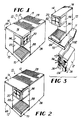
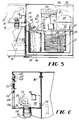
- Figs. 1-10 show one embodiment of the convertible beverage dispenser 10 of the present invention.
- the dispenser 10 includes a refrigeration module 12 and a separate dispense module 14 which is removably attached to the refrigeration module.
- the dispenser 10 has a single multiflavor valve 16 with a single mixing and dispensing nozzle 18 for dispensing a beverage into a cup 19 (Fig. 7), carbonated water line 22 and four syrup lines 24.
- the dispensing valve 16 is in a notched corner of the dispenser 10 with the buttons on either of the adjacent walls.
- the dispenser 10 as shown in the drawings is set up for use with bag-in-box syrup containers (not shown), although it can also be used with figals (not shown).
- the dispenser 10 can be set up for operation on a countertop 11 (see Fig. 3) in any one of the three modes of operation shown in Figs. 1, 2 or 3.
- a small conversion kit is used to convert from either the Fig. 1 or 2 mode to the Fig. 3 mode.
- the dispense module 14 is separated from the refrigeration module 12 and slightly rearranged (Fig. 7), the longer water and syrup lines are attached, a different splash plate (flat instead of L-shaped) is attached, and preferably a recirculating pump 134 and line are connected.
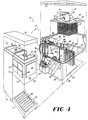
- the refrigeration module 12 includes a housing 26, a lid 28, an ice-water tank 30, a refrigeration unit 32, a carbonator unit 34, and four syrup pumps 36 mounted on the sidewall 38.
- the lid 28 has air inlet vents 13 in a front portion thereof and air outlet vents 15 in a rear portion thereof.
- the refrigeration unit 32 is mounted on a refrigeration deck 40 that sits on top of the tank 30.
- the unit 32 includes the usual equipment such as an evaporator coil 42, an agitator 44, condenser coils 46m compressor 48, ice bank control 50, and cooling fan 52 operated by an agitator motor 54,
- the carbonator unit 34 is mounted on a carbonator deck 56 and includes the usual carbonator equipment including a carbonator tank 58, a water pump and motor 60, level controller 62, and CO 2 inlet 64.
- the refrigeration module 12 also includes the usual water cooling coils 66 and four separate syrup cooling coils 68.
- the water goes to the pump 60, then to the water cooling soils 66, then to the carbonator tank 58 and then to the multiflavor valve 16.
- the syrup goes from a bag-in-box container (not shown) to one of the four syrup pumps 36, to a syrup cooling coil 68, and then to the multiflavor valve 16.
- Each pump 36 has a CO 2 inlet, a syrup inlet and a syrup outlet, for example, for a CO 2 operated pump.
- the dispense module 14 has a longer sidewall and shorter frontwall and includes a dispense module housing 69, a dispense section 70, a separate hollow section 72, and a lid 74.
- the hollow section 72 is generally U-shaped with an opening 76 in its rear wall 78 to accommodate the syrup pumps 36, in the modes of operation shown in Figs. 1 and 2.
- the hollow section 72 is attached by bolts and nuts 80 to the refrigeration module housing 26.
- the dispense section 70 includes separate upper and lower portions 82 and 84, respectively, and an L-shaped splash guard 88 in Figs. 1 and 2, and a flat splash guard 90 in Fig. 3.
- the lower portion is the drip tray unit and includes the drip tray 85 and the cup rest 86.
- the drip tray unit can be connected to the hollow section 72 and/or to the refrigeration module 12.
- the upper portion 82 includes a shell 92 having an open top 93 and an open rear wall 94.
- the shell 92 is bolted to both the refrigeration module housing 26 and to the hollow section 72 by bolts and nuts 80.
- the upper portion 82 includes the selector buttons 20, a panel 96, and the single multiflavor valve 16.
- the selector buttons 20 are placed in an opening 100 in a frontwall 98 of the dispense module 14, and the panel 96 is placed in an opening 102 in the sidewall 104.
- the selector buttons 20 are placed in the sidewall opening 102 and the panel 996 is placed in the frontwall opening 100.
- the selector buttons 20 are placed in the sidewall opening 102 as in Fig. 2.
- the openings 100 and 102 are identical in size and the buttons and panel can be handled through the open top 93 (with the lid 74 off).
- Each of the panel and buttons use connected to an identical mounting plate 106, so a description of one will suffice.
- the plate 106 has a flange 108 along its bottom edge that fits in a groove, and the plate has a single slot 105 centrally located in its top edge to receive a bolt 107 connected to the wall and on which a wing nut 109 is attached.
- the wires from the solenoids of the flow control modules 110 to the buttons 20 are flexible and easily allow movement of the buttons from one wall to the other.
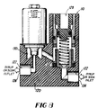
- the multiflavor valve 16 includes the single nozzle 18 and a plurality of separate, identical flow control modules 110, shown in Fig. 10.
- One of the flow control modules 110 is for carbonated water an there are four separate syrup modules 110, one for each of four syrups.
- a water line 112 extends from the water flow control module 110 to a central opening in the nozzle 18, while the four syrup lines 111, 112, 113, and 114 extend from a respective one of the flow control modules 110 to a respective one of the circumferentially arranged openings 116 in the top of the nozzle 18.
- each of the flow control modules 110 includes a body 120 and a liquid passageway 122 therethrough from an inlet port 124 to an outlet port 126.
- a standard piston-spring flow control 128 is located in the passage.
- a solenoid controlled valve 130 (including a solenoid, an armature, and a valve element movable onto and off of a valve seat) controls the on-off flow through the module 110.
- the dispenser 10 can be converted to a two-piece unit shown in Fig. 3 with only the very narrow dispense module placed on top of the countertop 11.
- This conversion from a one to two-piece unit can be easily done in the field with the aid of a small break-away conversion kit containing the long water and syrup lines 132, a recirculating water pump 134 to be mounted on the refrigerator module housing 26, and a flat splash plate 90.
- a small break-away conversion kit containing the long water and syrup lines 132, a recirculating water pump 134 to be mounted on the refrigerator module housing 26, and a flat splash plate 90.
- the lids are removed, the bolts and nuts 80 are removed, the recirculating water pump 134 is mounted on the housing 26, and the lines 132 are installed.
- the two sections 70 and 72 of the dispense unit are disconnected and then re-connected, using bolts and nuts 80 as shown in Fig. 10. In this way, the openings in their rear walls are facing each other and the dispense module has a smooth, clean, exterior surface.
- the drip tray is not connected to the shell 92, but its is connected to a drip tray support that is connected to the hollow section 72 and that extends under both sections 70 and 72 of the dispense module as shown in Figs. 1 and 2. This support is disconnected from the hollow section 70 and then reconnected to extend under the drip tray in Fig. 3.
- Fig. 9 shows the standard set up for the water line for the Figs. 1 and 2 modes of operation
- Fig. 10 shows the additional recirculating water line set up for the Fig. 3 mode of operation. This provides cold water for the dispenser at all times.
- Fig. 11 shows a dispense module 140 according to another embodiment similar to Fig. 3 except that the hollow section 72 is replaced (along with a different lid and drip tray support) with a different hollow section 142 having much less depth than does section 72.
- This embodiment would be used where only a very small countertop space is available.
- Fig. 12 shows another embodiment of this invention wherein the upper portion 82 of the dispense section 70 of the dispense module 14 is used by itself, by connecting it above a sink, such as under an existing cabinet (it can alternatively be wall mounted).
- Figs. 13-25 show a preferred embodiment of a convertible dispenser 210 of the present invention.
- the dispenser 210 is similar to the dispenser 10 described above with the following differences described below with reference to Figs. 13-25.
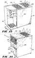
- Figs. 13 and 14 show the air vent arrangement of the dispenser 210.
- the dispenser 210 includes a lid 228 having air inlet vents 229 and air outlet vents 230 in a front portion and in a rear portion, respectively, of the lid 228.
- the refrigeration module 212 includes air inlet vents 233 in the upper portion of the sidewall 238.
- the refrigeration module 212 When the refrigeration module 212 is attached to the dispense module 214, air flows into the refrigeration module 212 through the air inlet vents 229, through the condenser 246, and out through the air outlet vents 230.
- the refrigeration module 212 may often be located in a confined space and the air flow could go directly from the air outlet vents 230 into the inlet vents 229. This would cause the compressor motor to run more often, wear out more quickly and could raise the drink temperature. Therefore, in this situation, the inlet vents 229 are covered by a plate 235 (of metal, wood or plastic, for example) and the air then flows in the air inlet vents 233 and out the air outlet vents 230. It has been found that this arrangement with the plate 235 avoids the problem mentioned above.
- Figs. 15 and 15A show the preferred arrangement of the refrigeration module 212 including a condenser 246 (or condenser coil), a cooling fan 252, a cooling fan motor 253, and a separate agitator motor 255.
- the fan and fan motor are mounted together as an integral, easily removable modular unit 257, including a bracket 259 which is held in place by two screws 261. This arrangement permits the use of a larger condenser than in the dispenser 10.
- the entire unit 257 can be easily slid out directly upwardly out of the dispenser 210 (after removing the lid 228).
- This also provides easy access to the agitator motor 255 and other components including a transformer mounted adjacent the motor 255.
- This feature is important because the dispenser 210 does not have a separate bonnet (or top half of the housing) as do many countertop dispensers, so access has to be through the top opening when the lid is removed.
- the dispenser 210 is small and compact, the internal components are easily accessible while the outside shell has a smooth, clean, and continuous surface providing a large advertising surface and a neat appearance.
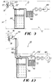
- Figs. 16 and 17 show the water and syrup circuits for the dispenser 210, both when the two modules are connected and when they are separated.
- Figs. 16 and 17 both show a cooling coil 271 in the soda line 273 downstream from the carbonator tank 258.
- the dispenser 210 also has the precooling coil 66 as shown in Figs. 9 and 10. This precooling coil 66 allows the use of a lower CO 2 pressure in the carbonator tank 258 and in fact the use of the same pressure in the tank 258 that is needed to operate the syrup pumps 36. This allows for the elimination of a separate CO 2 pressure regulator for the carbonator tank 258 and allows for the operation of the dispenser 210 with only the single CO 2 regulator 275 on the CO 2 cylinder 276.
- Fig. 17 shows a recirculating soda line 277, a pump 279 and a motor 281 for driving the pump, for use when the modules are separated. It is noted that this recirculating line is entirely downstream from the carbonator tank 258. This pumping can be controlled to turn on and off as desired but is preferably left on continuously. This recirculating soda line provides a cold drink at all times, even through the refrigeration module is located some distance away from the dispense module.
- Fig. 17 also shows a multiflavor nozzle 300, solenoid valves 285, flow controls 287, flow washers 289, a chilled water bath 291, the carbonator tank 258, the CO 2 cylinder 276, the pressure regulator 275, the syrup pumps 36, the carbonator pump 293, and the plain water line 295.
- Fig. 16 shows the same components except for the recirculating soda system which is not used when the dispense and refrigeration modules are connected.
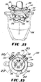
- Figs. 18-21 show the preferred nozzle 300 of the present invention used in the dispenser 210, including a nozzle body 302 and a spout 304.
- the nozzle body has a water passageway 306 therethrough and four separate syrup passages, one of which 308 is show in Fig. 20.
- the water goes straight down from a water inlet port 309 through an axial passage 310 in the nozzle body until it splits into two radial passages 312 and 314 at right angles to the axial passage 310.
- the passages 312 and 314 exit into an annular groove 316 from which the water hits the spout 304 and then flows down and out the spout opening 318.
- the four syrup passages are similar to each other and each start at a respective one of four separate syrup inlet ports 330, 331, 332 and 333 and continue through the nozzle body as described below for passage 308.
- the syrup passage 308 splits into two separate passages 320 and 322 and exit out two separated, spaced-apart, outlet openings 324 and 326 in a bottom wall 328 of the nozzle body 302.
- This nozzle provides improved mixing, less stratification in the beverage cup, and reduced flavor carryover. Any known method can be used to connect the spout to the nozzle such as a bayonet connection using two flanges on the spout.
- the hollow section 372 of the dispense module 214 referred to as the pump wrap because it covers the syrup pumps 36, can be easily removed to provide access to the syrup pumps by simply removing two screws 373 at the top thereof, and then lifting up to clear two pins from two holes at the lower end of the section 372.
- the same pin-hole arrangement is used to connect the drip tray unit 375 to the section 372 when the modules are separated.
- the pin-hole arrangement is shown in Fig. 25.
- the hollow section 372 has two holes 500 and 502 and the refrigeration module has two mating pins 504 and 506.
- the drip tray has two pins 508 and 510 and the refrigeration module has two mating holes 512 and 514. When the two modules are separated, the pins of the drip tray connect with the holes 500 and 502 in the hollow section 372.
- the dispenser 210 does not use the separate drip tray support of the dispenser 10 of Fig. 1. When the two modules are connected, there is preferably no connection between the two sections of the dispense module.
- the refrigeration module includes a recess 400 (see Fig. 15A) thereunder and a notch 402 in the sidewall 404 thereof to accommodate the CO 2 line, the water line and the syrup lines. All of these lines come up through the recess and then under the drip tray and into the hollow section.
- the drip tray unit 410 includes the drip tray 412 and the cup rest 414.
- the dispenser 210 can include legs, or not, as desired. If the refrigeration unit includes legs, then legs are also used on the dispense unit but preferably on the distal end thereof.
- Figs. 22-24 show certain connection details and the python 300.
- the long syrup and water lines 302 are preferably encased in a long insulated tube or python 300.
- Fig. 24 shows the end of the python connected to the refrigeration module 212 and Figs. 22 and 23 show the end connected to the dispense module 214.
- the python preferably extends through a hole 303 in the counter 304 on which the dispenser sits.
- Fig. 22 shows the fitting 306 for the recirculating soda line 277.
- a conduit 308 that goes into the multiflavor valve has a fitting 310 with an o-ring 312 and a groove 314.
- the end of a flexible line 316 includes a mating coupling 318 that slides over the fitting 310.
- a pin 320 slides through two holes 322 in the coupling 318 and into the groove 314 to hold the line to the conduit 308.
- the valve 110 is held to the wall 326 by sliding the conduit 308 down in the Keyway 328 to lock the wall 326 between the fitting 310 and the rear of the valve 110.
- the valve 110 is not shown in Fig. 23.
- the connections to the refrigeration module at the other end of the python are made the same way, as shown in Fig. 24.
- Fig. 24 also shows the return line and the pump 279 of the recirculating soda circuit.
- the pump 279 is mounted on the lower outside surface of the refrigeration module.
- the python extends up through the hollow section 72 of the dispense module 214.
- the electrical lines are in the cable 330.
- Figs. 25 and 26 show another embodiment of a convertible dispenser 600 of the present invention.
- the dispenser 600 is similar to the dispensers described above and in particular to the arrangement shown in Fig. 3 in which the narrow dispenser module 14 is on top of the countertop 11 and the refrigeration module 12 (or 212) is beneath the countertop.
- the same refrigeration module is used but a different dispense module 602 is used.
- the dispense module 602 is not part of ( i.e. , is not built-in) the complete dispenser 10 shown in the Fig. 1 arrangement, but includes some additional parts, and some of the parts of the dispenser 10 (or 210) are not used (and can be discarded).
- the dispense module 602 is set up the same as is the dispense module 14 (or 214).
- the dispense module 602 includes a dispensing head 604, a drip tray assembly 606 and a support 608, which elements are not taken from and are not part of the original dispenser 10 (or 210).
- the dispense module 602 housing includes the head 604, the drip tray 606 and the support 608.
- the selector buttons 20 and the single multiflavor valve 16 are used and are located in the dispensing head 604.
- the syrup and water lines are bundled together in a python 612 and the electrical line 614, which is wrapped around the python, are all located inside of the support 608.
- the dispense module 602 is smaller than the dispense module 14. It is smaller mainly in its width, that is, its side-to-side dimension; it is preferably also shorter in height and smaller in its front-to-back dimension.
- the dispensing head 602 is closer to the valve 16, that is, there is less gap between the valve 16 and the dispensing head.
- the individual flow control modules 110 can be rearranged, if desired, so as to take up less width.
- the dispense module 602 is preferably secured to the countertop either by screws 610 or by a C-clamp (not shown), and includes means for receiving and mounting therein the selector buttons and the dispensing valves, these means being identical to those for the dispense module 14 (or 214).
- the dispenser 600 would be set up similarly as in Fig. 3 except that the additional second dispense module 602 would be used in place of the existing dispense module 14.
- the dispensing head 604 preferably has a removable bottom to which the top and side walls attach after the buttons and valve are mounted in place.
- buttons can be located permanently in both places, with a cover over the ones not being used.
- the term "convertible” means a dispenser that can be converted in size and shape to fit in different available spaces.
- the hollow section 142 can be part of the dispense section with a hollow section like 72 left connected to the refrigeration module.
- the long lines can be stored in the hollow section 72. This would make the conversion easier and could avoid the need for a conversion kit.
- the dispense module can be made as a one-piece unit, and when separated from the refrigeration module, an additional, separate panel could be added to the open side that faces the refrigeration module when connected thereto.
- the refrigeration system is preferably mechanical although a cold plate could be used.
- the present invention provides a compact, multiflavor, low cost, versatile, convertible postmix beverage dispenser; a beverage dispenser that can be easily modified to dispense different numbers of beverages; an improved flow control module and method for easily changing the numbers of beverages to be dispensed; a dispenser with two fronts, which can be placed frontways or sideways, and having a small detachable dispense module which can be placed on top of a counter; a versatile dispenser that can be delivered to an outlet and that will fit in almost any available space; a single dispenser that is so versatile that it can be used to reduce the need for an inventory of dispensers of different sizes and shapes; a convertible dispenser having a vent arrangement that has one air-flow when the refrigeration and dispense modules are attached, and a different air flow when the modules are separated, for improved performance; a compact dispenser having a one-piece wrap-around shell, a removable lid, a vertically oriented condenser and a modular, easily removable condenser fan-motor
Landscapes
- Physics & Mathematics (AREA)
- Engineering & Computer Science (AREA)
- Thermal Sciences (AREA)
- Chemical & Material Sciences (AREA)
- Analytical Chemistry (AREA)
- Fluid Mechanics (AREA)
- Combustion & Propulsion (AREA)
- Mechanical Engineering (AREA)
- General Engineering & Computer Science (AREA)
- Devices For Dispensing Beverages (AREA)
Abstract
Claims (2)
- Procédé d'agencement des divers éléments d'un distributeur de boissons convertible consistant à :(a) fournir un distributeur de boissons convertible (10) comportant un module réfrigérant (12) et un autre module (14) distributeur intégré, ledit module réfrigérant (12) ayant un boítier (26) du module réfrigérant, et ledit module distributeur ayant un boítier (69) du module distributeur ;(b) relier une conduite d'eau dans ledit module réfrigérant (12) à une conduite d'eau dans ledit module distributeur (14) ;(c) relier une conduite de sirop dans ledit module réfrigérant (12) à une conduite de sirop dans ledit module distributeur (14) ;(d) fournir un bouton de sélection (20) et un robinet distributeur (18) dans ledit module distributeur (14) ;(e) relier ensemble lesdits boítiers (26, 69) quand on veut utiliser ledit distributeur convertible (10) comme une unité de comptoir d'un seul tenant(f) séparer lesdits boítiers (26, 69) l'un de l'autre quand on veut utiliser ledit distributeur (10) comme une unité en deux parties, et placer ledit module réfrigérant (12) sous un comptoir (11) ;(g) enlever lesdits bouton de sélection (20) et robinet distributeur (16) dudit module distributeur (14), et installer lesdits bouton (20) et robinet (16) dans un second module distributeur (602) plus étroit que ledit module distributeur intégré (14) ;(h) assujettir ledit second module distributeur (602) audit comptoir (11) ; et(i) relier ladite conduite d'eau et ladite conduite de sirop audit robinet distributeur (16).
- Distributeur de boissons après-mélange multiparfum convertible (10) comprenant :(a) un module réfrigérant (12) et un autre module (14) distributeur intégré, ledit module réfrigérant (12) ayant un boítier (26) du module réfrigérant, et ledit module distributeur ayant un boítier (69) du module distributeur ;(b) des moyens de connexion amovibles servant à relier ensemble lesdits boítiers (26, 69) pour le fonctionnement comme une unité d'un seul tenant, et à séparer lesdits boítiers l'un de l'autre pour pouvoir placer ledit module réfrigérant (12) sous un comptoir (11) afin de l'utiliser avec un module distributeur de comptoir ;(c) des moyens servant à relier une conduite d'eau dans ledit module réfrigérant (12) à une conduite d'eau dans ledit module distributeur (14)(d) des moyens servant à relier un ensemble de conduites de sirop dans ledit module réfrigérant (12) à un ensemble de conduites de sirop dans ledit module distributeur (14) ;(e) ledit module réfrigérant (12) comportant une unité réfrigérante (38) et un générateur de dioxyde de carbone (34) à l'intérieur dudit boítier (26) du module réfrigérant ;(f) ledit module distributeur (14) comportant un certain nombre de boutons de sélection (20) et un robinet distributeur de parfums multiples (16) muni d'un ajutage distributeur (18) servant à verser une boisson dans un gobelet ;(g) ledit module réfrigérant (12) étant plus grand que ledit module distributeur (14) et ledit boítier (26) du module réfrigérant ayant une largeur égale à la longueur dudit boítier (69) du module distributeur, et, quand lesdits boítiers sont reliés entre eux, une extrémité dudit boítier (26) du module réfrigérant étant reliée à un côté dudit boítier (69) du module distributeur ;(h) des moyens sur ladite extrémité dudit boítier (26) du module réfrigérant servant à monter un ensemble de pompes à sirop (36) sur sa face externe ;(i) ledit côté dudit boítier (69) du module distributeur comportant un orifice (76) pour pompes à sirop, et ledit boítier (69) du module distributeur comportant une partie évidée (78), adjacente audit orifice (76), suffisamment grande pour pouvoir y loger toute pompe à sirop (36) montée sur ledit module réfrigérant (12) ; et(j) un second module distributeur (602) plus étroit que ledit module distributeur intégré (14), des moyens servant à assujettir ledit module distributeur (602) à un comptoir (11), et des moyens servant à loger et à monter dans ledit module distributeur (602) lesdits boutons de sélection (20) et ledit robinet distributeur (16).
Applications Claiming Priority (3)
| Application Number | Priority Date | Filing Date | Title |
|---|---|---|---|
| US07/709,529 US5190188A (en) | 1987-12-04 | 1991-06-03 | Convertible beverage dispenser |
| US709529 | 1991-06-03 | ||
| PCT/US1992/004493 WO1992021607A1 (fr) | 1991-06-03 | 1992-06-03 | Distributeur de boissons convertible |
Publications (2)
| Publication Number | Publication Date |
|---|---|
| EP0586538A1 EP0586538A1 (fr) | 1994-03-16 |
| EP0586538B1 true EP0586538B1 (fr) | 1998-04-22 |
Family
ID=24850232
Family Applications (1)
| Application Number | Title | Priority Date | Filing Date |
|---|---|---|---|
| EP92912482A Expired - Lifetime EP0586538B1 (fr) | 1991-06-03 | 1992-06-03 | Distributeur de boissons convertible |
Country Status (9)
| Country | Link |
|---|---|
| US (1) | US5190188A (fr) |
| EP (1) | EP0586538B1 (fr) |
| JP (1) | JPH06508089A (fr) |
| AU (1) | AU657769B2 (fr) |
| DE (1) | DE69225223T2 (fr) |
| ES (1) | ES2114940T3 (fr) |
| FI (1) | FI935407A0 (fr) |
| NO (1) | NO934351L (fr) |
| WO (1) | WO1992021607A1 (fr) |
Cited By (1)
| Publication number | Priority date | Publication date | Assignee | Title |
|---|---|---|---|---|
| RU2732376C2 (ru) * | 2016-04-21 | 2020-09-16 | Пепсико, Инк. | Охлаждаемый пост-микс раздатчик |
Families Citing this family (50)
| Publication number | Priority date | Publication date | Assignee | Title |
|---|---|---|---|---|
| US5314091A (en) * | 1987-12-04 | 1994-05-24 | The Coca-Cola Company | Convertible beverage dispenser |
| US5368198A (en) * | 1992-08-26 | 1994-11-29 | Imi Cornelius Inc. | Beverage dispenser |
| US5433348A (en) | 1993-01-14 | 1995-07-18 | Lancer Corporation | Modular dispensing tower |
| USD358290S (en) | 1993-10-20 | 1995-05-16 | The Coca-Cola Company | Beverage dispensing tower |
| US5499744A (en) * | 1994-05-03 | 1996-03-19 | Lancer Corporation | Low profile drink dispenser |
| US5564601A (en) * | 1994-12-05 | 1996-10-15 | Cleland; Robert K. | Beverage dispensing machine with improved liquid chiller |
| USD373279S (en) | 1995-07-03 | 1996-09-03 | Bright Garden Industrial Co., Ltd. | Beverage dispenser |
| DE19911360A1 (de) * | 1999-03-15 | 2000-09-21 | Merck Patent Gmbh | Ausgabeeinrichtung für Flüssigkeiten |
| GB9910607D0 (en) * | 1999-05-08 | 1999-07-07 | Imi Cornelius Uk Ltd | Beverage dispenser |
| US6286720B1 (en) * | 1999-06-04 | 2001-09-11 | Lancer Partnership, Ltd. | Beverage dispenser with an improved cooling chamber configuration |
| EP1208058B1 (fr) | 1999-08-31 | 2004-10-27 | The Coca-Cola Company | Echangeur de chaleur pour distributeur de boissons |
| US6237810B1 (en) | 2000-03-29 | 2001-05-29 | The Coca-Cola Company | Modular beverage dispenser |
| US6234354B1 (en) | 2000-05-01 | 2001-05-22 | The Coca-Cola Company | Soft drink dispensing machine with modular customer interface unit |
| US6547100B2 (en) | 2000-05-01 | 2003-04-15 | The Coca-Cola Company | Soft drink dispensing machine with modular customer interface unit |
| US6708741B1 (en) | 2000-08-24 | 2004-03-23 | Ocean Spray Cranberries, Inc. | Beverage dispenser |
| EP1436226A4 (fr) | 2001-09-06 | 2008-07-16 | Manitowoc Foodservice Co Inc | Distributeur de boissons a faible volume |
| US7048147B2 (en) * | 2003-02-21 | 2006-05-23 | The Coca-Cola Company | Liquid dispensing device |
| US7086566B2 (en) * | 2003-07-03 | 2006-08-08 | Creamiser Products Corporation | Under counter dispenser |
| US7171993B2 (en) * | 2004-05-21 | 2007-02-06 | Pepsico, Inc. | Beverage dispenser with automatic cup-filling control |
| US7828175B2 (en) * | 2004-05-21 | 2010-11-09 | Pepsico, Inc. | Beverage dispensing system with a head capable of dispensing plural different beverages |
| US20070023443A1 (en) * | 2005-06-22 | 2007-02-01 | Anthony Huffman | Differentiated vending indicia and methods |
| US20080169308A1 (en) * | 2007-01-17 | 2008-07-17 | Martin Eugene M | Circulation system for delivering and dispensing bottled fluid |
| US8479954B2 (en) | 2008-05-15 | 2013-07-09 | Schroeder Industries, Inc. | System for identifying fluid pathways through a fluid carrying device |
| US9271604B2 (en) * | 2008-11-10 | 2016-03-01 | Automatic Bar Controls, Inc. | Manifold system for beverage dispenser |
| US9622615B2 (en) | 2008-11-10 | 2017-04-18 | Automatic Bar Controls, Inc. | Touch screen interface for a beverage dispensing machine |
| US20100187258A1 (en) * | 2009-01-27 | 2010-07-29 | Schroeder Industries, Inc. D/B/A Schroeder America | Post-mix dispenser assembly |
| GB2474741B (en) * | 2009-08-21 | 2012-03-07 | Schroeder Ind Inc | Beverage dispensing apparatus |
| US8944290B2 (en) * | 2009-10-12 | 2015-02-03 | Schroeder Industries, Inc. | Beverage dispensing system having a cold plate and recirculating pump |
| JP5788008B2 (ja) * | 2010-09-24 | 2015-09-30 | マニトワック・フードサービス・カンパニーズ・エルエルシー | リモート飲料システムに省エネルギーをもたらすシステムおよび方法 |
| CN102151086A (zh) * | 2011-03-04 | 2011-08-17 | 美的集团有限公司 | 一种带咖啡功能的饮水机 |
| WO2012130662A1 (fr) * | 2011-03-30 | 2012-10-04 | Nestec S.A. | Distributeur de boisson à ensemble buses amélioré |
| US8985396B2 (en) | 2011-05-26 | 2015-03-24 | Pepsico. Inc. | Modular dispensing system |
| US8746506B2 (en) * | 2011-05-26 | 2014-06-10 | Pepsico, Inc. | Multi-tower modular dispensing system |
| US10442671B2 (en) | 2011-08-29 | 2019-10-15 | Automatic Bar Controls, Inc. | Nozzle with isolation porting |
| KR102104539B1 (ko) * | 2013-02-28 | 2020-04-27 | 삼성전자주식회사 | 탄산수 제조 장치를 갖춘 냉장고 |
| ES2527362B2 (es) * | 2014-05-20 | 2015-06-11 | Esteban BANUS RICOMA | Sistema modular de dispensador de bebida |
| WO2016074711A1 (fr) * | 2014-11-12 | 2016-05-19 | Alfred Kärcher Gmbh & Co. Kg | Appareil de préparation de boissons |
| US10743563B2 (en) * | 2015-10-02 | 2020-08-18 | The Vollrath Company, L.L.C. | Frozen beverage dispenser |
| US9878892B2 (en) | 2016-02-05 | 2018-01-30 | Pepsico, Inc. | Vertical beverage dispensing manifolds, dispensers including the same, and methods of dispensing a beverage |
| UA124668C2 (uk) | 2016-02-12 | 2021-10-27 | Отометік Бар Контролз, Інк. | Розливна головка з ізольованими отворами |
| US10252900B2 (en) * | 2016-12-07 | 2019-04-09 | Cornelius Beverage Technologies Limited | Apparatuses, systems, and methods for dispensing beverages using alcoholic concentrates |
| JP7145856B2 (ja) * | 2016-12-14 | 2022-10-03 | ザ コカ・コーラ カンパニー | フレキシブル飲料分配システム |
| US10730735B2 (en) | 2018-09-24 | 2020-08-04 | Cornelius Beverage Technologies Limited | Alcoholic beverage dispensers with flow controls |
| US11479455B2 (en) | 2019-05-17 | 2022-10-25 | Pepsico, Inc. | Water dispensing station |
| DE102019128126A1 (de) * | 2019-10-17 | 2021-04-22 | Franke Kaffeemaschinen Ag | Kühlvorrichtung für Vorratsbehälter mit flüssigen Lebensmitteln |
| RU194994U1 (ru) * | 2019-11-06 | 2020-01-14 | Вячеслав Владимирович Вяткин | Корпус аквавендингового аппарата |
| WO2022046636A1 (fr) | 2020-08-24 | 2022-03-03 | Lancer Corporation | Soupape à cartouche et système |
| US11339045B2 (en) * | 2020-10-20 | 2022-05-24 | Elkay Manufacturing Company | Flavor and additive delivery systems and methods for beverage dispensers |
| US11912558B2 (en) | 2021-03-12 | 2024-02-27 | Smart Bar Usa Llc | Beverage dispense head assembly |
| USD991725S1 (en) * | 2021-04-29 | 2023-07-11 | Elkay Manufacturing Company | Beverage dispenser |
Family Cites Families (25)
| Publication number | Priority date | Publication date | Assignee | Title |
|---|---|---|---|---|
| US273654A (en) * | 1883-03-06 | Magazine fire-arm | ||
| US3261506A (en) * | 1964-10-07 | 1966-07-19 | Gold Bond Stamp Company | Beverage dispenser |
| US3327902A (en) * | 1965-10-22 | 1967-06-27 | Alterwitz Melvin | Chilled beverage dispensing system |
| US3355068A (en) * | 1965-10-24 | 1967-11-28 | Ametek Inc | Dispenser having means to pour main and supplemental quantities of liquids |
| US3331536A (en) * | 1966-05-20 | 1967-07-18 | Delfield Company | Drink dispenser |
| US3853244A (en) * | 1971-09-13 | 1974-12-10 | Reynolds Products | Remote drink dispenser |
| DE2308337A1 (de) * | 1972-03-20 | 1973-10-11 | Lykes Pasco Packing Co | Grossvolumige ausgabevorrichtung |
| US3863810A (en) * | 1973-10-09 | 1975-02-04 | Bar Mates Fluidic Systems Inc | Plural sources beverage dispensing apparatus |
| US3966091A (en) * | 1975-04-11 | 1976-06-29 | Eaton Corporation | Carbonated beverage dispenser having diffuser assembly |
| US4174872A (en) * | 1978-04-10 | 1979-11-20 | The Cornelius Company | Beverage dispensing machine and cabinet therefor |
| DE7930729U1 (de) * | 1979-10-30 | 1981-04-09 | Bosch-Siemens Hausgeräte GmbH, 7000 Stuttgart | Haushalt-getraenkeautomat |
| US4355735A (en) * | 1980-07-14 | 1982-10-26 | Tannetics, Inc. | Valving mechanism for beverage dispensing device |
| US4687120A (en) * | 1982-12-27 | 1987-08-18 | The Cornelius Company | Method and apparatus for dispensing cold beverage |
| GB2133086B (en) * | 1982-12-27 | 1987-01-14 | Cornelius Co | Method and apparatus for dispensing cold beverage |
| US4520960A (en) * | 1983-01-13 | 1985-06-04 | Halsey Taylor Division Of King-Seeley Thermos Co. | Barrier-free water cooler |
| US4577782A (en) * | 1983-05-02 | 1986-03-25 | The Cornelius Company | Beverage dispensing station |
| CA1202933A (fr) * | 1984-01-13 | 1986-04-08 | Gerald Doak | Traitement sanitaire pour debiteur de boissons |
| US4684039A (en) * | 1984-03-28 | 1987-08-04 | The Coca-Cola Company | Beverage dispenser valve assembly system for use with pulpy citrus concentrate |
| EP0165792A1 (fr) * | 1984-06-18 | 1985-12-27 | The Cornelius Company | Méthode et appareil pour refroidir et distribuer une boisson |
| US4836414A (en) * | 1986-05-02 | 1989-06-06 | The Coca-Cola Company | Premix dispensing system |
| US4781310A (en) * | 1986-12-19 | 1988-11-01 | The Coca-Cola Company | Beverage dispenser |
| IE62944B1 (en) * | 1987-12-04 | 1995-03-08 | Coca Cola Co | Convertible beverage dispenser |
| EP0339387A1 (fr) * | 1988-04-27 | 1989-11-02 | KKW Kulmbacher Klimageräte-Werk GmbH | Boîtier pour une machine frigorifique |
| GB2230252B (en) * | 1989-04-11 | 1992-10-14 | Objex Ltd | Multi-flavour drink dispenser |
| ZA913802B (en) * | 1990-05-22 | 1992-10-28 | Coca Cola Co | Convertible beverage dispenser |
-
1991
- 1991-06-03 US US07/709,529 patent/US5190188A/en not_active Expired - Fee Related
-
1992
- 1992-06-03 DE DE69225223T patent/DE69225223T2/de not_active Expired - Fee Related
- 1992-06-03 WO PCT/US1992/004493 patent/WO1992021607A1/fr not_active Ceased
- 1992-06-03 EP EP92912482A patent/EP0586538B1/fr not_active Expired - Lifetime
- 1992-06-03 FI FI935407A patent/FI935407A0/fi not_active Application Discontinuation
- 1992-06-03 AU AU20172/92A patent/AU657769B2/en not_active Ceased
- 1992-06-03 JP JP5500564A patent/JPH06508089A/ja active Pending
- 1992-06-03 ES ES92912482T patent/ES2114940T3/es not_active Expired - Lifetime
-
1993
- 1993-11-30 NO NO934351A patent/NO934351L/no unknown
Cited By (1)
| Publication number | Priority date | Publication date | Assignee | Title |
|---|---|---|---|---|
| RU2732376C2 (ru) * | 2016-04-21 | 2020-09-16 | Пепсико, Инк. | Охлаждаемый пост-микс раздатчик |
Also Published As
| Publication number | Publication date |
|---|---|
| WO1992021607A1 (fr) | 1992-12-10 |
| NO934351D0 (no) | 1993-11-30 |
| FI935407L (fi) | 1993-12-02 |
| US5190188A (en) | 1993-03-02 |
| FI935407A7 (fi) | 1993-12-02 |
| JPH06508089A (ja) | 1994-09-14 |
| AU657769B2 (en) | 1995-03-23 |
| ES2114940T3 (es) | 1998-06-16 |
| AU2017292A (en) | 1993-01-08 |
| FI935407A0 (fi) | 1993-12-02 |
| NO934351L (no) | 1994-02-01 |
| DE69225223T2 (de) | 1998-11-19 |
| EP0586538A1 (fr) | 1994-03-16 |
| DE69225223D1 (de) | 1998-05-28 |
Similar Documents
| Publication | Publication Date | Title |
|---|---|---|
| US5190188A (en) | Convertible beverage dispenser | |
| US5314091A (en) | Convertible beverage dispenser | |
| EP0676366B1 (fr) | Distributeur de boissons convertible | |
| AU699528B2 (en) | Cylindrical drink dispenser | |
| US8341975B2 (en) | Water dispenser | |
| US6698621B2 (en) | Selection manifold for beverage dispenser | |
| EP0711726B1 (fr) | Distributeur de boissons | |
| US4615466A (en) | Beverage dispenser system convertable between gravity and pressure | |
| KR20000076106A (ko) | 혼합 음료 디스펜서 | |
| US20140346189A1 (en) | Modular beverage dispenser having a built-in cold plate and carbonator | |
| CA1338247C (fr) | Distributeur de boissons transformable | |
| EP1268340B1 (fr) | Distributeur de boissons modulaire | |
| AU2001251732A1 (en) | Modular beverage dispenser | |
| US5556006A (en) | Drink supply apparatus | |
| GB2160502A (en) | Drink supply system for postmixed drinks | |
| HK1025940A (en) | Postmix beverage dispenser |
Legal Events
| Date | Code | Title | Description |
|---|---|---|---|
| PUAI | Public reference made under article 153(3) epc to a published international application that has entered the european phase |
Free format text: ORIGINAL CODE: 0009012 |
|
| 17P | Request for examination filed |
Effective date: 19931207 |
|
| AK | Designated contracting states |
Kind code of ref document: A1 Designated state(s): DE ES GB IT |
|
| 17Q | First examination report despatched |
Effective date: 19951011 |
|
| GRAG | Despatch of communication of intention to grant |
Free format text: ORIGINAL CODE: EPIDOS AGRA |
|
| GRAH | Despatch of communication of intention to grant a patent |
Free format text: ORIGINAL CODE: EPIDOS IGRA |
|
| GRAH | Despatch of communication of intention to grant a patent |
Free format text: ORIGINAL CODE: EPIDOS IGRA |
|
| GRAA | (expected) grant |
Free format text: ORIGINAL CODE: 0009210 |
|
| AK | Designated contracting states |
Kind code of ref document: B1 Designated state(s): DE ES GB IT |
|
| ITF | It: translation for a ep patent filed | ||
| REF | Corresponds to: |
Ref document number: 69225223 Country of ref document: DE Date of ref document: 19980528 |
|
| REG | Reference to a national code |
Ref country code: ES Ref legal event code: FG2A Ref document number: 2114940 Country of ref document: ES Kind code of ref document: T3 |
|
| PLBE | No opposition filed within time limit |
Free format text: ORIGINAL CODE: 0009261 |
|
| STAA | Information on the status of an ep patent application or granted ep patent |
Free format text: STATUS: NO OPPOSITION FILED WITHIN TIME LIMIT |
|
| 26N | No opposition filed | ||
| REG | Reference to a national code |
Ref country code: GB Ref legal event code: IF02 |
|
| PGFP | Annual fee paid to national office [announced via postgrant information from national office to epo] |
Ref country code: ES Payment date: 20030616 Year of fee payment: 12 |
|
| PGFP | Annual fee paid to national office [announced via postgrant information from national office to epo] |
Ref country code: GB Payment date: 20040528 Year of fee payment: 13 |
|
| PG25 | Lapsed in a contracting state [announced via postgrant information from national office to epo] |
Ref country code: ES Free format text: LAPSE BECAUSE OF NON-PAYMENT OF DUE FEES Effective date: 20040604 |
|
| PGFP | Annual fee paid to national office [announced via postgrant information from national office to epo] |
Ref country code: DE Payment date: 20040604 Year of fee payment: 13 |
|
| PG25 | Lapsed in a contracting state [announced via postgrant information from national office to epo] |
Ref country code: IT Free format text: LAPSE BECAUSE OF NON-PAYMENT OF DUE FEES Effective date: 20050603 Ref country code: GB Free format text: LAPSE BECAUSE OF NON-PAYMENT OF DUE FEES Effective date: 20050603 |
|
| REG | Reference to a national code |
Ref country code: ES Ref legal event code: FD2A Effective date: 20040604 |
|
| PG25 | Lapsed in a contracting state [announced via postgrant information from national office to epo] |
Ref country code: DE Free format text: LAPSE BECAUSE OF NON-PAYMENT OF DUE FEES Effective date: 20060103 |
|
| GBPC | Gb: european patent ceased through non-payment of renewal fee |
Effective date: 20050603 |