EP0586677B1 - Vorrichtung zur thermischen regelung einer umlaufenden flüssigkeit - Google Patents
Vorrichtung zur thermischen regelung einer umlaufenden flüssigkeit Download PDFInfo
- Publication number
- EP0586677B1 EP0586677B1 EP93907897A EP93907897A EP0586677B1 EP 0586677 B1 EP0586677 B1 EP 0586677B1 EP 93907897 A EP93907897 A EP 93907897A EP 93907897 A EP93907897 A EP 93907897A EP 0586677 B1 EP0586677 B1 EP 0586677B1
- Authority
- EP
- European Patent Office
- Prior art keywords
- plates
- fluid
- electrical
- heating
- heat
- Prior art date
- Legal status (The legal status is an assumption and is not a legal conclusion. Google has not performed a legal analysis and makes no representation as to the accuracy of the status listed.)
- Expired - Lifetime
Links
Images


Classifications
-
- F—MECHANICAL ENGINEERING; LIGHTING; HEATING; WEAPONS; BLASTING
- F24—HEATING; RANGES; VENTILATING
- F24H—FLUID HEATERS, e.g. WATER OR AIR HEATERS, HAVING HEAT-GENERATING MEANS, e.g. HEAT PUMPS, IN GENERAL
- F24H1/00—Water heaters, e.g. boilers, continuous-flow heaters or water-storage heaters
- F24H1/10—Continuous-flow heaters, i.e. heaters in which heat is generated only while the water is flowing, e.g. with direct contact of the water with the heating medium
- F24H1/12—Continuous-flow heaters, i.e. heaters in which heat is generated only while the water is flowing, e.g. with direct contact of the water with the heating medium in which the water is kept separate from the heating medium
- F24H1/121—Continuous-flow heaters, i.e. heaters in which heat is generated only while the water is flowing, e.g. with direct contact of the water with the heating medium in which the water is kept separate from the heating medium using electric energy supply
-
- F—MECHANICAL ENGINEERING; LIGHTING; HEATING; WEAPONS; BLASTING
- F28—HEAT EXCHANGE IN GENERAL
- F28F—DETAILS OF HEAT-EXCHANGE AND HEAT-TRANSFER APPARATUS, OF GENERAL APPLICATION
- F28F27/00—Control arrangements or safety devices specially adapted for heat-exchange or heat-transfer apparatus
-
- F—MECHANICAL ENGINEERING; LIGHTING; HEATING; WEAPONS; BLASTING
- F28—HEAT EXCHANGE IN GENERAL
- F28D—HEAT-EXCHANGE APPARATUS, NOT PROVIDED FOR IN ANOTHER SUBCLASS, IN WHICH THE HEAT-EXCHANGE MEDIA DO NOT COME INTO DIRECT CONTACT
- F28D21/00—Heat-exchange apparatus not covered by any of the groups F28D1/00 - F28D20/00
- F28D2021/0019—Other heat exchangers for particular applications; Heat exchange systems not otherwise provided for
- F28D2021/0077—Other heat exchangers for particular applications; Heat exchange systems not otherwise provided for for tempering, e.g. with cooling or heating circuits for temperature control of elements
Definitions
- the subject of the present invention is a device for thermal regulation of a circulating fluid used in particular for regulating the temperature of tools or reactors.
- Such devices intended to regulate the temperature of a tool for molding plastic materials by means of a heat transfer fluid circulating under the action of a pump already exist.
- the temperature of the fluid can be increased by means of electric heating resistances or decreased by means of a second cold fluid passing through an exchanger, the assembly being able to be controlled by means of an electronic regulator connected to one or more thermocouples judiciously arranged on the path of the heat transfer fluid and by various safety devices.
- these devices include a cooler heater for the heat transfer fluid formed by a reservoir inside which is disposed an electrical heating resistor and a cooling fluid circuit consisting of a coil, the electrical resistors of course being arranged at the inside a shielded tube, as described in document FR-A-2658332 (VULCANIC SA).
- control devices include a plate heat exchanger.
- a plate heat exchanger consisting of a stack of plates the fluid to be cooled and the cold fluid circulate in two different circuits without contact with each other, on either side of each plate.
- the regulating devices comprising such plate exchangers are bulky because the heating resistors must obviously be outside and quite spaced from said exchangers, hence a large volume of the assembly and the need to have a large amount of circulating heat transfer fluid.
- thermoregulation device allowing the passage of several fluids having to circulate vertically and alternately between the plates to open out at the top and at the bottom of the device while having a perfect seal.
- Patent DD-A-135,559 describes an installation allowing the heating and then the cooling of a liquid.
- This installation is more particularly intended to allow the pasteurization of the milk in which the milk must be brought to very high temperature then brought back to an ambient temperature for its packaging.
- This device is in the form of a plate exchanger system in which the fluid is first heated and then cooled.
- the system is therefore composed of three distinct elements mounted on a single support, namely two plate exchangers and an exchanger made up of hot plates.
- the fluid to be heated circulates between two heating plates.
- the fluid successively traverses the heating zone then the cooling zone. It is therefore not possible to obtain optimum temperature regulation of the circulating fluid.
- the object of the present invention is to remedy these drawbacks by producing a device for thermal regulation of a fluid consisting of a plurality of elementary assemblies each formed by a stack of ribbed and pleated plates defining by means of seals fluid circulation circuits, said plates being associated with electrical heating resistors.
- the walls of the electric heating element conform to the corrugated shape of the plates.
- the electrical resistance is embedded in a suitable material, for example ceramic or refractory cement, which is shaped identically to the ribbed plates so as to be inserted without difficulty between said plates.
- the heating element containing the electric heating resistors is filled with a conductive material such as in particular the aluminum in which the electric resistance is embedded.
- heating element is closed by means of a metal sleeve welded to the plates to ensure sealing around the orifice for the passage of fluids.
- the ribbed plates are welded around the fluid passage orifice and at their periphery.
- exchangers according to the invention advantageously makes it possible to produce devices for regulating the temperature of a mold or of a reactor, which are constituted by an exchanger according to the invention comprising plates with electrical heating resistance incorporated , crossed by a circuit of heat transfer fluids, forced circulation by a pump circulating from the exchanger to the tools in closed circuit without tank, and by a cooling circuit.
- the regulating device according to the invention is compact while having a large heat exchange surface and requires only a small volume of heat transfer fluid, generally water or oil. It also makes it possible to have a very short response time, the fluid being brought quickly to the desired temperature.
- the fluid thus regulated may in particular be a circuit of heat transfer liquid circulated by a pump and serving to regulate the temperature of tools or reactors, for example from 5 ° to 250 ° C.
- an exchanger comprising a stack of more or less large plates between which a greater or lesser number of heating plates are interposed.
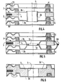
- Figures 4 & 5 are views, in partial section, of a stack of plates with a fluid circulation orifice.
- FIG. 1 is a block diagram of a basic element intended to constitute the temperature control device according to the invention, we see that it is formed of a stack 1 of corrugated or ribbed plates 2 of a type known for this application, for example made of stainless steel. These plates define by means of seals, not shown, but conventional circuits 11-13 alternating heat transfer fluids (FC) and refrigerants (FR).
- FC alternating heat transfer fluids
- FR refrigerants
- the electrically insulated electrical resistance (3) can be embedded in a filling conductive material such as aluminum, the walls of which conform to the corrugated shape of the usual plates, which advantageously makes it possible to remove them, resulting in substantial savings. .
- FIG 2 there is shown schematically a part of the plate stack 2 forming the exchanger of the device according to the invention.
- This exchanger is formed by the stacking of a number of plates 2 having in known manner scrolls, or corrugations 10 to force the circulating fluid to create turbulence; these plates 2 are provided with orifices 5 at each end to allow the entry and exit into their respective cavities of the heat transfer fluid (FC) and the coolant (FR). Between these plates 2 and on their periphery are arranged seals 6, of known type, which have the purpose of ensuring sealing between each plate 2 and also around the orifices 5 for inlet and outlet of the fluids of said stacked plates . So that the fluids can circulate between two plates 2, the seal 6 is sectioned around orifice 5 every second time, as seen in FIG. 2.
- a heating means 7 which may consist of one or more electrical resistances 3, arranged in a refractory material in the form of a plate 4, all of the resistors being connected to an electrical source, not shown.
- a seal 8 of circular section is placed around the orifice 5 where the fluid circulates.
- This seal 8 can have any cross section, but its thickness must be greater than the thickness of the heating plate 4 plus the distance separating two plates 2, so that during assembly it is crushed and thus ensures perfect sealing. It must also be made of material resistant to the maximum temperature envisaged.
- the cells 10 formed above and below the heating element 7 can be filled with refractory cement or an analogous material which is good conductor of heat.
- Above and below the stack of the exchanger plates are arranged two insulating plates, conventionally held by tie rods.
- Figure 3 there is shown a plan view of the plates 2 along line III-III of Figure 2, showing the orifices 5a for the passage of the coolant (FC) and those 5b of the coolant (FR) as well as the 'location of seals 8 and 6, the hatched central zone represents the location of the heating resistor 3. As can be seen, the active part of the heating elements is located below the seal 6.
- FIGS. 4 and 5 two alternative embodiments have been shown, showing the stack of plates 2 forming the exchanger of the device according to the invention, in which the seal 8 of the embodiment of FIG. 2 has been removed and replaced by a metal sleeve 20 welded to the plates 2b in order to ensure a perfect seal (fig. 4).
- the plates 2b have been shaped so that they can be welded at 61 around the opening 5 of the passage of the fluid 3 and at their periphery 60.
- FIG 6 there is shown another variant in which the electrical resistance 3 is embedded in a ceramic material 4, for example, insulating but good conductor of heat, which is shaped identically to the ribbed plates 2b so as to s 'insert without difficulty between said plates.
- An orifice 5 is provided for the passage of the fluid. This embodiment eliminates the seal 8.
- FIG. 7 is a diagram of the temperature control device according to the invention.
- the device according to the invention is very simple. It comprises a plate exchanger 1 with its electrical heating resistance (s) 3, crossed on the one hand, by a fluid circuit 11 coolant (FC) in forced circulation by means of a pump 12 to the mold of an injection molding machine or to the reactor of equipment, not shown, and on the other hand, by a cold water circuit 13.
- FC coolant
- the heat transfer fluid circulates from the plate exchanger 1 to the tooling in a closed circuit and without an intermediate storage tank.
- Three solenoid valves 14, 15 and 16 are provided to isolate the heat transfer fluid (FC) and limit leaks in the closed circuit 11 which goes to the mold or the reactor.
- a permanent temperature measurement in the exchanger linked to a known type of regulation system which allows a continuous reading of the temperature of the heat transfer fluid inside the exchanger and its limitation to a maximum temperature.
- This device can, if necessary, regulate the temperature if the mold or the reactor does not include a temperature probe.
- the device according to the present invention can be used not only for regulating the temperature of molds for injection molding machines but also for cylinders and extrusion screws, reactors used in the chemical industry and in addition for pumps. heat, solar or geothermal heating.
- the thermal regulation device according to the invention is of an advantageous cost price. Furthermore, it is easily removable since the various elements that constitute it can be quickly replaced or modified, it allows an ease of maintenance because we have access to the surfaces thus allowing their cleaning; moreover, it is compact and has a reduced response time.
Landscapes
- Engineering & Computer Science (AREA)
- Physics & Mathematics (AREA)
- Thermal Sciences (AREA)
- Mechanical Engineering (AREA)
- General Engineering & Computer Science (AREA)
- Chemical & Material Sciences (AREA)
- Combustion & Propulsion (AREA)
- Heat-Exchange Devices With Radiators And Conduit Assemblies (AREA)
- Central Heating Systems (AREA)
- Temperature-Responsive Valves (AREA)
- Instantaneous Water Boilers, Portable Hot-Water Supply Apparatuses, And Control Of Portable Hot-Water Supply Apparatuses (AREA)
- Steam Or Hot-Water Central Heating Systems (AREA)
Claims (8)
- Vorrichtung zum thermischen Regeln eines Fluids, bestehend aus einer Mehrzahl elementarer Baugruppen (1), von denen eine jede aus einem Stapel gerippter oder gefalteter Platten (2) gebildet ist, der mit Hilfe von Dichtungen Kreise für die Zirkulation des Fluids bildet, wobei die Platten elektrischen Heizwiderständen zugeordnet sind, dadurch gekennzeichnet,- daß jeder der Stapel gegenläufige Kreise (11,13) für ein Kühlfluid (FR) bzw. ein wärmeübertragendes Fluid (FC) definiert, und zwar unter Zwischenschaltung eines Heizelementes (7), das den elektrischen Heizwiderstand (3) enthält;- daß der Kreis für das wärmeübertragende Fluid (FC) in zwei parallele Unterkreise (FC1, FC2) unterteilt ist;- daß das Heizelement, das den elektrischen Heizwiderstand enthält, zwischen den beiden Unterkreisen (FC1, FC2) für das wärmeübertragende Fluid eingeschlossen ist; und- daß der Kreis für das Kühlfluid (FR) in zwei parallele Unterkreise (FR1, FR2) unterteilt ist, die die aus den Unterkreisen (FC1 und FC2) sowie dem den elektrischen Heizwiderstand enthaltenden Heizelement (7) gebildete Gesamtheit umschließen.
- Vorrichtung nach Anspruch 1, dadurch gekennzeichnet, daß die Wände des elektrischen Heizelementes (7) in ihrer Form an die gewellte Form der Platten (2) angepaßt sind.
- Vorrichtung nach Anspruch 2, dadurch gekennzeichnet, daß das die elektrischen Heizwiderstände enthaltende Heizelement (7) mit einem hitzebeständigen Zement von guter Wärmeleitfähigkeit ausgefüllt ist, in den der elektrische Widerstand eingegossen ist.
- Vorrichtung nach Anspruch 2, dadurch gekennzeichnet, daß das die elektrischen Heizwiderstände enthaltende Heizelement (7) mit einer keramischen Masse ausgefüllt ist, in die der elektrische Widerstand eingegossen ist.
- Vorrichtung nach Anspruch 2, dadurch gekennzeichnet, daß das die elektrischen Heizwiderstände enthaltende Heizelement (7) mit einem leitfähigen Werkstoff, beispielsweise Aluminium, ausgefüllt ist, , in den der elektrische Widerstand eingegossen ist.
- Vorrichtung nach einem der Ansprüche 1 bis 5, dadurch gekennzeichnet, daß das Heizelement (7) mittels einer metallischen Muffe (20) verschlossen ist, die an die Platten (2b) geschweißt ist, um die Dichtheit um die Öffnung (5) für den Durchtritt des Fluids herum zu gewährleisten.
- Vorrichtung nach einem der Ansprüche 1 bis 5, dadurch gekennzeichnet, daß die gerippten Platten (2b) um die Öffnung (5) für den Durchtritt des Fluids herum sowie an ihrem Umfang (60) geschweißt (61) sind.
- Vorrichtung zum Regeln der Temperatur einer Gießform oder eines Reaktors, dadurch gekennzeichnet, daß sie einen Wärmetauscher nach einem beliebigen der Ansprüche 1 bis 7 umfaßt, wobei der Wärmetauscher mit Platten (2) und darin integrierten elektrischen Heizwiderständen (3) versehen ist, und die Platten (2) von einem Kreis für ein wärmeübertragendes Fluid (FC) durchsetzt sind, das durch eine Pumpe (12) zwangsweise umgewälzt wird und von dem Wärmetauscher in einem geschlossenen Kreislauf ohne Reservoir zu einem Gerät sowie durch einen Kühlkreis (13) umläuft.
Applications Claiming Priority (3)
| Application Number | Priority Date | Filing Date | Title |
|---|---|---|---|
| FR9203701 | 1992-03-27 | ||
| FR9203701A FR2689227B1 (fr) | 1992-03-27 | 1992-03-27 | Dispositif de regulation thermique d'un fluide en circulation. |
| PCT/FR1993/000304 WO1993020389A1 (fr) | 1992-03-27 | 1993-03-26 | Dispositif de regulation thermique d'un fluide en circulation |
Publications (2)
| Publication Number | Publication Date |
|---|---|
| EP0586677A1 EP0586677A1 (de) | 1994-03-16 |
| EP0586677B1 true EP0586677B1 (de) | 1997-02-12 |
Family
ID=9428141
Family Applications (1)
| Application Number | Title | Priority Date | Filing Date |
|---|---|---|---|
| EP93907897A Expired - Lifetime EP0586677B1 (de) | 1992-03-27 | 1993-03-26 | Vorrichtung zur thermischen regelung einer umlaufenden flüssigkeit |
Country Status (7)
| Country | Link |
|---|---|
| EP (1) | EP0586677B1 (de) |
| AT (1) | ATE148939T1 (de) |
| CA (1) | CA2108796A1 (de) |
| DE (1) | DE69308090T2 (de) |
| ES (1) | ES2097498T3 (de) |
| FR (1) | FR2689227B1 (de) |
| WO (1) | WO1993020389A1 (de) |
Cited By (2)
| Publication number | Priority date | Publication date | Assignee | Title |
|---|---|---|---|---|
| US10451309B2 (en) | 2014-06-17 | 2019-10-22 | Alfa Laval Corporate Ab | Heater and a heat exchanger installation |
| WO2023180008A3 (de) * | 2022-03-22 | 2023-11-16 | Bayerische Motoren Werke Aktiengesellschaft | Temperiervorrichtung für ein elektrifiziertes kraftfahrzeug mit einer kühleinrichtung und einer heizeinrichtung |
Families Citing this family (7)
| Publication number | Priority date | Publication date | Assignee | Title |
|---|---|---|---|---|
| FR2712964B1 (fr) * | 1993-11-25 | 1995-12-29 | Vicard | Chaudière électrique pour liquide caloporteur en circulation dans un circuit ouvert ou fermé. |
| FR2775066B1 (fr) | 1998-02-18 | 2000-06-02 | Joel Bucaille | Plaque destinee a former un echangeur et procede d'utilisation |
| SE516844C3 (sv) * | 2000-07-07 | 2002-04-17 | Alfa Laval Ab | Plattvärme/plattvärmeväxlare med elektriskt uppvärmbara skikt i dubbelväggiga plattelement |
| DE102011003296A1 (de) * | 2011-01-28 | 2012-08-02 | Behr Gmbh & Co. Kg | Wärmeübertrager |
| FR3023364B1 (fr) * | 2014-07-03 | 2016-08-19 | Valeo Systemes Thermiques | Echangeur thermique a double circulation et installation de gestion thermique correspondante |
| DE102019213319A1 (de) * | 2019-09-03 | 2021-03-04 | Mahle International Gmbh | Wärmeübertrager |
| DE102024114058A1 (de) * | 2024-05-21 | 2025-11-27 | Sgl Carbon Se | Plattenwärmeübertrager |
Family Cites Families (12)
| Publication number | Priority date | Publication date | Assignee | Title |
|---|---|---|---|---|
| US1820458A (en) * | 1929-05-02 | 1931-08-25 | Jenkins Fredrick Alfred Edward | Electrical water heater |
| US2852232A (en) * | 1953-03-30 | 1958-09-16 | Gen Precision Lab Inc | Heat exchanger |
| GB1368271A (en) * | 1971-06-04 | 1974-09-25 | Nicolson T P | Electric heater for liquids and gases |
| FR2209918A1 (en) * | 1972-12-13 | 1974-07-05 | Ventes Lyonnaise Et | Temp. control of heat transfer fluids - especially for moulding tools for plastics or metal alloys |
| DE7730201U1 (de) * | 1977-09-29 | 1979-03-08 | Siemens Ag, 1000 Berlin Und 8000 Muenchen | Heizeinrichtung fuer durchlauferhitzer |
| DD135559A1 (de) * | 1978-03-10 | 1979-05-16 | Vnii Komplexnykh Mash Dlya Zhi | Pasteurisier-und kuehlanlage zum bearbeiten fluessiger produkte |
| DE3324901C2 (de) * | 1983-07-09 | 1986-02-20 | Hotset Heizpatronen und Zubehör GmbH, 5880 Lüdenscheid | Vorrichtung zur elektrischen Beheizung und zur Kühlung eines zentralen kunststofführenden Kanals einer Spritzgießmaschine |
| DE3344650A1 (de) * | 1983-08-08 | 1985-02-21 | Peter Dr.-Ing. 8000 München Vinz | Temperaturstabilisierte, isotherme prozesskammer mit automatischer prozesswaermeregelung |
| US4687907A (en) * | 1985-06-07 | 1987-08-18 | Pace, Incorporated | Heater device |
| HU196265B (en) * | 1986-04-11 | 1988-10-28 | Rolitron Mueszaki Fejlesztoe K | Method and apparatus for producing flow of wanted temperature of a physiological solution, as well as temperature control method and a heating device for the previously mentioned method and apparatus |
| FR2658332B1 (fr) * | 1990-02-09 | 1996-09-06 | Vulcanic Sa | Dispositif de regulation de temperature d'un outillage ou d'un reacteur au moyen d'un fluide caloporteur. |
| DE4016381A1 (de) * | 1990-05-21 | 1991-12-05 | Kaltenbach & Voigt | Elektrische heizvorrichtung zum erwaermen relativ kleiner mengen eines mediums oder mehrere medien, z.b. luft und wasser, insbesondere fuer zahnaerztliche zwecke |
-
1992
- 1992-03-27 FR FR9203701A patent/FR2689227B1/fr not_active Expired - Fee Related
-
1993
- 1993-03-26 WO PCT/FR1993/000304 patent/WO1993020389A1/fr not_active Ceased
- 1993-03-26 ES ES93907897T patent/ES2097498T3/es not_active Expired - Lifetime
- 1993-03-26 EP EP93907897A patent/EP0586677B1/de not_active Expired - Lifetime
- 1993-03-26 AT AT93907897T patent/ATE148939T1/de not_active IP Right Cessation
- 1993-03-26 DE DE69308090T patent/DE69308090T2/de not_active Expired - Fee Related
- 1993-03-26 CA CA002108796A patent/CA2108796A1/fr not_active Abandoned
Cited By (2)
| Publication number | Priority date | Publication date | Assignee | Title |
|---|---|---|---|---|
| US10451309B2 (en) | 2014-06-17 | 2019-10-22 | Alfa Laval Corporate Ab | Heater and a heat exchanger installation |
| WO2023180008A3 (de) * | 2022-03-22 | 2023-11-16 | Bayerische Motoren Werke Aktiengesellschaft | Temperiervorrichtung für ein elektrifiziertes kraftfahrzeug mit einer kühleinrichtung und einer heizeinrichtung |
Also Published As
| Publication number | Publication date |
|---|---|
| WO1993020389A1 (fr) | 1993-10-14 |
| FR2689227A1 (fr) | 1993-10-01 |
| ATE148939T1 (de) | 1997-02-15 |
| FR2689227B1 (fr) | 1999-05-14 |
| EP0586677A1 (de) | 1994-03-16 |
| DE69308090T2 (de) | 1997-05-28 |
| CA2108796A1 (fr) | 1993-09-28 |
| DE69308090D1 (de) | 1997-03-27 |
| ES2097498T3 (es) | 1997-04-01 |
Similar Documents
| Publication | Publication Date | Title |
|---|---|---|
| US5154661A (en) | Thermal electric cooling system and method | |
| US4726199A (en) | Superconducting apparatus | |
| AU605080B2 (en) | Thermoelectric cooling device | |
| FR2761203A1 (fr) | Dispositif de gestion de la temperature d'une batterie de generateurs electrochimiques | |
| EP0680585B1 (de) | Elektrischer kessel für wärmeträgerflüssigkeit in einem offenen oder geschlossenen kreislauf | |
| EP0627065A1 (de) | Wärmetauscherzusammenbau | |
| EP0153363A1 (de) | Wärmeaustauscher. | |
| EP0119502A1 (de) | Thermoelektrische Anlage | |
| FR2728666A1 (fr) | Echangeur de chaleur a trois fluides d'encombrement reduit | |
| EP0586677A1 (de) | Vorrichtung zur thermischen regelung einer umlaufenden flüssigkeit. | |
| US5606641A (en) | Device for thermal regulation of a circulating fluid comprising a stacked corrugated plate heat exchanger with heat transfer and cooling paths and electrical heating element therebetween | |
| FR3016479A1 (fr) | Plaque d'echange thermique pour gestion thermique de batterie et procede de fabrication associe | |
| FR2518243A1 (fr) | Refrigerant a huile du type a plaques | |
| FR2460464A1 (fr) | Echangeur de chaleur et tube utilise dans cet echangeur | |
| FR2481786A1 (fr) | Perfectionnements apportes aux installations thermo-electriques | |
| EP3172509B1 (de) | Vorrichtung zur kühlung einer trinkflüssigkeit, insbesondere trinkwasser, mit neuartigem kühlsystem mit peltier-effekt | |
| FR3026165A1 (fr) | Dispositif de traitement thermique d'un fluide a consommation energetique reduite | |
| FR2702829A1 (fr) | Installation thermo-électrique. | |
| WO1999067584A1 (en) | Heat exchanger tracking | |
| JP3542548B2 (ja) | 流体の温度調節装置 | |
| JP3641670B2 (ja) | 冷却器 | |
| FR2604846A1 (fr) | Generateur electrothermique a conduction directe | |
| WO2025002904A1 (fr) | Dispositif de refroidissement configure pour refroidir un module electronique | |
| AU759584B2 (en) | Storage box apparatus | |
| EP1593925B1 (de) | Plattenwärmetauscher |
Legal Events
| Date | Code | Title | Description |
|---|---|---|---|
| PUAI | Public reference made under article 153(3) epc to a published international application that has entered the european phase |
Free format text: ORIGINAL CODE: 0009012 |
|
| AK | Designated contracting states |
Kind code of ref document: A1 Designated state(s): AT BE CH DE ES FR GB IT LI NL SE |
|
| 17P | Request for examination filed |
Effective date: 19940616 |
|
| 17Q | First examination report despatched |
Effective date: 19950627 |
|
| GRAG | Despatch of communication of intention to grant |
Free format text: ORIGINAL CODE: EPIDOS AGRA |
|
| GRAH | Despatch of communication of intention to grant a patent |
Free format text: ORIGINAL CODE: EPIDOS IGRA |
|
| GRAH | Despatch of communication of intention to grant a patent |
Free format text: ORIGINAL CODE: EPIDOS IGRA |
|
| GRAA | (expected) grant |
Free format text: ORIGINAL CODE: 0009210 |
|
| AK | Designated contracting states |
Kind code of ref document: B1 Designated state(s): AT BE CH DE ES FR GB IT LI NL SE |
|
| REF | Corresponds to: |
Ref document number: 148939 Country of ref document: AT Date of ref document: 19970215 Kind code of ref document: T |
|
| REG | Reference to a national code |
Ref country code: CH Ref legal event code: NV Representative=s name: BUGNION S.A. Ref country code: CH Ref legal event code: EP |
|
| ITF | It: translation for a ep patent filed | ||
| GBT | Gb: translation of ep patent filed (gb section 77(6)(a)/1977) |
Effective date: 19970214 |
|
| REF | Corresponds to: |
Ref document number: 69308090 Country of ref document: DE Date of ref document: 19970327 |
|
| REG | Reference to a national code |
Ref country code: ES Ref legal event code: FG2A Ref document number: 2097498 Country of ref document: ES Kind code of ref document: T3 |
|
| PLBE | No opposition filed within time limit |
Free format text: ORIGINAL CODE: 0009261 |
|
| STAA | Information on the status of an ep patent application or granted ep patent |
Free format text: STATUS: NO OPPOSITION FILED WITHIN TIME LIMIT |
|
| 26N | No opposition filed | ||
| REG | Reference to a national code |
Ref country code: FR Ref legal event code: CL |
|
| REG | Reference to a national code |
Ref country code: GB Ref legal event code: IF02 |
|
| PGFP | Annual fee paid to national office [announced via postgrant information from national office to epo] |
Ref country code: NL Payment date: 20020218 Year of fee payment: 11 |
|
| PGFP | Annual fee paid to national office [announced via postgrant information from national office to epo] |
Ref country code: AT Payment date: 20030218 Year of fee payment: 11 |
|
| PGFP | Annual fee paid to national office [announced via postgrant information from national office to epo] |
Ref country code: ES Payment date: 20030314 Year of fee payment: 11 |
|
| PGFP | Annual fee paid to national office [announced via postgrant information from national office to epo] |
Ref country code: GB Payment date: 20030318 Year of fee payment: 11 |
|
| PGFP | Annual fee paid to national office [announced via postgrant information from national office to epo] |
Ref country code: BE Payment date: 20030328 Year of fee payment: 11 |
|
| PG25 | Lapsed in a contracting state [announced via postgrant information from national office to epo] |
Ref country code: GB Free format text: LAPSE BECAUSE OF NON-PAYMENT OF DUE FEES Effective date: 20040326 Ref country code: AT Free format text: LAPSE BECAUSE OF NON-PAYMENT OF DUE FEES Effective date: 20040326 |
|
| PG25 | Lapsed in a contracting state [announced via postgrant information from national office to epo] |
Ref country code: ES Free format text: LAPSE BECAUSE OF NON-PAYMENT OF DUE FEES Effective date: 20040327 |
|
| PG25 | Lapsed in a contracting state [announced via postgrant information from national office to epo] |
Ref country code: BE Free format text: LAPSE BECAUSE OF NON-PAYMENT OF DUE FEES Effective date: 20040331 |
|
| BERE | Be: lapsed |
Owner name: *BUCAILLE JOEL Effective date: 20040331 |
|
| PG25 | Lapsed in a contracting state [announced via postgrant information from national office to epo] |
Ref country code: NL Free format text: LAPSE BECAUSE OF NON-PAYMENT OF DUE FEES Effective date: 20041001 |
|
| GBPC | Gb: european patent ceased through non-payment of renewal fee |
Effective date: 20040326 |
|
| NLV4 | Nl: lapsed or anulled due to non-payment of the annual fee |
Effective date: 20041001 |
|
| REG | Reference to a national code |
Ref country code: ES Ref legal event code: FD2A Effective date: 20040327 |
|
| PGFP | Annual fee paid to national office [announced via postgrant information from national office to epo] |
Ref country code: SE Payment date: 20080326 Year of fee payment: 16 |
|
| PGFP | Annual fee paid to national office [announced via postgrant information from national office to epo] |
Ref country code: DE Payment date: 20080411 Year of fee payment: 16 Ref country code: CH Payment date: 20080415 Year of fee payment: 16 |
|
| PGFP | Annual fee paid to national office [announced via postgrant information from national office to epo] |
Ref country code: IT Payment date: 20080331 Year of fee payment: 16 |
|
| PGFP | Annual fee paid to national office [announced via postgrant information from national office to epo] |
Ref country code: FR Payment date: 20080331 Year of fee payment: 16 |
|
| REG | Reference to a national code |
Ref country code: CH Ref legal event code: PL |
|
| EUG | Se: european patent has lapsed | ||
| REG | Reference to a national code |
Ref country code: FR Ref legal event code: ST Effective date: 20091130 |
|
| PG25 | Lapsed in a contracting state [announced via postgrant information from national office to epo] |
Ref country code: LI Free format text: LAPSE BECAUSE OF NON-PAYMENT OF DUE FEES Effective date: 20090331 Ref country code: DE Free format text: LAPSE BECAUSE OF NON-PAYMENT OF DUE FEES Effective date: 20091001 Ref country code: CH Free format text: LAPSE BECAUSE OF NON-PAYMENT OF DUE FEES Effective date: 20090331 |
|
| PG25 | Lapsed in a contracting state [announced via postgrant information from national office to epo] |
Ref country code: FR Free format text: LAPSE BECAUSE OF NON-PAYMENT OF DUE FEES Effective date: 20091123 |
|
| PG25 | Lapsed in a contracting state [announced via postgrant information from national office to epo] |
Ref country code: IT Free format text: LAPSE BECAUSE OF NON-PAYMENT OF DUE FEES Effective date: 20090326 |
|
| PG25 | Lapsed in a contracting state [announced via postgrant information from national office to epo] |
Ref country code: SE Free format text: LAPSE BECAUSE OF NON-PAYMENT OF DUE FEES Effective date: 20090327 |