EP0586776A1 - Procédé de fabrication d'un roulement à double rangée de filles à contact oblique - Google Patents
Procédé de fabrication d'un roulement à double rangée de filles à contact oblique Download PDFInfo
- Publication number
- EP0586776A1 EP0586776A1 EP92850214A EP92850214A EP0586776A1 EP 0586776 A1 EP0586776 A1 EP 0586776A1 EP 92850214 A EP92850214 A EP 92850214A EP 92850214 A EP92850214 A EP 92850214A EP 0586776 A1 EP0586776 A1 EP 0586776A1
- Authority
- EP
- European Patent Office
- Prior art keywords
- race ring
- balls
- ring
- inner race
- unfinished
- Prior art date
- Legal status (The legal status is an assumption and is not a legal conclusion. Google has not performed a legal analysis and makes no representation as to the accuracy of the status listed.)
- Granted
Links
Images

Classifications
-
- F—MECHANICAL ENGINEERING; LIGHTING; HEATING; WEAPONS; BLASTING
- F16—ENGINEERING ELEMENTS AND UNITS; GENERAL MEASURES FOR PRODUCING AND MAINTAINING EFFECTIVE FUNCTIONING OF MACHINES OR INSTALLATIONS; THERMAL INSULATION IN GENERAL
- F16C—SHAFTS; FLEXIBLE SHAFTS; ELEMENTS OR CRANKSHAFT MECHANISMS; ROTARY BODIES OTHER THAN GEARING ELEMENTS; BEARINGS
- F16C19/00—Bearings with rolling contact, for exclusively rotary movement
- F16C19/02—Bearings with rolling contact, for exclusively rotary movement with bearing balls essentially of the same size in one or more circular rows
- F16C19/14—Bearings with rolling contact, for exclusively rotary movement with bearing balls essentially of the same size in one or more circular rows for both radial and axial load
- F16C19/18—Bearings with rolling contact, for exclusively rotary movement with bearing balls essentially of the same size in one or more circular rows for both radial and axial load with two or more rows of balls
- F16C19/181—Bearings with rolling contact, for exclusively rotary movement with bearing balls essentially of the same size in one or more circular rows for both radial and axial load with two or more rows of balls with angular contact
- F16C19/183—Bearings with rolling contact, for exclusively rotary movement with bearing balls essentially of the same size in one or more circular rows for both radial and axial load with two or more rows of balls with angular contact with two rows at opposite angles
- F16C19/184—Bearings with rolling contact, for exclusively rotary movement with bearing balls essentially of the same size in one or more circular rows for both radial and axial load with two or more rows of balls with angular contact with two rows at opposite angles in O-arrangement
-
- B—PERFORMING OPERATIONS; TRANSPORTING
- B23—MACHINE TOOLS; METAL-WORKING NOT OTHERWISE PROVIDED FOR
- B23P—METAL-WORKING NOT OTHERWISE PROVIDED FOR; COMBINED OPERATIONS; UNIVERSAL MACHINE TOOLS
- B23P15/00—Making specific metal objects by operations not covered by a single other subclass or a group in this subclass
- B23P15/003—Making specific metal objects by operations not covered by a single other subclass or a group in this subclass bearings
-
- F—MECHANICAL ENGINEERING; LIGHTING; HEATING; WEAPONS; BLASTING
- F16—ENGINEERING ELEMENTS AND UNITS; GENERAL MEASURES FOR PRODUCING AND MAINTAINING EFFECTIVE FUNCTIONING OF MACHINES OR INSTALLATIONS; THERMAL INSULATION IN GENERAL
- F16C—SHAFTS; FLEXIBLE SHAFTS; ELEMENTS OR CRANKSHAFT MECHANISMS; ROTARY BODIES OTHER THAN GEARING ELEMENTS; BEARINGS
- F16C33/00—Parts of bearings; Special methods for making bearings or parts thereof
- F16C33/30—Parts of ball or roller bearings
- F16C33/58—Raceways; Race rings
- F16C33/588—Races of sheet metal
-
- F—MECHANICAL ENGINEERING; LIGHTING; HEATING; WEAPONS; BLASTING
- F16—ENGINEERING ELEMENTS AND UNITS; GENERAL MEASURES FOR PRODUCING AND MAINTAINING EFFECTIVE FUNCTIONING OF MACHINES OR INSTALLATIONS; THERMAL INSULATION IN GENERAL
- F16C—SHAFTS; FLEXIBLE SHAFTS; ELEMENTS OR CRANKSHAFT MECHANISMS; ROTARY BODIES OTHER THAN GEARING ELEMENTS; BEARINGS
- F16C33/00—Parts of bearings; Special methods for making bearings or parts thereof
- F16C33/30—Parts of ball or roller bearings
- F16C33/58—Raceways; Race rings
- F16C33/64—Special methods of manufacture
Definitions
- the present invention refers to a method of manufacturing a double row angular contact ball bearing having an outer race ring and an inner race ring and a number of balls arranged between said outer and inner race rings in two axially spaced apart rows, said race rings being made from tubular sheet metal material.
- Ball bearings with race rings of sheet metal material are earlier known in various designs. Such bearings are simple and inexpensive and can be used in applications having not too high requirements for carrying capacity, speed and precision. Such bearings are usually manufactured in that the outer race ring and the inner race ring are shaped separately to final form by pressing or the like, whereupon the rings are assembled in common manner by insertion of balls therebetween. For manufacturing reasons such bearings earlier usually have been made as single row bearings, although there is also known double row bearings of this type. As shown in US-A-3,732,606, such older double row bearings often have had a split outer race ring, which facilitates the assembly of the bearing. DE-C-25 18 129 furthermore describes a double row angular contact ball bearing, wherein the race rings may be adjusted angularly relative to each other.
- EP-A2-0 328 496 describes double row angular contact ball bearings of this type and also some methods for manufacturing such inexpensive, simple and yet reliable bearings in a simple manner.
- One or both race rings in this publication is/are first shaped to finished or semi-finished state, e.g. by rolling, whereupon the inner ring is arranged coaxially inside the outer ring.
- the two rows of balls thereupon are inserted between the two rings and the unfinished and/or semi-finished ring is finally shaped by bending during rotation of the rings relative to each other for causing the rows of balls to roll constantly.
- the balls hereby will be permanently encapsulated in two rows, whereby the balls serve as the only counterholds during the shaping operation.
- the pressure applied on the portions to be bent shall be carefully adapted, but this makes it difficult to obtain the same desired play and preload in every bearing, due to small dimensional differences, etcetera.
- the purpose of the present invention is to provide a method, which in a simple and efficient manner solves this problem, and provides a possibility to obtain a predetermined and equal preload and play in every bearing manufactured, and which preload furthermore can be adjusted to the desired amount, and this has been obtained with a method incorporating the following steps:
- Fig.s 1 and 2 show schematically a double row, angular contact ball bearing having an inner race ring 11, an outer race ring 10 and two rows of balls 12 disposed between the race rings.
- the outer race ring 10 is provided with a circumferential depression 10a between the rows of balls, but is otherwise cylindrical.
- the inner race ring 11 is cylindrical but has circumferential, radially outwardly extending end portions 13 at its axial ends. The spaces formed by the circumferential depression 10a and the axial end portions 13 form together a raceway for each row of balls 12.
- the invention is not limited to such bearings but can be used also at bearings having a smaller number of retainer-guided balls.
- Fig. 3 illustrates schematically the first step in manufacturing a double row, angular contact ball bearing according to the present invention.
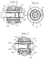
- a finished outer race ring 10 is inserted in a suitable manner axially into assembly position in the support of an assembly machine or the like, having clamping jaws 14 arranged to grip the outer race ring 10, when this is inserted therein and to hold it clamped with an adjustable clamping force.
- the jaws 14 are two semi-circular members, each having contact elements 14a, adapted to correspond to the curvature of the outer race ring and arranged to prevent the outer race ring from rotation, when the clamping jaws 14 are clamped about the outer race ring 10.
- contact elements 14a By suitable choice of material and size of the contact elements 14a and the size of the clamping force it is possible to determine in an accurate manner, when the outer race ring, thus clamped between the clamping jaws 14, shall begin to rotate, as the outer race ring is subjected to a torque.
- a tubular member 11 is inserted axially into the outer race ring 10 to a position concentrically aligned with the outer race ring 10. This is achieved with a first forming member, in the embodiment shown shaped as a mandrel 15 entering the tubular member 11.
- Balls 12 then are inserted in the annular space between the rings 10, 11 from both axial ends, as can be seen in Fig. 5.
- a second forming member, in this embodiment shaped as a further mandrel 16 is advanced from the side of the inner ring opposed to the one from which the first mandrel 15 is introduced in the inner ring, until this second mandrel 16 is in contact with the end face of the inner ring.
- the introduction of the balls 12 in the annular spaces can preferably by made with aid of a tool 17 schematically shown in Fig.s 5-7.
- each mandrel has an end portion 15a, 16a resp., of a diameter substantially corresponding to the internal diameter of the inner ring.
- Said end portion 15a of the first mandrel 15, which also serves to position the inner ring 11 concentrically in the outer ring 10, is rather long, whereas the opposite mandrel 16 can have a rather short end portion 16a.
- Both mandrels have an outer portion 15b, 16b resp. with diameter bigger than the internal diameter of the inner ring 11, the transitory portion 15c, 16c betweeen these two portions of different diameter being curved.
- the torque acting on the outer ring via the rotating balls thereby will overcome the clamping force, by which the contact elements 14a of the clamping members 14 hold the outer race ring, and hereby the outer race ring begins to rotate.
- This start of rotation is an indication that the desired preload in the bearing has been achieved and the force pressing the mandrels 15, 16 axially against the inner ring is relieved.
- the inner ring 11 then has been shaped to desired form where the rows of balls 12 are en-capsulated between the outer race ring 10 and the inner race ring 11.
- clamping jaws 14 which are shown in Fig. 6 as two semi-circular members, may of course be designed in other manners, and the exact design of the two forming members or mandrels 15, 16 may also differ from what is shown and described hereinbefore.
Landscapes
- Engineering & Computer Science (AREA)
- General Engineering & Computer Science (AREA)
- Mechanical Engineering (AREA)
- Manufacturing & Machinery (AREA)
- Support Of The Bearing (AREA)
- Rolling Contact Bearings (AREA)
- Mounting Of Bearings Or Others (AREA)
Priority Applications (3)
| Application Number | Priority Date | Filing Date | Title |
|---|---|---|---|
| DE1992606985 DE69206985T2 (de) | 1992-09-09 | 1992-09-09 | Verfahren zur Herstellung eines doppelreihigen Schrägkugellagers |
| EP19920850214 EP0586776B1 (fr) | 1992-09-09 | 1992-09-09 | Procédé de fabrication d'un roulement à double rangée de filles à contact oblique |
| ES92850214T ES2083143T3 (es) | 1992-09-09 | 1992-09-09 | Un metodo de fabricar un cojinete de bolas de contacto angular de doble fila. |
Applications Claiming Priority (1)
| Application Number | Priority Date | Filing Date | Title |
|---|---|---|---|
| EP19920850214 EP0586776B1 (fr) | 1992-09-09 | 1992-09-09 | Procédé de fabrication d'un roulement à double rangée de filles à contact oblique |
Publications (2)
| Publication Number | Publication Date |
|---|---|
| EP0586776A1 true EP0586776A1 (fr) | 1994-03-16 |
| EP0586776B1 EP0586776B1 (fr) | 1995-12-20 |
Family
ID=8212232
Family Applications (1)
| Application Number | Title | Priority Date | Filing Date |
|---|---|---|---|
| EP19920850214 Expired - Lifetime EP0586776B1 (fr) | 1992-09-09 | 1992-09-09 | Procédé de fabrication d'un roulement à double rangée de filles à contact oblique |
Country Status (3)
| Country | Link |
|---|---|
| EP (1) | EP0586776B1 (fr) |
| DE (1) | DE69206985T2 (fr) |
| ES (1) | ES2083143T3 (fr) |
Cited By (3)
| Publication number | Priority date | Publication date | Assignee | Title |
|---|---|---|---|---|
| GB2340894A (en) * | 1998-08-27 | 2000-03-01 | Nsk Rhp Europe Technology Co Ltd | A bearing assembly for use with water pumps |
| CN110331475A (zh) * | 2019-07-11 | 2019-10-15 | 经纬智能纺织机械有限公司 | 一种细纱机升降机构中的链滑轮托脚组合装置 |
| CN117620627A (zh) * | 2024-01-26 | 2024-03-01 | 无锡沃尔德轴承有限公司 | 一种圆柱滚子轴承的生产工艺 |
Families Citing this family (1)
| Publication number | Priority date | Publication date | Assignee | Title |
|---|---|---|---|---|
| WO2014182307A1 (fr) | 2013-05-10 | 2014-11-13 | Roller Bearing Company Of America, Inc. | Roulement préchargé à deux rangées de billes avec billes d'espacement |
Citations (5)
| Publication number | Priority date | Publication date | Assignee | Title |
|---|---|---|---|---|
| DE821887C (de) * | 1948-12-24 | 1951-11-22 | Werner Roterberg | Mehrreihiges Kugellager |
| GB1027274A (en) * | 1963-04-05 | 1966-04-27 | Geo H Hughes Ltd | Improvements relating to bearings |
| US3300261A (en) * | 1964-03-03 | 1967-01-24 | Torrington Co | Full complement roller radial thrust bearing |
| FR1600856A (fr) * | 1968-08-08 | 1970-08-03 | ||
| EP0328496A2 (fr) * | 1988-02-11 | 1989-08-16 | SKF Nova AB | Procédé de fabrication d'un palier axial-radial à double rangée de billes |
-
1992
- 1992-09-09 DE DE1992606985 patent/DE69206985T2/de not_active Expired - Fee Related
- 1992-09-09 ES ES92850214T patent/ES2083143T3/es not_active Expired - Lifetime
- 1992-09-09 EP EP19920850214 patent/EP0586776B1/fr not_active Expired - Lifetime
Patent Citations (5)
| Publication number | Priority date | Publication date | Assignee | Title |
|---|---|---|---|---|
| DE821887C (de) * | 1948-12-24 | 1951-11-22 | Werner Roterberg | Mehrreihiges Kugellager |
| GB1027274A (en) * | 1963-04-05 | 1966-04-27 | Geo H Hughes Ltd | Improvements relating to bearings |
| US3300261A (en) * | 1964-03-03 | 1967-01-24 | Torrington Co | Full complement roller radial thrust bearing |
| FR1600856A (fr) * | 1968-08-08 | 1970-08-03 | ||
| EP0328496A2 (fr) * | 1988-02-11 | 1989-08-16 | SKF Nova AB | Procédé de fabrication d'un palier axial-radial à double rangée de billes |
Cited By (7)
| Publication number | Priority date | Publication date | Assignee | Title |
|---|---|---|---|---|
| GB2340894A (en) * | 1998-08-27 | 2000-03-01 | Nsk Rhp Europe Technology Co Ltd | A bearing assembly for use with water pumps |
| FR2782759A1 (fr) * | 1998-08-27 | 2000-03-03 | Nsk Rhp Europe Technology Co Ltd | Ensemble de paliers pour pompe a eau |
| US6168316B1 (en) | 1998-08-27 | 2001-01-02 | Nsk-Rhp European Technology Co., Limited | Bearing assembly for use with water pumps |
| GB2340894B (en) * | 1998-08-27 | 2002-05-15 | Nsk Rhp Europe Technology Co Ltd | A bearing assembly for use with water pumps |
| CN110331475A (zh) * | 2019-07-11 | 2019-10-15 | 经纬智能纺织机械有限公司 | 一种细纱机升降机构中的链滑轮托脚组合装置 |
| CN117620627A (zh) * | 2024-01-26 | 2024-03-01 | 无锡沃尔德轴承有限公司 | 一种圆柱滚子轴承的生产工艺 |
| CN117620627B (zh) * | 2024-01-26 | 2024-04-30 | 无锡沃尔德轴承有限公司 | 一种圆柱滚子轴承的生产工艺 |
Also Published As
| Publication number | Publication date |
|---|---|
| ES2083143T3 (es) | 1996-04-01 |
| DE69206985T2 (de) | 1996-05-15 |
| EP0586776B1 (fr) | 1995-12-20 |
| DE69206985D1 (de) | 1996-02-01 |
Similar Documents
| Publication | Publication Date | Title |
|---|---|---|
| EP0328496B1 (fr) | Procédé de fabrication d'un palier axial-radial à double rangée de billes | |
| US3986754A (en) | Bearing with axial fit-up ring | |
| CA2103928C (fr) | Organe de transmission du couple et methode de fabrication | |
| JP3445946B2 (ja) | 自転車部品用の軸受組立体及びその製造方法 | |
| JP4263993B2 (ja) | 蓋付きクロスローラ軸受の製造方法 | |
| US5882123A (en) | Roll-formed bearing race and process for producing the same | |
| JP2010529383A (ja) | 機械加工を伴わない転がり軸受の製造方法 | |
| JP4337189B2 (ja) | 円錐ころ軸受の組立方法 | |
| JP2002106577A (ja) | 軸受輪、これを有する軸受、そして軸受輪の製造方法 | |
| US4435890A (en) | Method for production of plastic extrusion-coated bearing races for rolling bearings and bearing races produced thereby | |
| KR20000058164A (ko) | 차륜 허브 베어링과 자동차 현가 장치에 베어링을장착하기 위한 방법 | |
| JP2000205273A (ja) | ころ軸受用保持器およびその製造方法 | |
| JP4517759B2 (ja) | ころ軸受用保持器の製造方法 | |
| EP0586776B1 (fr) | Procédé de fabrication d'un roulement à double rangée de filles à contact oblique | |
| US4998344A (en) | Method of manufacturing a hub | |
| US6213648B1 (en) | Sheet metal cage for roller bearings and method for producing sheet metal cage | |
| JP2000257638A (ja) | ころ軸受用保持器及びその製造方法 | |
| US3579782A (en) | Method of manufacturing rolling bearing components | |
| JP2003004051A (ja) | シェル形針状ころ軸受用軌道輪およびその製造方法 | |
| US4085489A (en) | Process for fabricating hollow races or wheels provided at their lateral ends with axle stumps in which process substantially no chips are produced; and races and wheels manufactured in accordance with this process | |
| JP3993752B2 (ja) | 円錐ころ軸受の保持器の製造方法 | |
| JPS58167037A (ja) | 管端加工用工具 | |
| US6422946B1 (en) | Universal joint outer race and method for manufacturing the same | |
| JP2000104737A (ja) | 円すいころ軸受用プレス型保持器の製造方法 | |
| US4267625A (en) | Assembly method for large diameter rolling bearings |
Legal Events
| Date | Code | Title | Description |
|---|---|---|---|
| PUAI | Public reference made under article 153(3) epc to a published international application that has entered the european phase |
Free format text: ORIGINAL CODE: 0009012 |
|
| AK | Designated contracting states |
Kind code of ref document: A1 Designated state(s): DE ES FR GB GR IT SE |
|
| 17P | Request for examination filed |
Effective date: 19941117 |
|
| 17Q | First examination report despatched |
Effective date: 19950522 |
|
| GRAA | (expected) grant |
Free format text: ORIGINAL CODE: 0009210 |
|
| AK | Designated contracting states |
Kind code of ref document: B1 Designated state(s): DE ES FR GB GR IT SE |
|
| PG25 | Lapsed in a contracting state [announced via postgrant information from national office to epo] |
Ref country code: GR Free format text: LAPSE BECAUSE OF FAILURE TO SUBMIT A TRANSLATION OF THE DESCRIPTION OR TO PAY THE FEE WITHIN THE PRESCRIBED TIME-LIMIT Effective date: 19951220 |
|
| REF | Corresponds to: |
Ref document number: 69206985 Country of ref document: DE Date of ref document: 19960201 |
|
| ET | Fr: translation filed | ||
| ITF | It: translation for a ep patent filed | ||
| REG | Reference to a national code |
Ref country code: ES Ref legal event code: FG2A Ref document number: 2083143 Country of ref document: ES Kind code of ref document: T3 |
|
| PLBE | No opposition filed within time limit |
Free format text: ORIGINAL CODE: 0009261 |
|
| 26N | No opposition filed | ||
| REG | Reference to a national code |
Ref country code: GB Ref legal event code: 732E |
|
| REG | Reference to a national code |
Ref country code: GB Ref legal event code: IF02 |
|
| REG | Reference to a national code |
Ref country code: FR Ref legal event code: TP |
|
| PGFP | Annual fee paid to national office [announced via postgrant information from national office to epo] |
Ref country code: GB Payment date: 20030826 Year of fee payment: 12 |
|
| PGFP | Annual fee paid to national office [announced via postgrant information from national office to epo] |
Ref country code: SE Payment date: 20030919 Year of fee payment: 12 |
|
| PGFP | Annual fee paid to national office [announced via postgrant information from national office to epo] |
Ref country code: FR Payment date: 20030922 Year of fee payment: 12 |
|
| PGFP | Annual fee paid to national office [announced via postgrant information from national office to epo] |
Ref country code: DE Payment date: 20030925 Year of fee payment: 12 |
|
| PGFP | Annual fee paid to national office [announced via postgrant information from national office to epo] |
Ref country code: ES Payment date: 20030926 Year of fee payment: 12 |
|
| PG25 | Lapsed in a contracting state [announced via postgrant information from national office to epo] |
Ref country code: GB Free format text: LAPSE BECAUSE OF NON-PAYMENT OF DUE FEES Effective date: 20040909 |
|
| PG25 | Lapsed in a contracting state [announced via postgrant information from national office to epo] |
Ref country code: SE Free format text: LAPSE BECAUSE OF NON-PAYMENT OF DUE FEES Effective date: 20040910 Ref country code: ES Free format text: LAPSE BECAUSE OF NON-PAYMENT OF DUE FEES Effective date: 20040910 |
|
| PG25 | Lapsed in a contracting state [announced via postgrant information from national office to epo] |
Ref country code: DE Free format text: LAPSE BECAUSE OF NON-PAYMENT OF DUE FEES Effective date: 20050401 |
|
| GBPC | Gb: european patent ceased through non-payment of renewal fee |
Effective date: 20040909 |
|
| EUG | Se: european patent has lapsed | ||
| PG25 | Lapsed in a contracting state [announced via postgrant information from national office to epo] |
Ref country code: FR Free format text: LAPSE BECAUSE OF NON-PAYMENT OF DUE FEES Effective date: 20050531 |
|
| REG | Reference to a national code |
Ref country code: FR Ref legal event code: ST |
|
| PG25 | Lapsed in a contracting state [announced via postgrant information from national office to epo] |
Ref country code: IT Free format text: LAPSE BECAUSE OF NON-PAYMENT OF DUE FEES Effective date: 20050909 |
|
| REG | Reference to a national code |
Ref country code: ES Ref legal event code: FD2A Effective date: 20040910 |