EP0586871A1 - Commande de soupape pour moteur à combustion interne - Google Patents
Commande de soupape pour moteur à combustion interne Download PDFInfo
- Publication number
- EP0586871A1 EP0586871A1 EP93112218A EP93112218A EP0586871A1 EP 0586871 A1 EP0586871 A1 EP 0586871A1 EP 93112218 A EP93112218 A EP 93112218A EP 93112218 A EP93112218 A EP 93112218A EP 0586871 A1 EP0586871 A1 EP 0586871A1
- Authority
- EP
- European Patent Office
- Prior art keywords
- valve
- spring plate
- valve train
- train according
- compression spring
- Prior art date
- Legal status (The legal status is an assumption and is not a legal conclusion. Google has not performed a legal analysis and makes no representation as to the accuracy of the status listed.)
- Granted
Links
Images

Classifications
-
- F—MECHANICAL ENGINEERING; LIGHTING; HEATING; WEAPONS; BLASTING
- F01—MACHINES OR ENGINES IN GENERAL; ENGINE PLANTS IN GENERAL; STEAM ENGINES
- F01L—CYCLICALLY OPERATING VALVES FOR MACHINES OR ENGINES
- F01L1/00—Valve-gear or valve arrangements, e.g. lift-valve gear
- F01L1/12—Transmitting gear between valve drive and valve
- F01L1/14—Tappets; Push rods
- F01L1/143—Tappets; Push rods for use with overhead camshafts
-
- F—MECHANICAL ENGINEERING; LIGHTING; HEATING; WEAPONS; BLASTING
- F01—MACHINES OR ENGINES IN GENERAL; ENGINE PLANTS IN GENERAL; STEAM ENGINES
- F01L—CYCLICALLY OPERATING VALVES FOR MACHINES OR ENGINES
- F01L3/00—Lift-valve, i.e. cut-off apparatus with closure members having at least a component of their opening and closing motion perpendicular to the closing faces; Parts or accessories thereof
- F01L3/02—Selecting particular materials for valve-members or valve-seats; Valve-members or valve-seats composed of two or more materials
-
- F—MECHANICAL ENGINEERING; LIGHTING; HEATING; WEAPONS; BLASTING
- F01—MACHINES OR ENGINES IN GENERAL; ENGINE PLANTS IN GENERAL; STEAM ENGINES
- F01L—CYCLICALLY OPERATING VALVES FOR MACHINES OR ENGINES
- F01L3/00—Lift-valve, i.e. cut-off apparatus with closure members having at least a component of their opening and closing motion perpendicular to the closing faces; Parts or accessories thereof
- F01L3/10—Connecting springs to valve members
Definitions
- the invention relates to a valve train according to the preamble of patent claim 1.
- a spring plate which is made of ferrous metal material and has a conical hub part surrounding the valve stem and a support part for the compression spring running transversely to the valve stem. Both the hub part and the support part are dimensioned such that the forces that occur are absorbed when using an iron-metallic material for this spring plate.
- the object of the invention is to optimize a valve train of an internal combustion engine in the direction of mechanical efficiency.
- the components of the valve train that are particularly suitable for further development due to their constructive structure, e.g. Spring plate, special attention should be paid.
- the main advantages achieved with the invention are that the moving masses of the valve train are reduced with the aim of reducing the spring forces of the compression spring and thus the friction between the camshaft and the tappet. This improves both mechanical efficiency and fuel consumption.
- One component that can be optimized in a relatively simple manner with regard to moving masses is the Spring plate, which rests adjacent to the free end of the valve stem, when it is made from a plastic, preferably glass fiber reinforced type.
- stresses must be reduced or deflections of the support part must be kept within defined limits. It is also important to avoid material accumulation so that the end product "spring plate made of plastic" is free of voids.
- the centering function of the spring plate for the compression spring must also be taken into account.
- the first cross-sectional enlargement on the hub part and the second cross-sectional enlargement on the support part as well as their constructive design are suitable for this.
- the stress factors of the spring plate during operation of the internal combustion engine in terms of temperature (180 to 200 ° C), engine oil (plus additives), fuel, water, combustion residues and exhaust gases, it is advisable to consider the following plastics when choosing the material: Polyphthalamide, polyiamide 46 (polytetramethylene adipic acid amide), phenol formaldehyde or the like.
- injection, casting or pressing processes are suitable for the manufacture of the spring plate.
- a valve train 1 of an internal combustion engine which operates in the four-stroke process, comprises a camshaft 2, a tappet 5 arranged in a bore 3 of a cylinder head 4 and a valve 6.
- the valve 6 has a valve disk 7 and a valve stem 8, whose valve stem end 9 on a valve lash adjuster 10 des Cup tappet 5 supports.
- the compression spring 11 is supported on the one hand on the cylinder head 4 (not shown) and on the other hand on a spring plate 12 which is held on the valve stem 8 adjacent to the valve stem end 9 by suitable means.
- the tappet 5 consist of an aluminum alloy with steel reinforcements, ceramic or the like, the valve made of titanium, ceramic or the like and the spring plate 12 made of glass fiber reinforced plastic, e.g. Polyphthalamaid, polyiamide 46 (polytetramethylene adipamide) or phenol formaldehyde.
- the compression spring 11 is designed on the basis of this choice of material in such a way that it has a comparatively low weight.
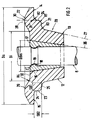
- a spring part 13 surrounding the valve stem 8 and a support part 14 extending transversely to the valve stem 8 for the compression spring 11, which cooperates with a support surface 15 in a supporting manner.
- a conical hub bore 16 is machined into the hub part 13 and is designed to receive a corresponding ring-like valve wedge 17.
- a first radial cross-sectional widening 21 is provided between the support part 14 and the hub part 13.
- the support part 14 has a second axial cross-sectional widening 22 on the side facing away from the compression spring 11. Both cross-sectional extensions can be arranged all around or only locally.
- the first cross-sectional widening 21 is designed in the manner of a step 23 which is led away from the supporting part 14 and comprises step regions 24, 25.
- the transition between the stepped area 24 and 25 is rounded, by means of a radius R1;
- the transitions between the step area 24 and the bearing surface 15 or step area 25 and outside hub part 13 are rounded, which is due to the radii R2 and R3 is shown.
- the radii R1 to R3 are designed differently as follows: R1 ⁇ R2 and R2 ⁇ R3.
- the step area 24 serves as a radial guide for the compression spring 11.
- the hub part 13 is conical, which is illustrated by construction lines 26, 27.
- the hub part B tapers in the direction of the valve plate 7.
- the second cross-sectional extension 22 is an elevation 28 which is delimited by an arcuate line 29.
- the elevation 28 extends between the outer diameter Da - the spring plate 12 - and an inner diameter Di.
- the inner diameter Di is larger than the largest diameter DBm of the hub bore 16.
- the highest point 30 of the elevation 28 intersects a construction line 31 which intersects extends approximately at the same distance between the diameter Da and Di parallel to the valve stem 8 and includes the rectified step region 25.
- the transition of line 29 into an axial boundary 32 of the spring plate 12, which is set back from the highest point 30 or further away from the valve stem end 9, is rounded off, which is represented by the radius R4.
- the distance between the point 30 and the boundary 32 is defined by the dimension Z.
Landscapes
- Engineering & Computer Science (AREA)
- Mechanical Engineering (AREA)
- General Engineering & Computer Science (AREA)
- Valve-Gear Or Valve Arrangements (AREA)
Applications Claiming Priority (2)
| Application Number | Priority Date | Filing Date | Title |
|---|---|---|---|
| DE4230227 | 1992-09-10 | ||
| DE4230227A DE4230227A1 (de) | 1992-09-10 | 1992-09-10 | Ventiltrieb für Brennkraftmaschinen |
Publications (2)
| Publication Number | Publication Date |
|---|---|
| EP0586871A1 true EP0586871A1 (fr) | 1994-03-16 |
| EP0586871B1 EP0586871B1 (fr) | 1996-07-10 |
Family
ID=6467638
Family Applications (1)
| Application Number | Title | Priority Date | Filing Date |
|---|---|---|---|
| EP93112218A Expired - Lifetime EP0586871B1 (fr) | 1992-09-10 | 1993-07-30 | Commande de soupape pour moteur à combustion interne |
Country Status (2)
| Country | Link |
|---|---|
| EP (1) | EP0586871B1 (fr) |
| DE (2) | DE4230227A1 (fr) |
Citations (8)
| Publication number | Priority date | Publication date | Assignee | Title |
|---|---|---|---|---|
| FR2384166A1 (fr) * | 1977-03-16 | 1978-10-13 | Schmitthelm Fa Ernst | Ressort de vehicule a moteur utilisable en tant que ressort de commande de deplacement et en tant que ressort de soupape |
| US4432311A (en) * | 1982-06-11 | 1984-02-21 | Standard Oil Company (Indiana) | Composite valve spring retainer and process |
| JPS59224410A (ja) * | 1983-06-03 | 1984-12-17 | Toyota Motor Corp | 内燃機関用バルブスプリングリテ−ナ |
| WO1989008770A1 (fr) * | 1988-03-10 | 1989-09-21 | Dynamet Technology Inc. | Soupape a champignon en titane |
| JPH0385306A (ja) * | 1989-08-25 | 1991-04-10 | Mazda Motor Corp | バルブリフタの製造方法 |
| JPH03149305A (ja) * | 1989-11-06 | 1991-06-25 | Ngk Spark Plug Co Ltd | バルブリフタ |
| EP0438164A1 (fr) * | 1990-01-18 | 1991-07-24 | Mitsubishi Materials Corporation | Soupape d'un moteur en alliage de titane |
| DE9300820U1 (de) * | 1993-01-22 | 1993-03-11 | Robert Bosch Gmbh, 7000 Stuttgart | Vorrichtung zur Aufnahme mindestens einer Ventilfeder |
Family Cites Families (9)
| Publication number | Priority date | Publication date | Assignee | Title |
|---|---|---|---|---|
| GB1027923A (en) * | 1963-12-26 | 1966-04-27 | Thompson Ramo Wooldridge Inc | Improvements in or relating to locks, in particular valve spring retainer locks |
| US4180030A (en) * | 1977-09-19 | 1979-12-25 | Mcwhirter John A | Valve lock assembly |
| DE3201023C2 (de) * | 1982-01-15 | 1987-01-02 | Daimler-Benz Ag, 7000 Stuttgart | Ventilfederteller für Ventiltriebe von Brennkraftmaschinen |
| DE8506244U1 (de) * | 1985-03-05 | 1986-10-09 | Robert Bosch Gmbh, 7000 Stuttgart | Tassenstößel für Ventiltriebe von Verbrennungsmotoren |
| DE3809954C1 (en) * | 1988-03-24 | 1989-08-24 | Bayerische Motoren Werke Ag, 8000 Muenchen, De | Device for the hydraulic opening of a lifting valve |
| JPH0617642B2 (ja) * | 1988-10-31 | 1994-03-09 | いすゞ自動車株式会社 | 電磁力駆動バルブ制御装置 |
| DE3920729A1 (de) * | 1989-06-24 | 1991-01-10 | Gmb Giesserei & Maschinenbau B | Tassenstoesselkoerper fuer ventilstoessel |
| DE4138985C2 (de) * | 1990-12-07 | 2001-03-22 | Volkswagen Ag | Hydraulische Längenausgleichsvorrichtung, insbesondere Spielausgleichsvorrichtung für ein Hubventil |
| DE4039256C2 (de) * | 1990-12-08 | 1996-05-09 | Schaeffler Waelzlager Kg | Einrichtung zur gleichzeitigen Betätigung zweier Gaswechselventile einer Brennkraftmaschine |
-
1992
- 1992-09-10 DE DE4230227A patent/DE4230227A1/de not_active Ceased
-
1993
- 1993-07-30 DE DE59303186T patent/DE59303186D1/de not_active Expired - Fee Related
- 1993-07-30 EP EP93112218A patent/EP0586871B1/fr not_active Expired - Lifetime
Patent Citations (8)
| Publication number | Priority date | Publication date | Assignee | Title |
|---|---|---|---|---|
| FR2384166A1 (fr) * | 1977-03-16 | 1978-10-13 | Schmitthelm Fa Ernst | Ressort de vehicule a moteur utilisable en tant que ressort de commande de deplacement et en tant que ressort de soupape |
| US4432311A (en) * | 1982-06-11 | 1984-02-21 | Standard Oil Company (Indiana) | Composite valve spring retainer and process |
| JPS59224410A (ja) * | 1983-06-03 | 1984-12-17 | Toyota Motor Corp | 内燃機関用バルブスプリングリテ−ナ |
| WO1989008770A1 (fr) * | 1988-03-10 | 1989-09-21 | Dynamet Technology Inc. | Soupape a champignon en titane |
| JPH0385306A (ja) * | 1989-08-25 | 1991-04-10 | Mazda Motor Corp | バルブリフタの製造方法 |
| JPH03149305A (ja) * | 1989-11-06 | 1991-06-25 | Ngk Spark Plug Co Ltd | バルブリフタ |
| EP0438164A1 (fr) * | 1990-01-18 | 1991-07-24 | Mitsubishi Materials Corporation | Soupape d'un moteur en alliage de titane |
| DE9300820U1 (de) * | 1993-01-22 | 1993-03-11 | Robert Bosch Gmbh, 7000 Stuttgart | Vorrichtung zur Aufnahme mindestens einer Ventilfeder |
Non-Patent Citations (3)
| Title |
|---|
| PATENT ABSTRACTS OF JAPAN vol. 15, no. 257 (M - 1130) 28 June 1991 (1991-06-28) * |
| PATENT ABSTRACTS OF JAPAN vol. 15, no. 374 (M - 1160) 20 September 1991 (1991-09-20) * |
| PATENT ABSTRACTS OF JAPAN vol. 9, no. 100 (M - 376) 2 May 1985 (1985-05-02) * |
Also Published As
| Publication number | Publication date |
|---|---|
| DE4230227A1 (de) | 1994-03-17 |
| EP0586871B1 (fr) | 1996-07-10 |
| DE59303186D1 (de) | 1996-08-14 |
Similar Documents
| Publication | Publication Date | Title |
|---|---|---|
| DE69530396T2 (de) | Titaniummaschinenventil | |
| DE3531890A1 (de) | Nockenwelle | |
| DE69300947T2 (de) | Gebaute Nockenwelle. | |
| EP0643216A1 (fr) | Palier de vilebrequin | |
| DE69612087T2 (de) | Kipphebelvorrichtung für brennkraftmaschine | |
| EP0334064A1 (fr) | Elément dans la distribution d'un moteur à combustion interne | |
| EP0171568B1 (fr) | Piston pour moteur à combustion interne avec bague d'expansion | |
| DE1550336A1 (de) | Hydraulische Daempfungsvorrichtung fuer Ventilstoessel | |
| EP0271638B1 (fr) | Arbre coulé, en particulier arbres à cames | |
| EP2440760A1 (fr) | Piston en métal léger à bol de combustion multi-cavité | |
| DE3009302A1 (de) | Zylinderkopf fuer brennkraftmaschinen | |
| DE3301366A1 (de) | Kolben fuer brennkraftmaschinen | |
| EP0897058A2 (fr) | Piston pour un moteur à combustion interne | |
| EP0586871B1 (fr) | Commande de soupape pour moteur à combustion interne | |
| DE69506775T2 (de) | Ventiljoch mit einer den Verschleiss verringenden Kontaktfläche | |
| DE102012018330A1 (de) | Kurbelwelle zur Anordnung in einem Kurbelgehäuse eines Verbrennungsmotors und Verfahren zur Herstellung | |
| EP0380770A1 (fr) | Joint d'étanchéité pour tige de soupape | |
| DE3937402A1 (de) | Ventilsitzring | |
| DE102018209455A1 (de) | Gegossener Kolben für einen Verbrennungsmotor, aus einem Material auf Eisenbasis | |
| DE3005082A1 (de) | Leichtmetallkolben | |
| EP1099845A2 (fr) | Piston avec une connexion entre un conduit de refroidissement et un alésage d'un axe de piston | |
| EP1920174B1 (fr) | Geometrie d'alesage d'axe de piston continue destinee a un piston d'un moteur a combustion interne | |
| DE3233906A1 (de) | Nockenwelle | |
| EP0777072B1 (fr) | Liaison piston-bielle | |
| DE102019120910A1 (de) | Kipphebel für einen Ventiltrieb einer Nutzfahrzeug-Brennkraftmaschine |
Legal Events
| Date | Code | Title | Description |
|---|---|---|---|
| PUAI | Public reference made under article 153(3) epc to a published international application that has entered the european phase |
Free format text: ORIGINAL CODE: 0009012 |
|
| AK | Designated contracting states |
Kind code of ref document: A1 Designated state(s): DE FR GB IT |
|
| 17P | Request for examination filed |
Effective date: 19940824 |
|
| 17Q | First examination report despatched |
Effective date: 19950516 |
|
| GRAG | Despatch of communication of intention to grant |
Free format text: ORIGINAL CODE: EPIDOS AGRA |
|
| GRAH | Despatch of communication of intention to grant a patent |
Free format text: ORIGINAL CODE: EPIDOS IGRA |
|
| ITF | It: translation for a ep patent filed | ||
| GRAH | Despatch of communication of intention to grant a patent |
Free format text: ORIGINAL CODE: EPIDOS IGRA |
|
| GRAA | (expected) grant |
Free format text: ORIGINAL CODE: 0009210 |
|
| AK | Designated contracting states |
Kind code of ref document: B1 Designated state(s): DE FR GB IT |
|
| REF | Corresponds to: |
Ref document number: 59303186 Country of ref document: DE Date of ref document: 19960814 |
|
| ET | Fr: translation filed | ||
| GBT | Gb: translation of ep patent filed (gb section 77(6)(a)/1977) |
Effective date: 19960820 |
|
| PLBE | No opposition filed within time limit |
Free format text: ORIGINAL CODE: 0009261 |
|
| 26N | No opposition filed | ||
| PGFP | Annual fee paid to national office [announced via postgrant information from national office to epo] |
Ref country code: GB Payment date: 19970721 Year of fee payment: 5 |
|
| PGFP | Annual fee paid to national office [announced via postgrant information from national office to epo] |
Ref country code: DE Payment date: 19970729 Year of fee payment: 5 |
|
| PGFP | Annual fee paid to national office [announced via postgrant information from national office to epo] |
Ref country code: FR Payment date: 19970730 Year of fee payment: 5 |
|
| PG25 | Lapsed in a contracting state [announced via postgrant information from national office to epo] |
Ref country code: GB Free format text: LAPSE BECAUSE OF NON-PAYMENT OF DUE FEES Effective date: 19980730 |
|
| GBPC | Gb: european patent ceased through non-payment of renewal fee |
Effective date: 19980730 |
|
| PG25 | Lapsed in a contracting state [announced via postgrant information from national office to epo] |
Ref country code: FR Free format text: LAPSE BECAUSE OF NON-PAYMENT OF DUE FEES Effective date: 19990331 |
|
| PG25 | Lapsed in a contracting state [announced via postgrant information from national office to epo] |
Ref country code: DE Free format text: LAPSE BECAUSE OF NON-PAYMENT OF DUE FEES Effective date: 19990501 |
|
| REG | Reference to a national code |
Ref country code: FR Ref legal event code: ST |
|
| PG25 | Lapsed in a contracting state [announced via postgrant information from national office to epo] |
Ref country code: IT Free format text: LAPSE BECAUSE OF NON-PAYMENT OF DUE FEES;WARNING: LAPSES OF ITALIAN PATENTS WITH EFFECTIVE DATE BEFORE 2007 MAY HAVE OCCURRED AT ANY TIME BEFORE 2007. THE CORRECT EFFECTIVE DATE MAY BE DIFFERENT FROM THE ONE RECORDED. Effective date: 20050730 |