EP0586969A2 - Verfahren und Vorrichtung zur Bestimmung des Gesamtstickstoffgehaltes mittels elementarer Analyse - Google Patents
Verfahren und Vorrichtung zur Bestimmung des Gesamtstickstoffgehaltes mittels elementarer Analyse Download PDFInfo
- Publication number
- EP0586969A2 EP0586969A2 EP93113605A EP93113605A EP0586969A2 EP 0586969 A2 EP0586969 A2 EP 0586969A2 EP 93113605 A EP93113605 A EP 93113605A EP 93113605 A EP93113605 A EP 93113605A EP 0586969 A2 EP0586969 A2 EP 0586969A2
- Authority
- EP
- European Patent Office
- Prior art keywords
- combustion
- gases
- column
- reactor
- sample
- Prior art date
- Legal status (The legal status is an assumption and is not a legal conclusion. Google has not performed a legal analysis and makes no representation as to the accuracy of the status listed.)
- Granted
Links
Images


Classifications
-
- G—PHYSICS
- G01—MEASURING; TESTING
- G01N—INVESTIGATING OR ANALYSING MATERIALS BY DETERMINING THEIR CHEMICAL OR PHYSICAL PROPERTIES
- G01N30/00—Investigating or analysing materials by separation into components using adsorption, absorption or similar phenomena or using ion-exchange, e.g. chromatography or field flow fractionation
- G01N30/02—Column chromatography
- G01N30/04—Preparation or injection of sample to be analysed
- G01N30/06—Preparation
- G01N30/12—Preparation by evaporation
-
- G—PHYSICS
- G01—MEASURING; TESTING
- G01N—INVESTIGATING OR ANALYSING MATERIALS BY DETERMINING THEIR CHEMICAL OR PHYSICAL PROPERTIES
- G01N31/00—Investigating or analysing non-biological materials by the use of the chemical methods specified in the subgroup; Apparatus specially adapted for such methods
- G01N31/12—Investigating or analysing non-biological materials by the use of the chemical methods specified in the subgroup; Apparatus specially adapted for such methods using combustion
-
- G—PHYSICS
- G01—MEASURING; TESTING
- G01N—INVESTIGATING OR ANALYSING MATERIALS BY DETERMINING THEIR CHEMICAL OR PHYSICAL PROPERTIES
- G01N30/00—Investigating or analysing materials by separation into components using adsorption, absorption or similar phenomena or using ion-exchange, e.g. chromatography or field flow fractionation
- G01N30/02—Column chromatography
- G01N30/04—Preparation or injection of sample to be analysed
- G01N30/06—Preparation
- G01N30/12—Preparation by evaporation
- G01N2030/125—Preparation by evaporation pyrolising
-
- G—PHYSICS
- G01—MEASURING; TESTING
- G01N—INVESTIGATING OR ANALYSING MATERIALS BY DETERMINING THEIR CHEMICAL OR PHYSICAL PROPERTIES
- G01N30/00—Investigating or analysing materials by separation into components using adsorption, absorption or similar phenomena or using ion-exchange, e.g. chromatography or field flow fractionation
- G01N30/02—Column chromatography
- G01N30/62—Detectors specially adapted therefor
- G01N30/64—Electrical detectors
- G01N30/66—Thermal conductivity detectors
-
- Y—GENERAL TAGGING OF NEW TECHNOLOGICAL DEVELOPMENTS; GENERAL TAGGING OF CROSS-SECTIONAL TECHNOLOGIES SPANNING OVER SEVERAL SECTIONS OF THE IPC; TECHNICAL SUBJECTS COVERED BY FORMER USPC CROSS-REFERENCE ART COLLECTIONS [XRACs] AND DIGESTS
- Y10—TECHNICAL SUBJECTS COVERED BY FORMER USPC
- Y10T—TECHNICAL SUBJECTS COVERED BY FORMER US CLASSIFICATION
- Y10T436/00—Chemistry: analytical and immunological testing
- Y10T436/11—Automated chemical analysis
- Y10T436/117497—Automated chemical analysis with a continuously flowing sample or carrier stream
- Y10T436/118339—Automated chemical analysis with a continuously flowing sample or carrier stream with formation of a segmented stream
-
- Y—GENERAL TAGGING OF NEW TECHNOLOGICAL DEVELOPMENTS; GENERAL TAGGING OF CROSS-SECTIONAL TECHNOLOGIES SPANNING OVER SEVERAL SECTIONS OF THE IPC; TECHNICAL SUBJECTS COVERED BY FORMER USPC CROSS-REFERENCE ART COLLECTIONS [XRACs] AND DIGESTS
- Y10—TECHNICAL SUBJECTS COVERED BY FORMER USPC
- Y10T—TECHNICAL SUBJECTS COVERED BY FORMER US CLASSIFICATION
- Y10T436/00—Chemistry: analytical and immunological testing
- Y10T436/17—Nitrogen containing
- Y10T436/176152—Total nitrogen determined
- Y10T436/176921—As part of an elemental analysis
Definitions
- the present invention concerns a process and an apparatus for determining the content of total nitrogen in a sample by means of combustion elemental analysis.
- the classical method for the determination of total nitrogen and proteins in a sample is the one known as wet Kjeldahl method. This method is based on the digestion of the sample with concentrated H2SO4 and subsequent titration with ammonia. Though endowed with the outstanding advantage of enablimg the analysis of samples in the order of 1 - 3 g, the Kjeldahl method has been recently more and more replaced by combustion methods, that allow a more simple process and its almost full automation.
- the methods for combustion elemental analysis substantially provide to perform a flash dynamic combustion of small sample amounts in high excess of oxygen, in presence of catalysts, and the treatment of the thus obtained combustion gases by having them pass, under helium flow as carrier gas, successively through a copper-containing reduction reactor, a trap for CO2 absorption, a trap for water absorption and a gas chromatographic column packed with an adsorbent (e.g. Porapack QS) that has the function of separating nitrogen from other combustion gases.
- the determination of nitrogen eventually takes place by means of a thermal conductivity detector and the function of the Porapack column, besides the aforesaid one, is also that of improving the shape of the N2 peak and of providing the equipment with the necessary pneumatic resistance.
- the aim of the present invention is therefore to make possible to determine total nitrogen content by means of combustion analysis of relatively large samples, of about 100 - 500 mg and up to 1.5 - 2.0 g, also in a fully automated way.
- Said goal is achieved by means of the present invention that concerns a process for determining the nitrogen content of a sample, of the type comprising the combustion of said sample and subsequent reduction of the combustion gases by flowing them in a flow of helium or similar carrier gas through a Cu-containing reactor, characterized in comprising the following steps: making anhydrous the gases coming out from said reduction reactor; flowing said combustion gases through a gas chromatographic column, in order to carry out a gaschromatographic separation of N2 from CH4 possibly present in said combustion gases; removing CO2 from said gases in a CO2 trap; and analyzing the thus treated combustion gases by means of a thermal conductivity detector.
- the detector is kept at a temperature at least equal to that wich permits the full vaporization of water present in said gases coming to the detector, namely at such a temperature as to maintain water under vapour form and simultaneously provide the detector with a sufficient sensitivity.
- the separation on chromatographic column is performed after gases are made anhydrous and before CO2 is removed, and the gases coming out from the CO2 removing means are fed directly to said detector.
- CO2 is removed at the same time of water, by means of anhydrous soda lime, before separation of N2 from CH4.
- the thermal conductivity detector is preferably heated above water boiling point.
- the invention moreover concerns an apparatus for the determination of total nitrogen by means of flash dynamic combustion in a flow of helium or similar carrier gas, comprising a combustion reactor, a reduction reactor, gas drying means, means for CO2 removal from the combustion gases, and a thermal conductivity detector, characterized in that it also comprises, upstream of said detector, a gas chromatographic column packed with a material suitable to separate nitrogen from methane possibly present within said combustion gases.
- the column for nitrogen separation is positioned downstream of the gas drying means and upstream of those for CO2 removal, which are directly connected with said detector, that is provided with means for the control of its temperature.
- H2O and CO2 are both removed from combustion gases by means of a trap containing an hydrous soda lime (CaO + NaOH), provided upstream the gaschromatographic column.
- a trap containing an hydrous soda lime (CaO + NaOH) provided upstream the gaschromatographic column.
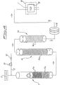
- the apparatus comprises a combustion reactor 1, provided in a known way with means (not shown) for its heating and connected upstream with a line for feeding He or similar carrier gas, as well as a sampler 3 or equivalent means for feeding the samples to be analyzed into reactor 1.
- the reactor 1 is known per se in this branch of the art and is provided with at least an oxidation catalyst of known type and preferably selected among Pt on alumina or similar supported noble metals possibly mixed to copper oxide (CuO); chrome oxide (Cr2O3), cobalt oxide (Co3O4), possibly supported, and mixtures thereof.
- an oxidation catalyst of known type and preferably selected among Pt on alumina or similar supported noble metals possibly mixed to copper oxide (CuO); chrome oxide (Cr2O3), cobalt oxide (Co3O4), possibly supported, and mixtures thereof.
- CuO copper oxide
- Cr2O3 chrome oxide
- Co3O4 cobalt oxide
- two different layers of catalyst 1a and 1b are present.
- the reactor 1 is connected at its outlet port, through a connecting line, to reduction reactor 4, known per se in the art, and containing metal Cu to perform the reduction of the combustion gases and to eliminate oxygen, possibly still present therein.
- a preferred material for this purpose consists in copper wires or in a mixture 4a of copper wires and quartz shavings.
- the reactor 4 is provided in a known way with means (not shown) for its own temperature control.
- the reduction reactor 4 is connected with means 5 to make anhydrous the mixture of gases coming from the reactor 4.
- means 5 constitutes a trap for water and moisture only, of a type known in the art and commercially available, and consisting, for instance, of a container provided with Mg(ClO4)2, magnesium perchlorate, 5a.
- a gaschromatographic column 6 Downstream trap 5, and connected thereto, there is provided a gaschromatographic column 6, to which gases coming out from the trap 5 are fed.
- the column is packed with a material suitable to separate nitrogen, previously formed in reactor 1 and in reduction reactor 4, from methane, CH4, possibly formed by pyrolysis in reactor 1 during the flash dynamic combustion of the sample.
- Column 6 must have relatively large dimensions and in any case such as not to cause excessive pneumatic resistance, since otherwise the correct sample combustion would be jeopardized.
- Preferred dimensions are: length within the range from 80 to 120 cm and internal diameter within the range from 4.0 to 10.0 mm.
- Preferred materials to be used as packing suitable to perform N2/CH4 separation are for example activated carbon and molecular sieves of the Angstrom 5 type. Activated carbon is preferably used.
- Means 7 constitutes a so called trap for carbon dioxide, is known per se in the art, and comprises one or more compounds 7a for carbon dioxide absorption, such as ascarite, NaOH on alumina, commercial soda lime (CaO + NaOH with 10-20% moisture content), and the like.
- Means 7 is directly connected to thermal conductivity detector 8, known per se in the art and used in this field, which is provided with means 9 for temperature control such as for instance an oven or similar device.
- Means 14 where both CO2 and H2O are trapped and removed from combustion gases.
- Means 14 contains anhydrous soda lime 14a, i.e. an anhydrous mixture of CaO and NaOH.
- soda lime on the contrary, contains 10 to 20% of moisture. It was found that while commercial soda lime is suitable only to absorb CO2, anhydrous soda lime allows to absorb and remove from combustion gases both CO2 and H2O. In fact water is absorbed and activates soda lime to absorb also CO2.
- another water trap may be provided between means 14 and column 6 to ensure complete removal of water.
- This trap is known in the art and is preferably the same as trap means 5-5a previously disclosed with reference to fig. 1 embodiment, or may be an anhydrone trap.
- the preferential embodiment of the invention provides on He feeding line 2 a loop 10, known per se in the art and controllably connectable with a feeding line of O2 and with the line 2 itself.
- Figure 2 shows a schematic representation of the loop and of the relevant switching valve, where ports have been indicated with references a to f.
- Loop 10 has a volume within the range from 10 to 200 ml, depending on the weight of the sample to be analyzed. For a sample weighing approximately 50 - 500 mg a 50 ml loop is used; pressure inside the loop will also be controlled as a function of the sample: in the previous case, a pressure equivalent to 150 relative KPa, and more generally, a pressure ranging between 60 and 200 relative KPa will be used.
- Upstream loop 10 there is also provided a flow rate regulator 12, that has the function of keeping He flow to the equipment constant during the whole analysis.
- regulator 12 is particularly useful since the high amounts of samples analyzed lead to increasing amounts of ashes to be deposited in the combustion reactor 1, with subsequent variation of its pneumatic resistance.
- Figure 3 shows in a schematic way a preferential embodiment of sampler, where instead of the known slide there is provided a septum 13 rotatable about its axis from a position where the sample is received (figure 3) to a position where the sample is fed to the combustion reactor 1.
- the second position is coaxial with the first one and corresponds to a rotation of the septum 13 by 180 degrees.
- the sample is weighed and closed in a tin (or equivalent metal) capsule in a known way; then it is fed to the combustion reactor 1 where a flash dynamic combustion takes place in presence of oxygen that is fed, under pulse form, from loop 10 to reactor 1 simultaneously with the introduction of the sample into the reactor 1.
- oxygen present in the loop 10 is fed to the reactor 1 by appropriately switching ports a-f of the aforedescribed switching valve, so as to obtain a "pulsed" conveyance of oxygen and a flash dynamic combustion of the sample.
- N2 nitrogen oxides, CO2, as well as water, SO2, Cl2, HCl and other gases are formed, depending on the content of the sample analyzed, and usually CH4 as well. Methane generation frequently occurs, since the weight of the analyzed sample is relatively high and, differently from the known techniques, combustion is not carried out in high oxygen excess.
- This stage is performed at a temperature within the range from 900 to 1100 degrees C, and preferably at a temperature of 1020 degrees C.
- Halogens, hydrogen chloride and other halogen acids, sulfur dioxide, if present, are adsorbed on the oxidation catalysts and eventual residues on the Co2 copy.
- the thus obtained gases coming from reactor 1 are conveyed to reduction reactor 2, where nitrogen oxides are reduced to N2, and oxygen, if present, is fixed on copper as oxide.
- This stage is carried out at a temperature within the range from 500 to 800 °C and preferably at 700 °C.
- the reduced gases are then fed to means 5, where water present therein is removed, and afterwards conveyed to column 6, that performs the separation between N2 and CH4.
- the gases are fed to the CO2 trap 7, so that carbon dioxide is removed and fixed on basic compounds 7a.
- the detection temperature is generally within the range from 100 to 150 °C and is preferably 120 °C.
- gases coming out from reactor 4 are fed to trap means 14 were both CO2 and water are removed therefrom.
- gases exiting trap means 14 may be passed through a further water trap (not shown) such as means 5 disclosed with reference to fig. 1 embodiment.
- TCD detector 8 After CH4/N2 separation in column 6, gases are fed to TCD detector 8, which is preferably kept at the same conditions above disclosed with reference to fig. 1 embodiment.
- test conditions were as follows: temperature of flash combustion reactor 1020 °C; temperature of reduction reactor 700 °C; O2 loop : 50 ml at 150 relative KPa; gases dried on anhydron; column packed with activated C; CO2 removed on soda lime; TCD detector temperature 120 degrees C. TABLE I COMPOUND QUANTITY (mg) AVERAGE N.% STAND. DEV. REL. STAND. DEV.
Landscapes
- Chemical & Material Sciences (AREA)
- Health & Medical Sciences (AREA)
- Life Sciences & Earth Sciences (AREA)
- General Health & Medical Sciences (AREA)
- Analytical Chemistry (AREA)
- Biochemistry (AREA)
- Physics & Mathematics (AREA)
- General Physics & Mathematics (AREA)
- Immunology (AREA)
- Pathology (AREA)
- Engineering & Computer Science (AREA)
- Combustion & Propulsion (AREA)
- Molecular Biology (AREA)
- Investigating Or Analyzing Non-Biological Materials By The Use Of Chemical Means (AREA)
Applications Claiming Priority (2)
| Application Number | Priority Date | Filing Date | Title |
|---|---|---|---|
| ITMI922034A IT1256355B (it) | 1992-08-31 | 1992-08-31 | Procedimento e apparecchiatura per la determinazione dell'azoto totale mediante analisi elementare |
| ITMI922034 | 1992-08-31 |
Publications (3)
| Publication Number | Publication Date |
|---|---|
| EP0586969A2 true EP0586969A2 (de) | 1994-03-16 |
| EP0586969A3 EP0586969A3 (de) | 1994-04-27 |
| EP0586969B1 EP0586969B1 (de) | 1999-03-10 |
Family
ID=11363894
Family Applications (1)
| Application Number | Title | Priority Date | Filing Date |
|---|---|---|---|
| EP93113605A Expired - Lifetime EP0586969B1 (de) | 1992-08-31 | 1993-08-25 | Verfahren und Vorrichtung zur Bestimmung des Gesamtstickstoffgehaltes mittels Elementaranalyse |
Country Status (4)
| Country | Link |
|---|---|
| US (1) | US5612225A (de) |
| EP (1) | EP0586969B1 (de) |
| DE (1) | DE69323820T2 (de) |
| IT (1) | IT1256355B (de) |
Cited By (13)
| Publication number | Priority date | Publication date | Assignee | Title |
|---|---|---|---|---|
| EP0940677A1 (de) * | 1998-03-04 | 1999-09-08 | THERMOQUEST ITALIA S.p.A. | Verfahren und Gerät zur elementaren Analyse |
| EP1061366A3 (de) * | 1999-05-07 | 2001-10-24 | ThermoQuest Italia S.p.A. | Verfahren und Vorrichtung zur elementaren Analyse mit Sauerstoffsteuerung |
| EP0989401A3 (de) * | 1998-09-23 | 2002-11-20 | Eurovector S.p.A. | Verfahren und Vorrichtungen zur Verbesserung der Flash-dynamischen Verbrennungsreaktion für die Elementaranalyse von C H N S O |
| US6653143B2 (en) | 1998-03-04 | 2003-11-25 | Thermoquest Italia S.P.A. | Process and device of elemental analysis |
| WO2009112199A1 (de) * | 2008-03-12 | 2009-09-17 | Lar Process Analysers Ag | Messverfahren und messanordnung zur bestimmung des gehalts eines chemischen elements oder eines anderen wasserqualitätsparameters in frisch- oder abwasser |
| CN105842370A (zh) * | 2016-05-27 | 2016-08-10 | 鼎泰(湖北)生化科技设备制造有限公司 | 一种具有串、并联除水机构且用于定氮分析的设备 |
| CN105842385A (zh) * | 2016-05-27 | 2016-08-10 | 鼎泰(湖北)生化科技设备制造有限公司 | 一种自动除水型定氮分析仪 |
| CN106053712A (zh) * | 2016-05-27 | 2016-10-26 | 鼎泰(湖北)生化科技设备制造有限公司 | 一种具有串、并联净化机构且用于定氮分析的系统 |
| CN106093277A (zh) * | 2016-05-27 | 2016-11-09 | 鼎泰(湖北)生化科技设备制造有限公司 | 一种具有并、串联除水净化机构的总氮分析设备 |
| CN106092946A (zh) * | 2016-05-27 | 2016-11-09 | 鼎泰(湖北)生化科技设备制造有限公司 | 一种用于定氮分析且具有串联除水净化机构的系统 |
| CN106093278A (zh) * | 2016-05-27 | 2016-11-09 | 鼎泰(湖北)生化科技设备制造有限公司 | 一种用于测定氮含量的方法 |
| CN106093279A (zh) * | 2016-05-27 | 2016-11-09 | 鼎泰(湖北)生化科技设备制造有限公司 | 一种具有串、并联除水净化功能的总氮分析系统 |
| CN111175401A (zh) * | 2020-01-15 | 2020-05-19 | 中国水稻研究所 | 一种测定土壤溶液中温室气体含量二维分布的方法 |
Families Citing this family (20)
| Publication number | Priority date | Publication date | Assignee | Title |
|---|---|---|---|---|
| US6627155B1 (en) * | 1998-06-12 | 2003-09-30 | Horiba, Ltd. | Combustion furnace system for analyzing elements in a sample |
| US6503956B2 (en) | 2001-01-11 | 2003-01-07 | Chevron U.S.A. Inc. | Determination of heteroatom content in Fischer-Tropsch wax |
| US6635171B2 (en) | 2001-01-11 | 2003-10-21 | Chevron U.S.A. Inc. | Process for upgrading of Fischer-Tropsch products |
| US6652625B1 (en) | 2002-07-24 | 2003-11-25 | Perkin Elmer Instruments Llc | Analyte pre-concentrator for gas chromatography |
| US6814785B2 (en) * | 2002-07-24 | 2004-11-09 | Perkinelmer Instruments Llc | Analyte pre-concentrator for gas chromatography |
| JP4538622B2 (ja) * | 2003-07-29 | 2010-09-08 | オルガノ株式会社 | ガス分離装置 |
| US7410558B2 (en) * | 2003-09-30 | 2008-08-12 | Perkinelmer Las, Inc. | Method and apparatus for determining a total concentration of a component in a mixture of components |
| ITMI20040740A1 (it) * | 2004-04-15 | 2004-07-15 | Ecoenergetics S R L | Analizzatore automatico per la rilevazione di azoto proveniente da composti organici |
| US7623946B2 (en) * | 2005-09-12 | 2009-11-24 | Exxonmobil Research And Engineering Company | System and method that will synchronize data acquisition and modulation in a comprehensive two (multi) dimensional chromatography (separation) system to enable quantitative data analysis |
| ITMI20060813A1 (it) * | 2006-04-21 | 2007-10-22 | Thermo Electron Spa | Dispositivo di adsorbimento di co2 per strumenti di analisi elementare. |
| US7735352B2 (en) * | 2006-05-16 | 2010-06-15 | Alliant Techsystems Inc. | Multi-dimensional portable gas chromatograph system |
| US7635005B2 (en) * | 2006-05-16 | 2009-12-22 | Alliant Techsystems Inc. | Very small high pressure regulator |
| US7524363B2 (en) * | 2006-05-16 | 2009-04-28 | Alliant Techsystems Inc. | Gas chromatograph column assembly |
| US7485176B2 (en) * | 2006-05-16 | 2009-02-03 | Alliant Techsystems Inc. | Compact thermal conductivity detector |
| JP2013160594A (ja) * | 2012-02-03 | 2013-08-19 | Horiba Ltd | 元素分析装置 |
| DE202015004524U1 (de) * | 2015-06-24 | 2016-09-29 | C. Gerhardt GmbH & Co. KG | Analyseeinrichtung für die Elementaranalyse |
| EP3193165A1 (de) * | 2016-01-18 | 2017-07-19 | C. Gerhardt GmbH & Co. KG | Verfahren zur elementaranalyse |
| GB201608643D0 (en) * | 2016-05-17 | 2016-06-29 | Thermo Fisher Scient Bremen | Elemental analysis system and method |
| CN111141859A (zh) * | 2020-02-19 | 2020-05-12 | 长沙开元仪器有限公司 | 一种肥料中氮元素的分析系统及方法 |
| CN111521639A (zh) * | 2020-05-13 | 2020-08-11 | 中天钢铁集团有限公司 | 杜马斯燃烧法测定合金中氮含量的燃烧方法 |
Family Cites Families (16)
| Publication number | Priority date | Publication date | Assignee | Title |
|---|---|---|---|---|
| US3304159A (en) * | 1963-01-28 | 1967-02-14 | Hewlett Packard Co | Gas chromatographic analysis method for c, h, and n content in solid organic compounds |
| US3698869A (en) * | 1965-08-20 | 1972-10-17 | Perkin Elmer Corp | Analysis of gaseous mixtures |
| FR1528032A (fr) * | 1967-04-26 | 1968-06-07 | Pechiney Saint Gobain | Appareil pour la microanalyse automatique et simultanée du carbone de l'hydrogène et de l'azote ou de l'hydrogène et de l'oxygène dans les substances organiques |
| US3892528A (en) * | 1973-04-02 | 1975-07-01 | Oceanography Int Corp | Method and apparatus for vaporizing liquids to be contacted with a carrier gas |
| US3877875A (en) * | 1973-07-19 | 1975-04-15 | Beckman Instruments Inc | Nitrogen constituent analysis |
| JPS51134189A (en) * | 1975-05-15 | 1976-11-20 | Sumitomo Chem Co Ltd | Measuring method of the total carbon volume |
| CA1023969A (en) * | 1975-12-08 | 1978-01-10 | Robert J. Flett | Preparation and measurement of ultra micro amounts of nitrogen |
| US4070115A (en) * | 1976-03-26 | 1978-01-24 | Humphrey Instruments, Inc. | Lens meter |
| US4054414A (en) * | 1976-11-30 | 1977-10-18 | Villanova University | Gas chromatographic method for the multi-elemental microanalysis of organic materials |
| US4332591A (en) * | 1978-01-19 | 1982-06-01 | Sumitomo Chemical Company, Limited | Analytical method and apparatus for the determination of total nitrogen contents in aqueous systems |
| US4234315A (en) * | 1978-09-29 | 1980-11-18 | Phillips Petroleum Company | Gas chromatographic analysis method and apparatus |
| JPS55155249A (en) * | 1979-05-23 | 1980-12-03 | Sumitomo Chem Co Ltd | Method and apparatus of analysis of total nitrogen |
| JPS5784355A (en) * | 1980-11-13 | 1982-05-26 | Sumitomo Chem Co Ltd | Element analyzing method and device therefor |
| US4467038A (en) * | 1981-11-30 | 1984-08-21 | Phillips Petroleum Company | Predetector reservoir for chromatographic analysis instrument |
| US4525328A (en) * | 1982-03-05 | 1985-06-25 | Leco Corporation | Carbon, hydrogen, and nitrogen analyzer |
| US4650499A (en) * | 1985-11-27 | 1987-03-17 | Phillips Petroleum Company | Gas chromatographic apparatus and method |
-
1992
- 1992-08-31 IT ITMI922034A patent/IT1256355B/it active IP Right Grant
-
1993
- 1993-08-25 DE DE69323820T patent/DE69323820T2/de not_active Expired - Fee Related
- 1993-08-25 EP EP93113605A patent/EP0586969B1/de not_active Expired - Lifetime
-
1995
- 1995-06-07 US US08/473,126 patent/US5612225A/en not_active Expired - Fee Related
Cited By (14)
| Publication number | Priority date | Publication date | Assignee | Title |
|---|---|---|---|---|
| EP0940677A1 (de) * | 1998-03-04 | 1999-09-08 | THERMOQUEST ITALIA S.p.A. | Verfahren und Gerät zur elementaren Analyse |
| US6653143B2 (en) | 1998-03-04 | 2003-11-25 | Thermoquest Italia S.P.A. | Process and device of elemental analysis |
| EP0989401A3 (de) * | 1998-09-23 | 2002-11-20 | Eurovector S.p.A. | Verfahren und Vorrichtungen zur Verbesserung der Flash-dynamischen Verbrennungsreaktion für die Elementaranalyse von C H N S O |
| EP1061366A3 (de) * | 1999-05-07 | 2001-10-24 | ThermoQuest Italia S.p.A. | Verfahren und Vorrichtung zur elementaren Analyse mit Sauerstoffsteuerung |
| US6441365B1 (en) | 1999-05-07 | 2002-08-27 | Thermoquest Italia S.P.A. | Process and apparatus for elemental analysis with oxygen control |
| WO2009112199A1 (de) * | 2008-03-12 | 2009-09-17 | Lar Process Analysers Ag | Messverfahren und messanordnung zur bestimmung des gehalts eines chemischen elements oder eines anderen wasserqualitätsparameters in frisch- oder abwasser |
| CN105842370A (zh) * | 2016-05-27 | 2016-08-10 | 鼎泰(湖北)生化科技设备制造有限公司 | 一种具有串、并联除水机构且用于定氮分析的设备 |
| CN105842385A (zh) * | 2016-05-27 | 2016-08-10 | 鼎泰(湖北)生化科技设备制造有限公司 | 一种自动除水型定氮分析仪 |
| CN106053712A (zh) * | 2016-05-27 | 2016-10-26 | 鼎泰(湖北)生化科技设备制造有限公司 | 一种具有串、并联净化机构且用于定氮分析的系统 |
| CN106093277A (zh) * | 2016-05-27 | 2016-11-09 | 鼎泰(湖北)生化科技设备制造有限公司 | 一种具有并、串联除水净化机构的总氮分析设备 |
| CN106092946A (zh) * | 2016-05-27 | 2016-11-09 | 鼎泰(湖北)生化科技设备制造有限公司 | 一种用于定氮分析且具有串联除水净化机构的系统 |
| CN106093278A (zh) * | 2016-05-27 | 2016-11-09 | 鼎泰(湖北)生化科技设备制造有限公司 | 一种用于测定氮含量的方法 |
| CN106093279A (zh) * | 2016-05-27 | 2016-11-09 | 鼎泰(湖北)生化科技设备制造有限公司 | 一种具有串、并联除水净化功能的总氮分析系统 |
| CN111175401A (zh) * | 2020-01-15 | 2020-05-19 | 中国水稻研究所 | 一种测定土壤溶液中温室气体含量二维分布的方法 |
Also Published As
| Publication number | Publication date |
|---|---|
| EP0586969A3 (de) | 1994-04-27 |
| ITMI922034A1 (it) | 1994-03-03 |
| EP0586969B1 (de) | 1999-03-10 |
| IT1256355B (it) | 1995-12-01 |
| DE69323820D1 (de) | 1999-04-15 |
| DE69323820T2 (de) | 1999-11-11 |
| ITMI922034A0 (it) | 1992-08-31 |
| US5612225A (en) | 1997-03-18 |
Similar Documents
| Publication | Publication Date | Title |
|---|---|---|
| EP0586969A2 (de) | Verfahren und Vorrichtung zur Bestimmung des Gesamtstickstoffgehaltes mittels elementarer Analyse | |
| EP0419167B1 (de) | Analysator von Isotopenzusammensetzungen | |
| EP0024566B1 (de) | Apparat für die Analyse von in Metallen enthaltenem Sauerstoff, Stickstoff und Wasserstoff | |
| EP0317299A2 (de) | Vorrichtung und Verfahren zur Identifizierung von Gerüchen | |
| US6636811B1 (en) | Method and device for identifying gaseous compounds | |
| EP0729577A1 (de) | Isotopenzusammensetzungsanalysator | |
| EP1586895B1 (de) | Analyseur automatisé pour la détermination de la teneur en azote des composants organiques | |
| JP5396245B2 (ja) | 元素分析用前処理装置及び元素分析装置 | |
| JPS63243864A (ja) | ガスクロマトグラフ質量分析計インタ−フエイス | |
| US11047838B2 (en) | Method for elemental analysis | |
| US5429946A (en) | Process and apparatus for elemental analysis of halogens | |
| Ferioli et al. | Analytical characterisation of hashish samples | |
| US20010018218A1 (en) | Process and device of elemental analysis | |
| Zolotov et al. | Determination of platinum metals by X-ray fluorescence, atomic emission and atomic absorption spectrometry after preconcentration with a polymeric thioether | |
| Morie | Some factors that affect the diffusion of carbon monoxide out of cigarettes | |
| Watling et al. | Continuous hydride generation in inductively coupled plasma atomic emission spectrometry using a dual platinum grid nebuliser system | |
| EP0940677B1 (de) | Verfahren und Gerät zur elementaren Analyse | |
| JP4833052B2 (ja) | 酸素雰囲気で融解処理された試料中の元素分析方法および元素分析装置 | |
| CA1084731A (en) | Method for high resolution gas chromatography | |
| SU559171A1 (ru) | Способ анализа состава веществ | |
| Förstel et al. | Preparation of oxygen samples for 18O16O measurements by a combined gas chromatography-burning technique | |
| Kulesheva et al. | Study of the Adsorption of Oxygen by Powdered Silver | |
| JP2874307B2 (ja) | プロセスガスクロマトグラフの校正方法 | |
| JPH09184833A (ja) | 硫黄含有試料中の酸素および/または窒素の分析装置 | |
| JPH02285257A (ja) | ガス分析装置 |
Legal Events
| Date | Code | Title | Description |
|---|---|---|---|
| PUAI | Public reference made under article 153(3) epc to a published international application that has entered the european phase |
Free format text: ORIGINAL CODE: 0009012 |
|
| PUAL | Search report despatched |
Free format text: ORIGINAL CODE: 0009013 |
|
| AK | Designated contracting states |
Kind code of ref document: A2 Designated state(s): DE FR GB IT SE |
|
| AK | Designated contracting states |
Kind code of ref document: A3 Designated state(s): DE FR GB IT SE |
|
| 17P | Request for examination filed |
Effective date: 19941012 |
|
| 17Q | First examination report despatched |
Effective date: 19970305 |
|
| RAP1 | Party data changed (applicant data changed or rights of an application transferred) |
Owner name: THERMOQUEST ITALIA S.P.A. |
|
| GRAG | Despatch of communication of intention to grant |
Free format text: ORIGINAL CODE: EPIDOS AGRA |
|
| GRAG | Despatch of communication of intention to grant |
Free format text: ORIGINAL CODE: EPIDOS AGRA |
|
| GRAH | Despatch of communication of intention to grant a patent |
Free format text: ORIGINAL CODE: EPIDOS IGRA |
|
| GRAH | Despatch of communication of intention to grant a patent |
Free format text: ORIGINAL CODE: EPIDOS IGRA |
|
| GRAA | (expected) grant |
Free format text: ORIGINAL CODE: 0009210 |
|
| AK | Designated contracting states |
Kind code of ref document: B1 Designated state(s): DE FR GB IT SE |
|
| PG25 | Lapsed in a contracting state [announced via postgrant information from national office to epo] |
Ref country code: SE Free format text: THE PATENT HAS BEEN ANNULLED BY A DECISION OF A NATIONAL AUTHORITY Effective date: 19990310 Ref country code: IT Free format text: LAPSE BECAUSE OF FAILURE TO SUBMIT A TRANSLATION OF THE DESCRIPTION OR TO PAY THE FEE WITHIN THE PRE;WARNING: LAPSES OF ITALIAN PATENTS WITH EFFECTIVE DATE BEFORE 2007 MAY HAVE OCCURRED AT ANY TIME BEFORE 2007. THE CORRECT EFFECTIVE DATE MAY BE DIFFERENT FROM THE ONE RECORDED.SCRIBED TIME-LIMIT Effective date: 19990310 Ref country code: FR Free format text: LAPSE BECAUSE OF FAILURE TO SUBMIT A TRANSLATION OF THE DESCRIPTION OR TO PAY THE FEE WITHIN THE PRESCRIBED TIME-LIMIT Effective date: 19990310 |
|
| REF | Corresponds to: |
Ref document number: 69323820 Country of ref document: DE Date of ref document: 19990415 |
|
| EN | Fr: translation not filed | ||
| PG25 | Lapsed in a contracting state [announced via postgrant information from national office to epo] |
Ref country code: GB Free format text: LAPSE BECAUSE OF NON-PAYMENT OF DUE FEES Effective date: 19990825 |
|
| PLBE | No opposition filed within time limit |
Free format text: ORIGINAL CODE: 0009261 |
|
| 26N | No opposition filed | ||
| GBPC | Gb: european patent ceased through non-payment of renewal fee |
Effective date: 19990825 |
|
| PGFP | Annual fee paid to national office [announced via postgrant information from national office to epo] |
Ref country code: DE Payment date: 20070830 Year of fee payment: 15 |
|
| PG25 | Lapsed in a contracting state [announced via postgrant information from national office to epo] |
Ref country code: DE Free format text: LAPSE BECAUSE OF NON-PAYMENT OF DUE FEES Effective date: 20090303 |