EP0587249B1 - Rekonfigurationsverfahren des Bestrahlungsfeldes einer Antenne in einem Satellitennetz - Google Patents
Rekonfigurationsverfahren des Bestrahlungsfeldes einer Antenne in einem Satellitennetz Download PDFInfo
- Publication number
- EP0587249B1 EP0587249B1 EP93202609A EP93202609A EP0587249B1 EP 0587249 B1 EP0587249 B1 EP 0587249B1 EP 93202609 A EP93202609 A EP 93202609A EP 93202609 A EP93202609 A EP 93202609A EP 0587249 B1 EP0587249 B1 EP 0587249B1
- Authority
- EP
- European Patent Office
- Prior art keywords
- coverage
- station
- satellite
- coverages
- stations
- Prior art date
- Legal status (The legal status is an assumption and is not a legal conclusion. Google has not performed a legal analysis and makes no representation as to the accuracy of the status listed.)
- Expired - Lifetime
Links
Images



Classifications
-
- H—ELECTRICITY
- H04—ELECTRIC COMMUNICATION TECHNIQUE
- H04B—TRANSMISSION
- H04B7/00—Radio transmission systems, i.e. using radiation field
- H04B7/14—Relay systems
- H04B7/15—Active relay systems
- H04B7/204—Multiple access
- H04B7/2041—Spot beam multiple access
Definitions
- the present invention relates very generally to telecommunications between earth transceiver stations via a satellite.
- the invention relates to a method for reconfiguring satellite radio beam coverage in order to dynamically manage beam coverage according to requests from earth stations, while maintaining beam coverage of minimum size to satisfy a balance sheet. of power within the satellite.
- the radio coverage of the satellite is reconfigured according to the volume traffic variations and the positions of fixed or mobile earth stations using the satellite as radio relay. This reconfiguration adapts the payload resources in the satellite to the characteristics of the traffic at all times.
- the invention is particularly well suited to the case of sporadic traffic, such as those generated by VSAT (Very Small Aperture Terminal) stations or mobile stations.
- Another quality of the satellite linked to its extensive coverage and therefore to its broadcasting or collection capacity was thus taken advantage of: instead of transmitting signals from one point to another, a transmitter of a given station can transmit to receivers of stations in large numbers via satellite, or conversely stations in large numbers can transmit to a central station.
- the first satellites designed use single-beam type antennas which have certain drawbacks: either the satellite provides coverage of a large terrestrial surface, but the gain of the satellite antenna is limited by the beam opening angle; either the satellite covers a small area of the earth, and in this case, the antenna gain is higher but the beam cannot cover stations that are too distant geographically.
- a single-beam satellite it must be chosen between, on the one hand, extended coverage but with a low antenna gain, and therefore links with high error rates, and on the other hand, reduced coverage with a high antenna gain but not allowing interconnection of stations that are too far away.
- Multibeam antenna techniques combine these two alternatives.
- the satellite coverage is extended because it results from the juxtaposition of several beams, and each beam offers an antenna gain the higher the beam opening is reduced.
- multibeam antennas on board a satellite are made up of radiating elements, and associated respectively with beam shaping networks.
- a beam shaping network supplying the radiating elements of an antenna further comprises phase shifters and power dividers making it possible to configure the associated antenna in a particular way. In reception as much as in transmission, the antenna is thus programmed for specific radiation patterns.
- a radiation pattern is expressed in particular by a gain as a function of an angle relative to the axis of the antenna.
- predetermined coverage areas are cyclically illuminated by the same antenna beam whose orientation is controlled by particular control values programming a beam conformation network.
- the stations located in a given coverage area only transmit or receive information when said area is illuminated by the beam.
- at least two beams are necessary at all times: one to establish an uplink from the transmitters of the earth stations to the satellite, and the other to establish a link. downlink from satellite to earth station receivers.
- the first two steps in the first alternative can be replaced by the determination and reduction steps (a 10 ' ) and (a 11' ) set out above.
- the control station includes digital simulation processing means making it possible to carry out all the calculations relating to the aforementioned steps.
- the beam covers are memorized at all times in the control station in the form of discrete points associated with contour points said covers, in a transformed reference defined by: where ⁇ and ⁇ respectively designate angular coordinates in elevation and azimuth in a spherical coordinate system centered on the radiating means, that is to say the antenna of the satellite.
- the determination of a coverage closest to said each station comprises, in addition, an incrementation of a directing coefficient to define a bundle of straight lines passing through a point associated with said each station and intercepting sides of coverage polygons, a calculation of the distances between said point associated with said each station and the intersections of the lines with the sides of the polygons, and a selection of the minimum distance of the calculated distances in order to determine the coverage of which one side is closest to said associated point.
- the reduction in size of one of said other covers may further comprise, for each side of a polygon associated with said other cover in the transformed coordinate system, the sub-steps set out in claim 7 or 8.
- the station charge exchange between said given coverage and said adjacent coverage provided in step (a 21 ) preferably comprises the sub-steps set out in claim 9.
- a satellite 1 antenna On reception, a satellite 1 antenna is configured to ensure constant global coverage CG of a given earth surface including all earth stations S 1 to S 8 and the control station SC, thanks to a beamwidth angle FC very open.
- Any earth station S 1 to S 8 wishing to establish a link through the satellite network to transmit information to another earth station sends a connection establishment request to the control station SC via the satellite 1.
- This request is supported by a signaling channel of the global coverage reception beam FC in the direction of satellite 1, to be retransmitted towards the control station SC.
- the control station SC develops, by simulation, new beam covers of satellite 1, both in transmission and in reception, and transmits, by a specific link, control values of conformation networks of beams to program the beam coverage of several antennas with variable coverage of satellite 1.
- the earth station S 5 must transmit information to the station called S 1 ; it is necessary both to reconfigure, in transmission, the downlink beam FD whose transmission coverage CD does not include the station S 5 , and, in reception, the uplink beam FM whose reception coverage CM does not include not station S 1 .
- control values of the beam shaping networks transmitted by the control station SC control, in the satellite, phase shifters and dividers power transmitting / receiving signals to / from radiating elements of transmitting / receiving antennas of satellite 1, respectively.
- the invention is not limited to the insertion of earth stations into new beam coverage, but also includes the reduction of coverage in order to maintain a high antenna gain and therefore good quality links in terms of transmission rate. 'error, the exchange of capacity between adjacent covers in order to remedy the capacity saturation of a beam, etc.
- an antenna with radiating elements for example of the plate type, comprises a plurality of radiating elements ER 1 to ER N , which can be very high in number, distributed over the surface of the antenna.
- the antenna assumed here to operate in transmission, is preceded by a beam conformation network (not shown).
- This beam shaping network also includes variable power dividers and variable microwave phase shifters respectively associated with the radiating elements and controlled by means of beam orientation modification. By appropriate choices of phase shifts in phase shifters and of power distributions across the power dividers, various antenna radiation patterns are produced.
- phase shifts and power distributions modify the inclination of the phase plane relative to the surface of the radiating elements and the gain of the antenna, and thus the orientation of the beam produced by the antenna and the opening of the beam.
- Different radiation patterns are thus obtained in terms of gain as a function of the angle ⁇ between the direction of the radiation and the z'z axis of the antenna.
- the radiating elements are very slightly spaced apart for optimal coupling and, at each point M located at a given distance from the antenna, the radiation results from the respective contribution of each radiating element.
- phase shifters and power dividers are adequately controlled to give optimal gain to the antenna for a given solid angle of the antenna of satellite 1, defining a beam reception.
- control station SC includes calculation means for extracting these control values which are transmitted, via the specific link, to the beam shaping networks in the satellite 1. Numerical methods of calculation of these control values , from desired beam covers, are for example, the min-max method and the least squares method.
- control station SC stores the contours of beam covers in a discrete form.
- gain calculations on the coverage contour of each beam are carried out only for a certain number of discrete points of this contour.
- an angular spacing is chosen to define a "step" between each discrete point of the representation of the cover. This angular spacing results from a compromise between the precision of the treatments, or calculations, carried out on the coverage contours and the speed of these treatments by digital processing means in the control station SC.
- the actual coverage can be obtained using min-max or least squares algorithms.
- the actual coverage makes it possible to deduce the control values of the beam shaping networks.
- a Cartesian coordinate system O, x, y, z
- any point P in space is identified by spherical coordinates ( ⁇ , ⁇ , r ).
- ⁇ , ⁇ , r spherical coordinates
- any calculation result carried out in the transformed coordinate system (u, v) is transposable in the coordinate system with spherical coordinates.
- each beam coverage contour is stored in the form of a plurality of discrete points of said contour in the transformed sampling frame (u, v).
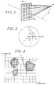
- any beam coverage, of substantially circular shape on the ground is represented in a discrete form in the transformed reference frame (u, v) by a closed polygonal contour C 1 , C 2 , C 3 represented by line segments.
- Each contour constitutes an isogain contour within which the gain is greater than a guaranteed minimum gain corresponding to a given error rate or quality.
- a station S k having to establish a link with a station S l in order to transmit information to it, transmits beforehand a request for establishment of a link further comprising its address k and the address l from the earth station called S l .
- This request supported by the signaling channel of the global coverage reception beam CG, is received by satellite 1 and retransmitted to the control station SC.
- the control station SC comprises simulation means for implementing the method according to the invention, and in particular means for storing in the coordinate system (u, v) the digital discrete image of the overall ground coverage seen from the satellite .
- the station SC produces a transmission authorization, or a rejection, or even a request to put the request on hold.
- This response is retransmitted, via the signaling channel, to the earth station S k .
- the beam shaping networks associated with the antennas of satellite 1 are reconfigured both at reception so that the calling earth station S k is included in a gain reception coverage minimum of a satellite 1 antenna, and in transmission so that the transmission beam coverage of a satellite 1 antenna covers the called station with minimum antenna gain.
- This last point is underlined in step E O1 of the algorithm of FIG. 5.
- one of two series of following steps E 1 and E 2 is carried out, in simulation by the station SC, for the calling station S k and for the station called S l respectively, and the authorization to transmit or the rejection of the request is produced by the station SC respectively according to whether the simulation according to the algorithm of FIG.
- the two stations S k and S l are designated by station S, while knowing that the following series of substeps must be simulated for the two stations S k and S l , and give results of authorization simulated respectively for the two stations S k and S l so that the authorization to transmit is transmitted by the control station SC to the station S k .
- the covers of all the beams, both in transmission and in reception, of satellite 1 are stored in discrete form as presented in FIG. 4, that is to say in the form of polygons in the transformed coordinate system (u, v).
- the "geographic" position in the coordinate system (u, v), and the associated address of each station are also stored in the station SC.
- a final initial sub-step of processing E O2 of the algorithm consists in studying the membership of the station S with transmission coverage (when S is calling) or reception coverage (when S is called) with the given configuration of the beam shaping networks upon receipt of the connection establishment request.
- the station S does not belong to a beam coverage C i , the other alternative being presented later with reference to FIG. 11.
- the station S is, like the stations S 1 or S 5 in Figure 1, located outside of a beam cover.
- a modification of the coverage of one of the beams is therefore necessary to include the station S.
- the coverage of the beams delimit terrestrial geographic zones whose contours define boundaries on which connections with satellite 1 are guaranteed with minimum quality in terms of antenna gain, or transmission error rate. These boundaries also define geographic points where a minimum quality of connection with satellite 1 is thus guaranteed.
- Two cases are envisaged according to the present invention for the choice of the beam coverage to be modified in order to include the station S: or else, according to a first case, this beam coverage is the coverage having the lowest surface area among all the coverage of the satellite beams, or, in a second case, this coverage is the closest coverage to station S.
- the two cases are treated separately by the control station and the solution offering the highest antenna gain high in simulation for station S is selected (substep E 15 ).
- the choice of the smaller area coverage results from the following observation: the smaller area coverage offers the gain highest antenna and is therefore most suitable for "enlarging" to include station S while maintaining sufficient antenna gain. It is recalled that each beam offers an antenna gain the higher the beam opening angle is low.
- the determination of the coverage of the smallest area is carried out in the control station SC by locating, in a representation of the type shown in FIG. 4, the coverage having a minimum geographic coverage by area calculation.
- each Ci of the coverages is reduced according to a method (sub-step E 12a ) described with reference to FIG. 8, and a modification of the determined coverage C d is simulated to include the station S at its border (sub- step E 13a ).
- the coverage C d closest to the station S is first determined ( substep E 11b ). Then, in the same way as in the first previous case, each C i of the covers, with 1 ⁇ i ⁇ I and I being the total number of coverage is reduced (sub-step E 12b ), and an insertion of the station S into the determined coverage C d is simulated (sub-step E 13b ). Depending on the gain obtained for station S, at the border of the modified cover C d to include it, other coverages are reduced, and the theoretical gain results for station S in the respective modified coverages are recorded. . It should be noted that the reduction, in transmission or reception, of a beam coverage of the satellite, has the effect of reducing the power used by the satellite for this coverage.
- the reduction in coverage C i allows the expansion of another coverage, in this case C d .
- Priorities can be defined for the order of selection of the covers C i to be reduced. So, for example, it may seem interesting to initially reduce the coverage C d .
- Substages E 11a to E 14a relating to the first case are first studied.
- step E 11a for determining the coverage of the smallest area is carried out in the transformed reference frame (u, v) by area calculation.
- any beam coverage is represented by a polygon , and for example the beam coverage represented in FIG. 8 is delimited by a polygon having six vertices I 1 , I 2 , I 3 , I 4 , I 5 and I 6 .
- a set of parametric lines ( ⁇ o ) to ( ⁇ n ) parallel to this side is determined.
- the control station SC selects the first of the parametric lines including an active earth station S i using the discrete representation of the coverage C i stored in the control station SC.
- the cover (I 1 , I 2 , I 3 , I 4 , I 5 , I 6 ) is transformed into (I 1 , I 2 , I 3 , I 4 , S j , I 5 , I 6 ) for the side (I 4 , I 5 ).
- stations S j such as two stations S j1 and S j2 , belong simultaneously to a first parametric straight line of the bundle of lines including at least one station.
- S j (S j1 or S j2 ), I 5 , I 6 ) the station, S j1 or S j2 is chosen for which the sum is minimum distances (d (S j , I 4 ) + d (S j , I 5 )), where d denotes the distance operator.
- This reduced polygon corresponds to an area for which the reduction in coverage is minimal.
- the cover (I 1 , I 2 , I 3 , I 4 , I 5 , I 6 ) is transformed into (I 1 , I 2 , I 3 , P, Q, I 6 ) relatively to the side ( I 4 , I 5 ), where P and Q respectively designate two points of intersection of a first straight line of the bundle of parallel lines, including at least one active earth station, with the sides (I 3 , I 4 ) and (I 5 , I 6 ) adjacent to the side considered (I 4 , I 5 ).
- the two sub-steps E 12a and E 12b of reduction of coverage of the main algorithm of FIG. 5, according to the two variants, are summarized in the algorithm of FIG. 7. It should be noted that a reduction in the coverage of a beam C i is not carried out only relative to a side, such as the side (I 4 , I 5 ), of the polygon associated with the cover in the transformed coordinate system (u, v) but also relatively to all the sides of the polygon.
- the reduction in coverage of the corresponding beam, in transmission or in reception, in satellite 1 is controlled by the control station SC by programming conformation networks. of beams associated with the corresponding satellite antenna. This programming is carried out after simulated transmission / reception authorizations are obtained for the calling station S k and the station called S l .
- the substep E 13a of inserting the station S into the determined coverage C d , here of smaller area, by simulation in the control station SC is now detailed.
- the polygon associated with a beam cover C i comprises for example four vertices I 1 , I 2 , I 3 and I 4 .
- the start of this insertion substep consists in determining the side (I p , I p + 1 ) closest to the station S, here (I 2 , I 3 ).
- the beam coverage (I 1 , I 2 , I 3 , I 4 ) is changed to the coverage (I 1 , I 2 , S, I 3 , I 4 ) whose surface is increased by adding the triangle (I 2 , S, I 3 ), the station S being the calling station S k or the station called S l to be included in the beam, in reception or in transmission, of an antenna of satellite 1.
- sub-steps E 11b to E 14b of the main algorithm sub-steps E 12b and E 13b are identical to sub-steps E 12a and E 13a described above, and the sub-step E 11b consists in determining, in simulation in the control station SC, the coverage C d closest to the station S, that is to say the station S k or S l .
- each line ( ⁇ t ) is / are calculated point (s) of intersection of the line ( ⁇ t ) with the polygon side (s) closest to station S.
- the straight line ( ⁇ t ) has two points of intersection M t1 and M t4 with two respective sides, such as (I p , I p + 1 ), polygons associated with covers C 1 and C 4 .
- the minimum distance between the point associated with the station S and any one of the points M t is then determined.
- the side to which the intersection point M t belongs at the minimum distance from station S is that of the beam coverage determined as the closest coverage to station S.
- the algorithm of FIG. 6 presents the various substeps for determining the closest coverage to the station S (E 11b ).
- the minimum distance is iteratively determined for each new parameterized straight line ( ⁇ t ) by comparison of the distance from point M t of this straight line ( ⁇ t ) belonging to any segment of a coverage and the minimum distance hitherto measured.
- step E 2 of the main algorithm the second alternative according to which the station S is located in a beam coverage C i is now approached with reference to FIG. 11.
- frequency bands are dedicated respectively to the beams of satellite 1, and that each of the beams supports channels in predetermined number NC, for example channels multiplexed in frequency or resulting from any other type of multiplexing.
- the control station SC checks the availability of the NC channels of the coverage C i covering the station S. If at least one of the NC channels is free for the coverage C i , that is to say if a modulation carrier associated with the coverage C i can be used for reception or transmission by the station S, then a simulated authorization is granted to the station S. It is recalled that the the actual transmission / reception authorization is conditioned in the control station SC by simulated authorizations, both relating to the calling station S k and the station called S l .
- the control station searches among the covers adjacent to the cover C i including station S, one of those whose beam supports a free channel. This search is carried out according to a predetermined order of priority of the adjacent covers and / or preferably by selecting the cover having the lowest number of occupied channels. Two bundle covers are said to be "adjacent" when their angular separation is such that there is no cover interposed between them.
- the request to establish station S is rejected or put on hold in a station queue in station SC. Whether the station S is the calling station S k or the station called S l , the connection between the two stations S k and S l is not then established.
- the side (I p , I p + 1 ) of the polygon of the cover C i closest to the station S is determined.
- This side is preferably determined from the same way as in substep E 11b , using a beam of straight lines with incremented directing coefficient.
- this side of the cover C i is (I 2 , I 3 ).
- the coverage C i is reduced by joining the two vertices I 2 and I 3 on this side at the point of the station S so that the side (I 2 , I 3 ) is replaced by the two sides (I 2 , S) and (S, I 3 ), as shown in broken lines in FIG. 12.
- the reduction of the coverage C i can be accomplished according to the second variant shown in FIG. 8 for which the side (I 2 , I 3 ) is replaced by a side (P, Q) parallel to it and passing through point S.
- the coverage C i + 1 is enlarged to include the station S, by joining the two extreme vertices I ' 1 and I' 4 on these two sides (I ' 4 , I' 5 ) and (I ' 5 , I ' 1 ) at the point of station S, so as to constitute two sides (I' 4 , S) and (S, I ' 1 ), as shown in broken lines in Figure 12.
- station S is included in the modified C i + 1 coverage, and a free channel of the beam of this C i + 1 coverage is allocated by the control station SC to the station S for transmission or reception.
- the address of station S is removed from the channel allocation memory in the station SC associated with the coverage C i , and this coverage C i initially covering the station S is reduced by controlling a decrease in power of transmission or reception of the antenna of satellite 1 serving the coverage C i , by modifying the control coefficients of phase shifters and power dividers of the configuration network of this antenna according to the coverage C i thus defined.
- the invention provides an original method for reconfiguring satellite beams, taking into account the limited power, in transmission and reception, of the satellite, and calls for the use of discrete points for each beam contour in the coordinate system. transformed (u, v) considerably simplifying certain steps or sub-steps of the process.
Landscapes
- Engineering & Computer Science (AREA)
- Computer Networks & Wireless Communication (AREA)
- Signal Processing (AREA)
- Radio Relay Systems (AREA)
Claims (9)
- Verfahren zum Rekonfigurieren von Bestrahlungsfeldern radioelektrischer Strählen eines Satelliten (1), der zwischen Sender-Empfänger-Bodenstationen ausgetauschte Fernmeldungen weiterleitet,durch Verändern von Steuerwerten der Phasenverschiebung und Leistung von Strahlformereinrichtungen, die jeweils strahlenden Einrichtungen besagter Strählen im Satelliten (1) zugeordnet sind, sowohl beim Empfang bei von Bodenstationen zum Satelliten übertragenen Fernmeldungen als auch beim Senden bei vom Satelliten zu Bodenstationen weitergeleiteten Fernmeldungen, wobei Fernmeldekanäle in vorgegebener Anzahl jedem der besagten Bestrahlungsfelder zugeordnet sind,zum Herstellen einer Fernmeldeverbindung zwischen einer anrufenden (Sk) der Stationen und einer anderen, angerufenen (S1) der Stationen über den Satelliten (1),wobei vor dem Verfahren eine Anfrage zum Herstellen der Verbindung von der anrufenden Station (Sk) zu einer Steuerstation (SC) über einen Signalkanal des Satelliten übertragen wird,dadurch gekennzeichnet, daß es als Simulation in der Steuerstation (SC) eine erste und eine zweite Alternative getrennt für jede der anrufenden und angerufenen Stationen (Sk, Sl) und dann einen Endschritt umfaßt; wobei(a1) - die erste Alternative (E1), bei der jede Station (S) in keinem der Bestrahlungsfelder liegt, folgende Schritte umfaßt:(a10) - bestimmen (E11b), unter allen Bestrahlungsfeldern, eines jeder Station (S) am nächsten liegenden Bestrahlungs-feldes (Cd),(a11) - iteratives Verringern der Ausdehnung (E12b, E13b) jedes Bestrahlungsfeldes (Ci) mit Ausnahme des am nächsten liegenden Bestrahlungsfeldes (Ci), bis das am nächsten liegende Bestrahlungsfeld (Cd) so verändert ist, daß jede Station (S) mit einer ersten Antennenverstärkung darin liegt, und(a12) - Erzeugen (E16) einer simulierten Erlaubnis zum Herstellen einer Verbindung für jede Station (S), wenn einer der dem am nächsten liegendem Bestrahlungsfeld zugeordneten Kanäle frei ist, und(a2) - die zweite Alternative (E2), bei der jede Station (S) in einem gegebenen Bestrahlungsfeld (Ci) liegt, einen der zwei folgenden Schritte umfaßt:(a20) - wenn wenigstens einer der dem gegebenen Bestrahlungsfeld zugeordneten Kanäle frei ist, erzeugen (E22) einer simulierten Erlaubnis zum Herstellen der Verbindung für jede Station (S),(a21) - wenn alle dem gegebenen Bestrahlungsfeld (Ci) zugeordneten Kanäle belegt sind (E23), Suchen (E25) eines Bestrahlungsfeldes, das jeder Station (S) benachbart ist und einen freien zugeordneten Kanal bietet, und, bei erfolgreicher Suche, Stationszuständigkeitsaustausch zwischen dem gegebenen Bestrahlungsfeld (Ci) und dem benachbartem Bestrahlungsfeld (Ci+1) durch Verkleinern des gegebenen Bestrahlungsfeldes und Vergrößern des benachbarten Bestrahlungsfeldes, so daß jede Station in dem benachbarten Bestrahlungsfeld liegt, und Erzeugen einer simulierten Erlaubnis zum Herstellen der Verbindung für jede Station (S), und(b) - der Endschritt, wenn simulierte Erlaubnisse zum Herstellen einer Verbindung sowohl für die anrufende Station (Sk) als auch die angerufene Station (S1) erzeugt sind, Übertragen einer Sendeerlaubnis für die anrufende Station (Sk) und von Phasenverschiebungs- und Leistungssteuerwerten durch die Steuerstation (SC) zum Satelliten (1), um die strahlende Einrichtungen im Satelliten (1) gemäß der durchgeführten Simulation der Verkleinerungen Vergrößerungen und Veränderungen der Bestrahlungsfelder zu rekonfigurieren.
- Verfahren nach Anspruch 1, dadurch gekennzeichnet, daß die erste Alternative parallel zu den ersten Schritten umfaßt:(a10) - bestimmen (E11a) unter allen Bestrahlungsfeldern, eines Bestrahlungsfeldes mit kleinster Oberfläche (Cd),(a11) - iteratives Verkleinern der Ausdehnung (E12a, E13a) jedes Bestrahlungsfeldes (Ci) mit Ausnahme des Bestrahlungsfeldes mit kleinster Oberfläche unter Beibehaltung in denjenigen der Stationen, die vor der Anfrage aktiv sind, bis das Bestrahlungsfeld mit kleinster Oberfläche (Cd) so vergrößert ist, daß jede Station (S) mit einer zweiten Antennenverstärkung darin liegt, dann(a12') - Auswählen (E15) eines der Bestrahlungsfelder mit der kleinsten Oberfläche und dem am nächsten liegenden Bestrahlungsfeld in Abhängigkeit von der höheren von der ersten und der zweiten Verstärkung, so daß die Station (S) in dem ausgewählten Bestrahlungsfeld liegt, und(a13') - Erzeugen (E16) einer similierten Erlaubnis zum Herstellen einer Verbindung für jede Station (S), wenn einer der dem ausgewählten Bestrahlungsfeld zugeordneten Kanäle frei ist.
- Verfahren nach Anspruch 1, dadurch gekennzeichnet, daß die erste Alternative als Ersatz für die ersten Schritte umfaßt:(a10') - Bestimmen (E11a), unter allen Bestrahlungsfeldern, eines Bestrahlungsfeldes mit kleinster Oberfläche (Cd),(a11') - iteratives Verringern der Ausdehnung (E12a, E13a) jedes Bestrahlungsfeldes (Ci) mit Ausnahme des Bestrahlungsfeldes mit kleinster Oberfläche unter Beibehaltung in diesen der Stationen, die vor der Anfrage aktiv sind, bis das Bestrahlungsfeld mit kleinster Oberfläche (Cd) so vergrößert ist, daß jede Station (S) mit einer zweiten Antennenverstärkung darin liegt, und(a13) - Erzeugen (E16) einer simulierten Erlaubnis zum Herstellen einer Verbindung für jede Station (S), wenn einer der dem Bestrahlungsfeld mit kleinster Oberfläche zugeordneten Kanäle frei ist.
- Verfahren nach einem der Ansprüche 1 bis 3, dadurch gekennzeichnet, daß die Verkleinerungen der Bestrahlungsfelder bei der ersten Alternative gemäß einer vorbestimmten Prioritätsreihenfolge stattfinden.
- Verfahren nach einem der Ansprüche 1 bis 4, dadurch gekennzeichnet, daß zu jedem Zeitpunkt die Bestrahlungsfelder in der Steuerstation (SC) in Form von diskreten, Umrißpunkten der Bestrahlungsfelder zugeordneten Punkten in einem transformierten Koordinatensystem (u, v) gespeichert sind, das definiert ist durch:


- Verfahren nach Anspruch 5, dadurch gekennzeichnet, daß die Bestimmung (E11b) eines jeden Station (S) am nächsten liegenden Bestrahlungsfelds (Cd) ferner umfaßt: eine Inkrementierung eines Richtkoeffizienten (tan αt) zum Definieren eines Geradenbündels (Δt), das durch einen jeder Station (S) zugeordneten Punkt verläuft und Seiten von Bestrahlungsfeld-Vielecken schneidet, eine Berechnung der Abstände zwischen dem der Station (S) zugeordneten Punkt und den Schnittpunkten der Geraden mit den Seiten der Vielecke und ein Auswählen des kleinsten Abstands unter den berechneten Abständen, um das Bestrahlungsfeld zu bestimmen, das eine dem zugeordneten Punkt am nächsten liegende Seite hat.
- Verfahren nach Anspruch 5 oder 6, dadurch gekennzeichnet, daß die Ausdehnungsverkleinerung (E12) eines der anderen Strahlungsfelder ferner für jede Seite (I4, I5) eines dem anderen Bestrahlungsfeld in dem transformierten Koordinatensystem (u, v) zugeordneten Vielecks umfaßt: eine Inkrementierung eines Parameters (Bn) zum Definieren eines zu der Seite parallelen Geradenbündels (Δn) und die Bestimmung eines einer in dem anderen Bestrahlungsfeld liegenden ersten aktiven Station (Sj) mit einem Geradenstück des Bündels zugeordneten Schnittpunkts, so daß das Geradenstück (PQ) eine Seite des Vielecks des verkleinerten anderen Bestrahlungsfeldes bildet.
- Verfahren nach Anspruch 5 oder 6, dadurch gekennzeichnet, daß die Ausdehnungsverkleinerung (E12) eines der anderen Bestrahlungsfelder ferner für jede Seite (I4, I5) eines dem anderen Bestrahlungsfeld in dem transformierten Koordinatensystem (u, v) zugeordneten Vielecks umfaßt: eine Inkrementierung eines Parameters (Bn) zum Definieren eines zu der Seite parallelen Geradenbündels (Δn), die Bestimmung wenigstens eines wenigstens einer ersten in dem anderen Bestrahlungsfeld liegenden aktiven Station (Sj) mit einer Geraden des Bündels zugeordneten Schnittpunkts und das Verbinden des einer ersten aktiven Station zugeordneten Schnittpunkts mit den zwei Enden der Seite, um zwei Selten (I4Sj, SjI5) des Verkleinerten Bestrahlungsfeldes zu bilden, wobei der bestimmte Schnittpunkt einen Punkt bezeichnet, für den die Summe der Abstände zu den zwei Enden der Seite im wesentlichen minimal ist.
- Verfahren nach einem der Anprüche 5 bis 8, dadurch gekennzeichnet, daß der Stationszuständigkeitsaustausch zwischen dem gegebenen Bestrahlungsfeld (Ci) und dem benachbarten Bestrahlungsfeld (Ci+1) umfaßt: des Bestimmen einer ersten Seite (I2 I3) eines dem gegebenen, der Station (S) am nächsten liegenden Bestrahlungsfeld zugeordneten Vielecks, das Verkleinern des gegebenen Bestrahlungsfeldes durch Ersetzen der ersten Seite (I2 I3) durch zwei Seiten (I2 S; S I3), die die Enden der ersten Seite mit einem der Station zugeordneten Punkt verbinden, das bestimmen von zwei der Station (S) am nächsten liegenden zweiten Seiten [I'1 I'5, I'5 I'4) des benachbarten Bestrahlungsfeldes und das Vergrößern des benachbarten Bestrahlungsfeldes durch Ersetzen der zwei zweiten Seiten durch zwei Seiten (I'1 S, S I'4), die die gegenüberliegenden Enden der zwei zweiten Seiten mit dem der Station (S) zugeordneten Punkt verbinden.
Applications Claiming Priority (2)
| Application Number | Priority Date | Filing Date | Title |
|---|---|---|---|
| FR9210871 | 1992-09-11 | ||
| FR9210871A FR2695775B1 (fr) | 1992-09-11 | 1992-09-11 | Procédé de reconfiguration de couvertures de faisceau d'antenne dans un réseau par satellite. |
Publications (2)
| Publication Number | Publication Date |
|---|---|
| EP0587249A1 EP0587249A1 (de) | 1994-03-16 |
| EP0587249B1 true EP0587249B1 (de) | 1997-12-17 |
Family
ID=9433431
Family Applications (1)
| Application Number | Title | Priority Date | Filing Date |
|---|---|---|---|
| EP93202609A Expired - Lifetime EP0587249B1 (de) | 1992-09-11 | 1993-09-07 | Rekonfigurationsverfahren des Bestrahlungsfeldes einer Antenne in einem Satellitennetz |
Country Status (5)
| Country | Link |
|---|---|
| US (1) | US5355138A (de) |
| EP (1) | EP0587249B1 (de) |
| JP (1) | JP3409387B2 (de) |
| DE (1) | DE69315776T2 (de) |
| FR (1) | FR2695775B1 (de) |
Families Citing this family (25)
| Publication number | Priority date | Publication date | Assignee | Title |
|---|---|---|---|---|
| FR2713850B1 (fr) * | 1993-12-14 | 1996-01-05 | France Telecom | Procédé d'allocation d'un canal de communication dans un réseau par satellite. |
| US6236834B1 (en) | 1993-12-15 | 2001-05-22 | International Mobile Satellite Organization | Method and apparatus for limiting interference between satellite systems |
| US6157811A (en) * | 1994-01-11 | 2000-12-05 | Ericsson Inc. | Cellular/satellite communications system with improved frequency re-use |
| US5619503A (en) * | 1994-01-11 | 1997-04-08 | Ericsson Inc. | Cellular/satellite communications system with improved frequency re-use |
| US5563606A (en) * | 1994-10-03 | 1996-10-08 | Motorola, Inc. | Dynamic mapping apparatus for mobile unit acquisition and method therefor |
| AU2078795A (en) * | 1995-03-29 | 1996-10-16 | International Mobile Satellite Organization | Method and apparatus for limiting interference between satel lite systems |
| FR2735304B1 (fr) * | 1995-06-12 | 1997-07-11 | Alcatel Espace | Systeme de communication par satellites a defilement, satellite, station et terminal y inclus |
| US5815116A (en) * | 1995-11-29 | 1998-09-29 | Trw Inc. | Personal beam cellular communication system |
| US5870063A (en) * | 1996-03-26 | 1999-02-09 | Lockheed Martin Corp. | Spacecraft with modular communication payload |
| GB2315644A (en) * | 1996-07-18 | 1998-02-04 | Motorola Inc | Geosynchronous communications satellite system with reconfigurable service area |
| GB2362298B (en) * | 1996-12-06 | 2002-01-02 | Immarsat Ltd | Communication method and apparatus |
| US5812084A (en) * | 1996-12-13 | 1998-09-22 | General Electric Company | Method for estimating the precise orientation of a satellite-borne phased array antenna and bearing of a remote receiver |
| US5790071A (en) * | 1997-07-03 | 1998-08-04 | Lockheed Martin Corp. | Method for determining orientation and attitude of a satellite- or aircraft-borne phased-array antenna |
| US6034634A (en) * | 1997-10-24 | 2000-03-07 | Telefonaktiebolaget L M Ericsson (Publ) | Terminal antenna for communications systems |
| US5949370A (en) * | 1997-11-07 | 1999-09-07 | Space Systems/Loral, Inc. | Positionable satellite antenna with reconfigurable beam |
| US6192217B1 (en) | 1999-07-01 | 2001-02-20 | Assuresat, Inc. | Universal replacement communications satellite |
| US6556809B1 (en) * | 1999-11-22 | 2003-04-29 | Motorola, Inc. | Method and apparatus for controlling communication beams within a cellular communication system |
| US6697619B1 (en) | 1999-12-10 | 2004-02-24 | Motorola, Inc. | Digital beamforming acquisition system |
| US8358971B2 (en) | 2002-07-23 | 2013-01-22 | Qualcomm Incorporated | Satellite-based programmable allocation of bandwidth for forward and return links |
| US7379758B2 (en) * | 2002-07-23 | 2008-05-27 | Qualcomm Incorporated | Satellite communication system constituted with primary and back-up multi-beam satellites |
| US7929908B2 (en) * | 2006-05-24 | 2011-04-19 | The Boeing Company | Method and system for controlling a network for power beam transmission |
| JP5129193B2 (ja) * | 2009-05-18 | 2013-01-23 | 三菱電機株式会社 | 衛星通信システム |
| US11146328B2 (en) * | 2015-04-03 | 2021-10-12 | Qualcomm Incorporated | Method and apparatus for avoiding exceeding interference limits for a non-geostationary satellite system |
| TWI588507B (zh) * | 2015-10-14 | 2017-06-21 | 國立成功大學 | 具定位功能之射頻傳能裝置及射頻能量獵能裝置及具定位功能之射頻傳能方法 |
| SG11201808071QA (en) * | 2016-03-24 | 2018-10-30 | Worldvu Satellites Ltd | Admission control system for satellite-based internet access and transport |
Family Cites Families (2)
| Publication number | Priority date | Publication date | Assignee | Title |
|---|---|---|---|---|
| US5233358A (en) * | 1989-04-24 | 1993-08-03 | Hughes Aircraft Company | Antenna beam forming system |
| US5268694A (en) * | 1992-07-06 | 1993-12-07 | Motorola, Inc. | Communication system employing spectrum reuse on a spherical surface |
-
1992
- 1992-09-11 FR FR9210871A patent/FR2695775B1/fr not_active Expired - Lifetime
-
1993
- 1993-09-07 EP EP93202609A patent/EP0587249B1/de not_active Expired - Lifetime
- 1993-09-07 JP JP24614493A patent/JP3409387B2/ja not_active Expired - Lifetime
- 1993-09-07 DE DE69315776T patent/DE69315776T2/de not_active Expired - Lifetime
- 1993-09-10 US US08/118,664 patent/US5355138A/en not_active Expired - Lifetime
Also Published As
| Publication number | Publication date |
|---|---|
| EP0587249A1 (de) | 1994-03-16 |
| US5355138A (en) | 1994-10-11 |
| JPH06216817A (ja) | 1994-08-05 |
| DE69315776D1 (de) | 1998-01-29 |
| DE69315776T2 (de) | 1998-05-28 |
| FR2695775B1 (fr) | 1994-11-10 |
| JP3409387B2 (ja) | 2003-05-26 |
| FR2695775A1 (fr) | 1994-03-18 |
Similar Documents
| Publication | Publication Date | Title |
|---|---|---|
| EP0587249B1 (de) | Rekonfigurationsverfahren des Bestrahlungsfeldes einer Antenne in einem Satellitennetz | |
| FR2740927A1 (fr) | Systeme et procedes permettant un partage integre de largeur de bande d'une liaison d'acces a un satellite | |
| EP2302822B1 (de) | Telekommunikationsanordnung mit einem Satelliten mit einer Mehrstrahlantenna und Verfahren zum Strahlenaufbau | |
| FR2755328A1 (fr) | Procede et systeme de mise en forme numerique des faisceaux, du type intelligent, permettant une reduction des interferences | |
| FR2718314A1 (fr) | Procédé et système d'acheminement de paquets de données suivant des directions pouvant être adaptées en fonction d'une meilleure répartition de l'utilisation des ressources d'un réseau de télécommunications. | |
| FR3058861A1 (fr) | Satellite de communication pour une constellation de satellites | |
| FR2755329A1 (fr) | Procede et systeme de mise en forme numerique de faisceaux, du type intelligent, capable de repondre aux demandes de trafic | |
| WO2011138563A1 (fr) | Systeme hybride terrestre - satellitaire de radiocommunication cellulaire capacite elevee | |
| FR2738980A1 (fr) | Procede et appareil adaptatifs de pointage de faisceaux dans un systeme de telecommunications | |
| FR2737625A1 (fr) | Procede d'attenuation des interferences entre systeme de telecommunications se partageant un meme spectre de frequence et stations terrestres appliquant ce procede | |
| EP0749217B1 (de) | Kommunikationsanordnung mit niedrig fliegenden Satelliten, Satellit, Station und Endgerät dafür | |
| FR2960365A1 (fr) | Appareil de communication radio, systeme de reseau radio, et procede de construction de liaison de donnees utilise pour ceux-ci | |
| FR2734971A1 (fr) | Procede de demande de volontaires pour le transfert dans un systeme cellulaire de telecommunications | |
| EP3494653B1 (de) | Satellitentelekommunikationssystem mit einer optischen gateway-verbindung und einer funk-gateway-verbindung und steuerungsverfahren | |
| EP3503431A1 (de) | Verfahren zur mehrfachstrahlabdeckung durch gruppieren von elementarstrahlen derselben farbe, und nutzlast von telekommunikationsvorgängen zur umsetzung dieses verfahrens | |
| FR2713850A1 (fr) | Procédé d'allocation d'un canal de communication dans un réseau par satellite. | |
| EP4170920A1 (de) | Verfahren zur strahlformung und zuweisung von frequenzteilbändern für eine aktive mehrstrahl-satellitenantenne | |
| EP0687921B1 (de) | Verfahren und System zur Ortungsbestimmung von Bodenfunksendern mittels Satelliten | |
| FR2756696A1 (fr) | Systeme de telecommunications par satellites et procede de mise en oeuvre | |
| EP3952138B1 (de) | Verfahren für den zugang zu einem satellitennetz durch beam-hopping | |
| FR2942090A1 (fr) | Reseau de telecommunication | |
| EP3910818B1 (de) | Verfahren zur sammlung von daten durch einen satelliten | |
| EP3516786B1 (de) | Verfahren zur auswahl einer antenne | |
| EP1104124B1 (de) | Leitweglenkung in einem Satelliten Kommunikationssystem | |
| EP4564705A1 (de) | Dynamische ressourcenplanung und -zuweisung in einem satellitenkommunikationssystem |
Legal Events
| Date | Code | Title | Description |
|---|---|---|---|
| PUAI | Public reference made under article 153(3) epc to a published international application that has entered the european phase |
Free format text: ORIGINAL CODE: 0009012 |
|
| 17P | Request for examination filed |
Effective date: 19931220 |
|
| AK | Designated contracting states |
Kind code of ref document: A1 Designated state(s): DE GB IT |
|
| GRAG | Despatch of communication of intention to grant |
Free format text: ORIGINAL CODE: EPIDOS AGRA |
|
| GRAH | Despatch of communication of intention to grant a patent |
Free format text: ORIGINAL CODE: EPIDOS IGRA |
|
| 17Q | First examination report despatched |
Effective date: 19970307 |
|
| GRAH | Despatch of communication of intention to grant a patent |
Free format text: ORIGINAL CODE: EPIDOS IGRA |
|
| GRAA | (expected) grant |
Free format text: ORIGINAL CODE: 0009210 |
|
| AK | Designated contracting states |
Kind code of ref document: B1 Designated state(s): DE GB IT |
|
| GBT | Gb: translation of ep patent filed (gb section 77(6)(a)/1977) |
Effective date: 19971229 |
|
| REF | Corresponds to: |
Ref document number: 69315776 Country of ref document: DE Date of ref document: 19980129 |
|
| ITF | It: translation for a ep patent filed | ||
| PLBE | No opposition filed within time limit |
Free format text: ORIGINAL CODE: 0009261 |
|
| 26N | No opposition filed | ||
| REG | Reference to a national code |
Ref country code: GB Ref legal event code: IF02 |
|
| PGFP | Annual fee paid to national office [announced via postgrant information from national office to epo] |
Ref country code: IT Payment date: 20070913 Year of fee payment: 15 |
|
| PG25 | Lapsed in a contracting state [announced via postgrant information from national office to epo] |
Ref country code: IT Free format text: LAPSE BECAUSE OF NON-PAYMENT OF DUE FEES Effective date: 20080907 |
|
| PGFP | Annual fee paid to national office [announced via postgrant information from national office to epo] |
Ref country code: DE Payment date: 20100930 Year of fee payment: 18 |
|
| REG | Reference to a national code |
Ref country code: DE Ref legal event code: R082 Ref document number: 69315776 Country of ref document: DE Representative=s name: JOCHEN MUELLER, DE Ref country code: DE Ref legal event code: R082 Ref document number: 69315776 Country of ref document: DE Representative=s name: MUELLER, JOCHEN, DIPL.-ING., DE |
|
| PGFP | Annual fee paid to national office [announced via postgrant information from national office to epo] |
Ref country code: GB Payment date: 20120829 Year of fee payment: 20 |
|
| REG | Reference to a national code |
Ref country code: DE Ref legal event code: R119 Ref document number: 69315776 Country of ref document: DE Effective date: 20130403 |
|
| PG25 | Lapsed in a contracting state [announced via postgrant information from national office to epo] |
Ref country code: DE Free format text: LAPSE BECAUSE OF NON-PAYMENT OF DUE FEES Effective date: 20130403 |
|
| REG | Reference to a national code |
Ref country code: GB Ref legal event code: PE20 Expiry date: 20130906 |
|
| PG25 | Lapsed in a contracting state [announced via postgrant information from national office to epo] |
Ref country code: GB Free format text: LAPSE BECAUSE OF EXPIRATION OF PROTECTION Effective date: 20130906 |