EP0587369A2 - Dispositif comprenant un spectromètre de mosse - Google Patents
Dispositif comprenant un spectromètre de mosse Download PDFInfo
- Publication number
- EP0587369A2 EP0587369A2 EP93306918A EP93306918A EP0587369A2 EP 0587369 A2 EP0587369 A2 EP 0587369A2 EP 93306918 A EP93306918 A EP 93306918A EP 93306918 A EP93306918 A EP 93306918A EP 0587369 A2 EP0587369 A2 EP 0587369A2
- Authority
- EP
- European Patent Office
- Prior art keywords
- particles
- laser
- particle
- chamber
- ionized
- Prior art date
- Legal status (The legal status is an assumption and is not a legal conclusion. Google has not performed a legal analysis and makes no representation as to the accuracy of the status listed.)
- Granted
Links
Images


Classifications
-
- H—ELECTRICITY
- H01—ELECTRIC ELEMENTS
- H01J—ELECTRIC DISCHARGE TUBES OR DISCHARGE LAMPS
- H01J49/00—Particle spectrometers or separator tubes
- H01J49/02—Details
- H01J49/10—Ion sources; Ion guns
- H01J49/16—Ion sources; Ion guns using surface ionisation, e.g. field-, thermionic- or photo-emission
- H01J49/161—Ion sources; Ion guns using surface ionisation, e.g. field-, thermionic- or photo-emission using photoionisation, e.g. by laser
- H01J49/162—Direct photo-ionisation, e.g. single photon or multi-photon ionisation
-
- H—ELECTRICITY
- H01—ELECTRIC ELEMENTS
- H01J—ELECTRIC DISCHARGE TUBES OR DISCHARGE LAMPS
- H01J49/00—Particle spectrometers or separator tubes
- H01J49/0095—Particular arrangements for generating, introducing or analyzing both positive and negative analyte ions
-
- H—ELECTRICITY
- H01—ELECTRIC ELEMENTS
- H01J—ELECTRIC DISCHARGE TUBES OR DISCHARGE LAMPS
- H01J49/00—Particle spectrometers or separator tubes
- H01J49/02—Details
- H01J49/04—Arrangements for introducing or extracting samples to be analysed, e.g. vacuum locks; Arrangements for external adjustment of electron- or ion-optical components
- H01J49/0422—Arrangements for introducing or extracting samples to be analysed, e.g. vacuum locks; Arrangements for external adjustment of electron- or ion-optical components for gaseous samples
Definitions
- the present invention relates to means for the analysis of airborne particles using a time of flight (TOF) mass spectrometer.
- TOF time of flight
- Integrated circuits need to be produced in environments having a clean atmosphere. Significant failure rates in integrated circuits result when particles greater than one tenth the device linewidth are present. As device linewidths shrink, the tolerable particle size will also decrease. Currently 0.7 micron linewidths are common. In the future linewidths are expected to shrink to 0.1 micron or less. Removal of such small particles is extremely difficult as well as costly because the smaller the size of the particles the greater the number of particles that typically are present. There are a number of other situations in which the analysis of particles in the atmosphere would also be useful including monitoring of toxic dumps, spills of hazardous material, monitoring of automobile exhaust or smoke stacks, etc. Consequently control of a particle source is usually more cost effective than removing the particles once they are airborne. Thus means for identifying a potential particle source would be highly desirable.
- Particle detection and analysis in clean rooms and gas distribution systems is typically done by real time, also known as on-line, counting of airborne particles.
- the invention is as defined by the claims.
- it comprises a mobile particle analyzer which can serve to detect, count, size discriminate and analyze the chemical composition of particles suspended in air or other gases.
- the embodiment comprises an evacuable chamber, means for a sample of particle laden gas to enter the chamber, a laser, and detector means.
- the laser is adapted for producing a laser beam capable of fragmenting at least some of the particles in the sample of gas, and ionize at least some of the fragments, and the beam is directed on a path which the gas travels after it has entered the chamber.
- the detector means are selected to be capable of detecting the number of ionized fragments, the mass of the ionized fragments, and the charge carried by the ionized fragments.
- the embodiment further comprises means for determining the concentration of particles, the size of the particles and the chemical composition of the particles from the number of ionized fragments, the mass of the ionized fragments and the charge carried by the ionized fragments.
- particle laden gas samples enter into the apparatus via an inlet device.
- the particle beam enters into a chamber having a pressure differential of approximately 106.
- a pulsed laser having a power density of at least 1.5x10⁸W/cm2 is focused near the outlet of the inlet device and continuously fired at a rate of approximately 10 - 100 Hz.
- a time of flight mass spectrometer detects and counts each fragmentation incident and measures the masses and yields of the ions. The count rate of each fragmentation incident along with the air flow through the inlet device determines the concentration of the particles in the air or process gases.
- the ion mass characterizes the chemical nature of the species contained in the particle and the ionic yield relates to the concentration of the species in the particle under analysis.
- the combined yield of all the ions is a measure of the particle size. This information is recorded e.g., with a digital oscilloscope.
- the digitized signal can then be analyzed and displayed e.g., with a computer. This analyzer enables real time simultaneous counting, size discrimination, and chemical analysis of the particles which are currently in the atmosphere or process gas. Once the concentration and composition of the particles are determined as a function of size, then the source of the particles can be determined and removed from the environment and process.
- FIG. 1 is a cross sectional view of the particle analyzer with a capillary and pumped skimmer inlet in accordance with this invention.
- FIG. 2 is a cross sectional view of the particle analyzer with a jet separator capillary inlet in accordance with this invention.
- FIG. 3 shows the particle count rate to the number of particles per cubic foot.
- FIG. 4 is an illustration of particle dispersion comparing the particle size to the distance from the center of the particle beam.
- FIG. 5 shows the ion signal compared to the particle volume.
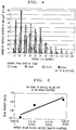
- FIG. 6 shows the mass spectrum of a particle composed of SiO2.
- FIG. 7 shows the mass spectrum of a particle composed of (NH4)2SO4.
- FIG. 8 shows the mass spectrum of particle composed of KCl and SiO2.
- a mobile particle analyzer 2 which detects, counts, size discriminates, and analyzes the chemical composition of particles suspended in air or process gases in real time.
- the apparatus 2 is comprised of an inlet device 3 through which the particles pass and enter into a differentially pumped chamber 6.
- a pulsed laser 10 is focused at an opening in the chamber 6.
- the opening in the chamber 6 can either be in line with the path traveled by the particles or perpendicular to the path traveled by the particles.
- a time of flight mass spectrometer (TOF/MS) 12 obtains the mass spectra created when particles come in contact with the laser beam.
- a transient recorder such as a digital oscilloscope 16 records the mass spectra and a computer 22 analyzes and displays the information received from the oscilloscope 16.
- a sample of gas enters into the apparatus 2 via an inlet device 3.
- the inlet device 3 can be a capillary 4, a capillary 4 with one or more pumped skimmers 24 positioned at the end of the capillary 4, or a pumped jet separator capillary 5, as shown in Figure 2.
- the pressure in the skimmers 24 or the jet separator capillary 5 is kept at approximately 0.01 - 1 torr by mechanical pumps 28.
- Use of skimmers 24 or a jet separator capillary 5 assist in the focusing of the gas sample into the chamber 6.
- the inlet device 3 is made from any material which provides a smooth and even inside diameter such as fused silica.
- the diameter and length of the inlet device 3 varies depending on a number of factors including the pressure in the differentially pumped chamber 6 located at the outlet end of the inlet device 3.
- the diameter of the inlet device 3 is 0.25-0.53 mm and is 50 cm long for particle sizes in the range of 0.01 to 1 micron and for a pressure in the chamber 6 of approximately 10 ⁇ 4 torr.
- the chamber 6 is kept at a pressure of approximately 10 ⁇ 4 torr by a diffusion pump 7 and mechanical pump 8 of a type well known in the art. Reducing the diameter of the inlet device 3, positioning one or more skimmers 24 at the end of the capillary 4 or using a jet separator capillary 5 are all methods of reducing the pressure in the differentially pumped chamber 6.
- the pressure in the chamber 6 needs to be kept low to enable the particle beam to move through the inlet device 3 into the chamber 6 and for the TOF/MS 12 to operate.
- a pulsed ionization laser 10 is focused on the particle beam after the beam leaves the inlet device 3.
- the optimum ionization laser 10 has a short pulse width, a high peak power, a moderate spot size and a high repetition rate. Each of these factors however are interrelated to each other and thus have corresponding effects on the other factors.
- the laser pulse width affects the mass resolution and signal intensity.
- a short laser pulse width of approximately 10 ns narrows the ion generation pulse, thereby improving mass resolution and increasing the signal intensity. Increased signal intensity allows detection of smaller particles.
- Laser power of approximately 0.5 mJ or greater with a power density of greater than 1.5x10⁸W/cm2 is required to initiate particle ablation and ionization. Lowering the laser power density to less than 1.5x10⁸W/cm2 typically results in unusually small signals from the particles. At or above 1.5x10⁸W/cm2 an ion signal from 1 to 3 volts is typically produced by particles of approximately one micron in size. Additionally, lowering the laser power, lowers the particle detection rate.
- a laser 10 having a pulse frequency of approximately 30 Hz such as a Lambda Physik excimer laser has a focus spot size of approximately 2 mm2.
- a laser 10 with a pulse frequency of approximately 2,000 Hz such as a TFR Spectra Physics laser has a focus spot size of approximately 0.1 mm2.
- a spot size of approximately 0.2 to 2 mm2 is optimum.
- a laser having a frequency between 1 - 10 kHz is preferred, however a frequency between 10 to 100 Hz is acceptable.
- Lasers which have the characteristics of a short pulse width, a high peak power density, a moderate spot size and a moderate repetition rate include an excimer laser.
- An example of such a laser is a Lambda Physik model EMG 202 excimer laser with a 40 ns pulse width, 2x10⁸W/cm2 peak power, 2 mm x 0.5 mm spot size and 1 - 50 Hz repetition rate.
- a dual positive and negative time of flight mass spectrometer (TOF/MS) 12 such as a Jordon Associates Dual TOF/MS is positioned in line with the focal point of the laser 10.
- the spectrometer 12 counts each fragmentation incident and measures the masses and yields of both positive and negative ions produced when the particle beam comes in contact with the laser beam.
- the mass of the particles is dependent on the time it takes for the particle fragments to come into contact with the TOF/MS.
- the ionic yield is dependent on the charge given off by the fragmented particles.
- the signal intensity and mass resolution of the ionized particles are improved by using a reflectron (not shown) in the spectrometer 12.
- the addition of a reflectron (not shown) narrows the peaks giving a better mass measurement and the peak intensity increases improving the detection limits.
- the output signal from the spectrometer 12 is recorded with a digital oscilloscope 16 such as a Tektronix 2440 or a Tektronix DSA 602.
- the digitized signal is analyzed and displayed with a computer 22 such as personal computer or a Macintosh.
- the computer takes the raw data and converts it into useable information relating to the chemical nature and concentration of the species in the particles, the chemical nature and concentration of the particles and the size of the particles. This information is then displayed in various formats.
- the operation of the analyzer 2 begins with a particle laden gas sample passing through the inlet device 3 into the differentially pumped chamber 6.
- the pressure level in the chamber 6 affects a number of factors including the rate of particles entering into the chamber 6, the amount of particle dispersion which occurs when the particle beam leaves the inlet device 3 and how close the laser 10 is focused to the end of the inlet device 3.
- Gas flow through the inlet device 3 into the chamber 6 is a factor which determines the rate of particle transport into the chamber and affects the particle detection rate.
- the gas flow through the inlet device 3 must be sufficient to enable the particles to enter into the chamber 6. Particles will not be transported and thus will not be detected if the gas flow is too low.
- the gas flow of a sample through the inlet device 3 is based on the diameter and length of the capillary 4 and the pressure in the chamber 6.
- An inlet device 3 having a diameter of 0.53 mm ID, a length of 50 cm and a differential pressure greater than seven hundred fifty in the chamber 6 has an air flow of approximately 8.1 cm3/sec.
- Figure 4 shows the relative particle density as a function of particle size and radial distance from the capillary center at a distance of 4.5 cm from the inlet device 3. This figure clearly shows that smaller particles are more easily carried by the expanding gas to a larger radius; they dominate at the fringes of the beam ( ⁇ 1.9 mm). On the other hand, large particles, greater than one micron, concentrate in the center of the particle beam ( ⁇ 1.9 mm).
- the size of the particles being detected can be pre-determined and selected.
- focusing the laser 10 at the center of the particle beam primarily larger particles are detected, whereas focusing the laser 10 at the fringes of the beam ( ⁇ 1.9 mm) smaller particles are detected.
- Optimum particle detection requires focusing the laser 10 immediately or in close proximity to the outlet end of the inlet device 3 to minimize effects of dispersion of the particle beam.
- An alternative is also to have the laser 10 scan the dispersion range of the particle beam to obtain a full spectrum of particles.
- the laser 10 Upon the introduction of a sample into the inlet device 3 the laser 10 is turned on and continuously fired.
- the power density of the laser is greater than 1.5X10⁸W/cm2. Because the laser 10 is continuously firing there is no need for a second laser to detect the particle beam and trigger the firing laser.
- the laser 10 is focused at a point where the particle beam leaves the inlet device 3. As the particle beam leaves the inlet device 3 it passes through the laser beam which fragments, atomizes and ionizes the particles.
- An ion signal or mass spectrum is produced when the particle beam comes in contact with the laser beam.
- the ion signal is detected and read by the spectrometer 12.
- the frequency of the fragmentation incidents determines the concentration of the particles in the gas sample.
- the ion masses characterize the chemical nature of the species contained in the particle.
- the ionic yield relates to the concentration of the species in the particle which was ionized.
- the combined yield of all the ions determines the size of the particle.
- the ion signal produced by the particles is a function of laser power density and particle size with a threshold dependence.
- the laser power density should be at or above 1.5x10⁸W/cm2 for ionization to occur.
- the ion signal produced by the particles is linear with the particle volume.
- Figure 4 shows the linear ion signal for particles between 0.01 - 0.025 micron. Particles generated by atomizing a 0.2 to 10 mM CsNO3 solution produced Cs+ signals with an intensity of 1.5 to 3 volts. Particles generated from a 0.004 mM CsNO3 solution gave weaker intensity Cs+ signals, 0.04 to 0.4 volts. Thus if the laser power density is not sufficient enough only the surface of particles rather than the whole particle is ionized.
- a synthetic dust sample having a composition of 66%Talc (4SiO2-3MgO-H2O), 29%(NH4)2SO4, 3%(NH4)HSO4, 1%KCL, and 1%NaHCO3 was passed through the laser beam.
- the mass spectra produced by this sample are shown in Figures 6 through 8. Each spectrum is the signal produced as a result of four laser pulses.
- the ions observed in the mass spectrum show that the particles in the sample are not a homogeneous representation of the solid mixture. The identity of the particles were assigned based upon the mass spectra obtained when the particles were ionized.
- Figure 6 shows silica without the magnesium present in talc
- Figure 7 is pure ammonium sulfate without the major constituent talc observed
- Figure 8 shows a mixture of silica and potassium chloride.
- Figure 8 results from the detection of two particles within one laser pulse or from two different pulses averaged together during the four laser pulse averaging time. There was a count rate of 1 - 2 particles per second detected. Consequently the concentration of the composition was 3 - 4 x 10¹⁰ particles per cubic foot as is determinable from Figure 3. From independent measurements the concentration of particles was determined to be approximately 5x 10¹⁰ particles per cubic foot. The size of the particles in the composition was determined as a result of the signal intensity which was produced when the particles were ionized. Referring to Figures 6 - 8 it is shown that the total ionic yield was approximately 7V. By extrapolation of the data in Figure 5 it was determined that the particles had a diameter of approximately 0.03 micron.
Landscapes
- Chemical & Material Sciences (AREA)
- Analytical Chemistry (AREA)
- Physics & Mathematics (AREA)
- Optics & Photonics (AREA)
- Engineering & Computer Science (AREA)
- Plasma & Fusion (AREA)
- Other Investigation Or Analysis Of Materials By Electrical Means (AREA)
- Electron Tubes For Measurement (AREA)
Applications Claiming Priority (2)
| Application Number | Priority Date | Filing Date | Title |
|---|---|---|---|
| US94413392A | 1992-09-11 | 1992-09-11 | |
| US944133 | 1992-09-11 |
Publications (3)
| Publication Number | Publication Date |
|---|---|
| EP0587369A2 true EP0587369A2 (fr) | 1994-03-16 |
| EP0587369A3 EP0587369A3 (en) | 1995-08-16 |
| EP0587369B1 EP0587369B1 (fr) | 1998-02-04 |
Family
ID=25480851
Family Applications (1)
| Application Number | Title | Priority Date | Filing Date |
|---|---|---|---|
| EP93306918A Expired - Lifetime EP0587369B1 (fr) | 1992-09-11 | 1993-09-01 | Dispositif comprenant un spectromètre de mosse |
Country Status (5)
| Country | Link |
|---|---|
| US (1) | US5382794A (fr) |
| EP (1) | EP0587369B1 (fr) |
| JP (1) | JP3445323B2 (fr) |
| CA (1) | CA2101237C (fr) |
| DE (1) | DE69316807T2 (fr) |
Cited By (1)
| Publication number | Priority date | Publication date | Assignee | Title |
|---|---|---|---|---|
| EP0723282A1 (fr) * | 1995-01-17 | 1996-07-24 | AT&T Corp. | Analyse de particules assistée par laser |
Families Citing this family (24)
| Publication number | Priority date | Publication date | Assignee | Title |
|---|---|---|---|---|
| GB9324213D0 (en) * | 1993-11-25 | 1994-01-12 | Kore Tech Ltd | Vacuum inlet |
| US5998215A (en) * | 1995-05-01 | 1999-12-07 | The Regents Of The University Of California | Portable analyzer for determining size and chemical composition of an aerosol |
| US5788166A (en) * | 1996-08-27 | 1998-08-04 | Cornell Research Foundation, Inc. | Electrospray ionization source and method of using the same |
| US5977541A (en) * | 1996-08-29 | 1999-11-02 | Nkk Corporation | Laser ionization mass spectroscope and mass spectrometric analysis method |
| DE19734460A1 (de) * | 1997-08-11 | 1999-02-18 | Gsf Forschungszentrum Umwelt | Verfahren und Vorrichtung zum analytischen Nachweis von Spuren |
| US6259101B1 (en) * | 1997-09-23 | 2001-07-10 | University Of Delaware | Method and instruments for the on-line detection, sizing or analysis of aerosol particles |
| US6040574A (en) * | 1998-03-05 | 2000-03-21 | Aerodyne Research, Inc. | Atmospheric-particle analyzer |
| US5977540A (en) * | 1998-04-16 | 1999-11-02 | Lucent Technologies Inc. | Laser-assisted particle analysis |
| EP1166085A2 (fr) * | 1999-02-25 | 2002-01-02 | Clemson University Research Foundation | Echantillonnage et analyse de matiere particulaire portee par l'air a l'aide d'une emission atomique a decharge incandescente et de spectrometries de masse |
| US6633032B2 (en) * | 2000-11-30 | 2003-10-14 | Agere Systems Inc. | Mass spectrometer particle counter |
| US6777673B2 (en) | 2001-12-28 | 2004-08-17 | Academia Sinica | Ion trap mass spectrometer |
| US6784423B2 (en) * | 2002-09-20 | 2004-08-31 | Lucent Technologies Inc. | Characterization of individual particle atomic composition by aerosol mass spectrometry |
| US6974957B2 (en) * | 2004-02-18 | 2005-12-13 | Nanomat, Inc. | Ionization device for aerosol mass spectrometer and method of ionization |
| FI20050385A0 (fi) * | 2005-04-14 | 2005-04-14 | Jukka Rantanen | Menetelmä ja laitteisto kiinteän aineen liuottamiseksi nesteeseen |
| US8648294B2 (en) | 2006-10-17 | 2014-02-11 | The Regents Of The University Of California | Compact aerosol time-of-flight mass spectrometer |
| JP5024375B2 (ja) * | 2007-05-30 | 2012-09-12 | 株式会社島津製作所 | 質量分析装置 |
| US9285298B2 (en) * | 2010-03-17 | 2016-03-15 | The University Of Tokyo | Method of analyzing microparticle composition and microparticle composition analyzing device |
| EP2698621A1 (fr) * | 2012-08-14 | 2014-02-19 | Tofwerk AG | Procédé et appareil permettant de déterminer la taille des particules d'aérosol |
| EP2927666A4 (fr) * | 2012-12-03 | 2016-08-03 | Fuji Electric Co Ltd | Dispositif de formation de faisceau de particules |
| US9536725B2 (en) | 2013-02-05 | 2017-01-03 | Clemson University | Means of introducing an analyte into liquid sampling atmospheric pressure glow discharge |
| CN107703204B (zh) * | 2017-09-26 | 2021-09-14 | 中国检验检疫科学研究院 | 一种杀虫剂产品中禁用农药的快速检测方法 |
| US11996280B2 (en) * | 2019-06-29 | 2024-05-28 | Zeteo Tech, Inc. | Methods and systems for detecting aerosol particles without using complex organic MALDI matrices |
| CN113218846A (zh) * | 2021-03-18 | 2021-08-06 | 上海交通大学 | 一种面向于单细胞质谱流式分析的icp装置 |
| CN116072506B (zh) * | 2023-01-06 | 2024-06-25 | 西北核技术研究所 | 颗粒物进样装置、气溶胶质谱仪、单颗粒直径测量方法 |
Family Cites Families (5)
| Publication number | Priority date | Publication date | Assignee | Title |
|---|---|---|---|---|
| US4383171A (en) * | 1980-11-17 | 1983-05-10 | The United States Of America As Represented By The Administrator Of The National Aeronautics And Space Administration | Particle analyzing method and apparatus |
| US4733073A (en) * | 1983-12-23 | 1988-03-22 | Sri International | Method and apparatus for surface diagnostics |
| DE3517667A1 (de) * | 1985-05-15 | 1986-11-20 | Max-Planck-Gesellschaft zur Förderung der Wissenschaften e.V., 3400 Göttingen | Laser-massenspektrometer |
| US4855594A (en) * | 1988-03-02 | 1989-08-08 | Air Products And Chemicals, Inc. | Apparatus and process for improved detection limits in mass spectrometry |
| DE3842044A1 (de) * | 1988-12-14 | 1990-06-21 | Forschungszentrum Juelich Gmbh | Flugzeit(massen)spektrometer mit hoher aufloesung und transmission |
-
1993
- 1993-07-23 CA CA002101237A patent/CA2101237C/fr not_active Expired - Fee Related
- 1993-09-01 EP EP93306918A patent/EP0587369B1/fr not_active Expired - Lifetime
- 1993-09-01 DE DE69316807T patent/DE69316807T2/de not_active Expired - Lifetime
- 1993-09-10 JP JP22548993A patent/JP3445323B2/ja not_active Expired - Fee Related
- 1993-12-29 US US08/175,164 patent/US5382794A/en not_active Expired - Lifetime
Cited By (1)
| Publication number | Priority date | Publication date | Assignee | Title |
|---|---|---|---|---|
| EP0723282A1 (fr) * | 1995-01-17 | 1996-07-24 | AT&T Corp. | Analyse de particules assistée par laser |
Also Published As
| Publication number | Publication date |
|---|---|
| EP0587369A3 (en) | 1995-08-16 |
| CA2101237C (fr) | 1999-04-13 |
| JPH06201567A (ja) | 1994-07-19 |
| DE69316807D1 (de) | 1998-03-12 |
| DE69316807T2 (de) | 1998-05-28 |
| US5382794A (en) | 1995-01-17 |
| JP3445323B2 (ja) | 2003-09-08 |
| CA2101237A1 (fr) | 1994-03-12 |
| EP0587369B1 (fr) | 1998-02-04 |
Similar Documents
| Publication | Publication Date | Title |
|---|---|---|
| EP0587369B1 (fr) | Dispositif comprenant un spectromètre de mosse | |
| US4968885A (en) | Method and apparatus for introduction of liquid effluent into mass spectrometer and other gas-phase or particle detectors | |
| Noble et al. | Real‐time single particle mass spectrometry: A historical review of a quarter century of the chemical analysis of aerosols | |
| US4733073A (en) | Method and apparatus for surface diagnostics | |
| Hinz et al. | Laser-induced mass analysis of single particles in the airborne state | |
| Morrical et al. | Coupling two-step laser desorption/ionization with aerosol time-of-flight mass spectrometry for the analysis of individual organic particles | |
| US5681752A (en) | Method and apparatus for determining the size and chemical composition of aerosol particles | |
| US5285064A (en) | Method and apparatus for introduction of liquid effluent into mass spectrometer and other gas-phase or particle detectors | |
| EP1060380B1 (fr) | Analyseur de particules atmospheriques | |
| JP2002141017A (ja) | イオン移動度スペクトロメータ | |
| US5631462A (en) | Laser-assisted particle analysis | |
| US6180941B1 (en) | Mass spectrometer | |
| Weiss et al. | On the performance of an on-line time-of-flight mass spectrometer for aerosols | |
| Yang et al. | Real‐time chemical analysis of aerosol particles using an ion trap mass spectrometer | |
| EP0418785B1 (fr) | Méthode et dispositif pour l'analyse par spectrométrie de masse | |
| JP2003536209A (ja) | 携帯飛行時間型質量分析システム | |
| Nakazato et al. | Elemental and isotopic analyses of individual nanoparticles using single particle inductively coupled plasma mass spectrometry: M. Nakazato, T. Hirata | |
| US5977540A (en) | Laser-assisted particle analysis | |
| EP0167561B1 (fr) | Procede et dispositif de diagnostic de surface | |
| WO1996031900A1 (fr) | Procede et dispositif d'analyse de la composition chimique de particules | |
| Coggiola et al. | Airborne deployment of an instrument for the real-time analysis of single aerosol particles | |
| RU2059982C1 (ru) | Времяпролетный масс-спектрометр и способ масс-спектрометрического анализа вещества | |
| Sinha | Characterization of individual particles in gaseous media by mass spectrometry | |
| JP2941762B2 (ja) | ダイオキシン分析装置 | |
| CA2167099A1 (fr) | Analyse des particules en suspension dans des echantillons de fluide |
Legal Events
| Date | Code | Title | Description |
|---|---|---|---|
| PUAI | Public reference made under article 153(3) epc to a published international application that has entered the european phase |
Free format text: ORIGINAL CODE: 0009012 |
|
| AK | Designated contracting states |
Kind code of ref document: A2 Designated state(s): DE FR GB |
|
| RAP3 | Party data changed (applicant data changed or rights of an application transferred) |
Owner name: AT&T CORP. |
|
| PUAL | Search report despatched |
Free format text: ORIGINAL CODE: 0009013 |
|
| AK | Designated contracting states |
Kind code of ref document: A3 Designated state(s): DE FR GB |
|
| 17P | Request for examination filed |
Effective date: 19960131 |
|
| 17Q | First examination report despatched |
Effective date: 19960618 |
|
| GRAG | Despatch of communication of intention to grant |
Free format text: ORIGINAL CODE: EPIDOS AGRA |
|
| GRAG | Despatch of communication of intention to grant |
Free format text: ORIGINAL CODE: EPIDOS AGRA |
|
| GRAH | Despatch of communication of intention to grant a patent |
Free format text: ORIGINAL CODE: EPIDOS IGRA |
|
| GRAH | Despatch of communication of intention to grant a patent |
Free format text: ORIGINAL CODE: EPIDOS IGRA |
|
| GRAA | (expected) grant |
Free format text: ORIGINAL CODE: 0009210 |
|
| AK | Designated contracting states |
Kind code of ref document: B1 Designated state(s): DE FR GB |
|
| ET | Fr: translation filed | ||
| REF | Corresponds to: |
Ref document number: 69316807 Country of ref document: DE Date of ref document: 19980312 |
|
| PLBE | No opposition filed within time limit |
Free format text: ORIGINAL CODE: 0009261 |
|
| STAA | Information on the status of an ep patent application or granted ep patent |
Free format text: STATUS: NO OPPOSITION FILED WITHIN TIME LIMIT |
|
| 26N | No opposition filed | ||
| PGFP | Annual fee paid to national office [announced via postgrant information from national office to epo] |
Ref country code: FR Payment date: 20010823 Year of fee payment: 9 |
|
| PGFP | Annual fee paid to national office [announced via postgrant information from national office to epo] |
Ref country code: GB Payment date: 20010828 Year of fee payment: 9 |
|
| REG | Reference to a national code |
Ref country code: GB Ref legal event code: IF02 |
|
| PG25 | Lapsed in a contracting state [announced via postgrant information from national office to epo] |
Ref country code: GB Free format text: LAPSE BECAUSE OF NON-PAYMENT OF DUE FEES Effective date: 20020901 |
|
| GBPC | Gb: european patent ceased through non-payment of renewal fee |
Effective date: 20020901 |
|
| PG25 | Lapsed in a contracting state [announced via postgrant information from national office to epo] |
Ref country code: FR Free format text: LAPSE BECAUSE OF NON-PAYMENT OF DUE FEES Effective date: 20030603 |
|
| REG | Reference to a national code |
Ref country code: FR Ref legal event code: ST |
|
| PGFP | Annual fee paid to national office [announced via postgrant information from national office to epo] |
Ref country code: DE Payment date: 20090922 Year of fee payment: 17 |
|
| REG | Reference to a national code |
Ref country code: DE Ref legal event code: R119 Ref document number: 69316807 Country of ref document: DE Effective date: 20110401 |
|
| PG25 | Lapsed in a contracting state [announced via postgrant information from national office to epo] |
Ref country code: DE Free format text: LAPSE BECAUSE OF NON-PAYMENT OF DUE FEES Effective date: 20110401 |