EP0587553A1 - Dispositif pour introduire du gaz dans des liquides - Google Patents
Dispositif pour introduire du gaz dans des liquides Download PDFInfo
- Publication number
- EP0587553A1 EP0587553A1 EP93890164A EP93890164A EP0587553A1 EP 0587553 A1 EP0587553 A1 EP 0587553A1 EP 93890164 A EP93890164 A EP 93890164A EP 93890164 A EP93890164 A EP 93890164A EP 0587553 A1 EP0587553 A1 EP 0587553A1
- Authority
- EP
- European Patent Office
- Prior art keywords
- gas
- distributor
- liquid
- pipes
- over
- Prior art date
- Legal status (The legal status is an assumption and is not a legal conclusion. Google has not performed a legal analysis and makes no representation as to the accuracy of the status listed.)
- Granted
Links
- 239000007788 liquid Substances 0.000 title claims abstract description 25
- 239000000203 mixture Substances 0.000 claims abstract description 19
- 230000032258 transport Effects 0.000 abstract 1
- 239000007789 gas Substances 0.000 description 55
- QVGXLLKOCUKJST-UHFFFAOYSA-N atomic oxygen Chemical compound [O] QVGXLLKOCUKJST-UHFFFAOYSA-N 0.000 description 11
- 239000001301 oxygen Substances 0.000 description 11
- 229910052760 oxygen Inorganic materials 0.000 description 11
- 238000005276 aerator Methods 0.000 description 4
- XLYOFNOQVPJJNP-UHFFFAOYSA-N water Substances O XLYOFNOQVPJJNP-UHFFFAOYSA-N 0.000 description 4
- 238000009434 installation Methods 0.000 description 3
- 230000007423 decrease Effects 0.000 description 2
- 230000000694 effects Effects 0.000 description 2
- 238000007654 immersion Methods 0.000 description 2
- 230000000630 rising effect Effects 0.000 description 2
- 238000005273 aeration Methods 0.000 description 1
- 230000001174 ascending effect Effects 0.000 description 1
- 238000010276 construction Methods 0.000 description 1
- 230000007812 deficiency Effects 0.000 description 1
- 238000007142 ring opening reaction Methods 0.000 description 1
- 239000002351 wastewater Substances 0.000 description 1
Images
Classifications
-
- C—CHEMISTRY; METALLURGY
- C02—TREATMENT OF WATER, WASTE WATER, SEWAGE, OR SLUDGE
- C02F—TREATMENT OF WATER, WASTE WATER, SEWAGE, OR SLUDGE
- C02F1/00—Treatment of water, waste water, or sewage
- C02F1/72—Treatment of water, waste water, or sewage by oxidation
- C02F1/74—Treatment of water, waste water, or sewage by oxidation with air
-
- B—PERFORMING OPERATIONS; TRANSPORTING
- B01—PHYSICAL OR CHEMICAL PROCESSES OR APPARATUS IN GENERAL
- B01F—MIXING, e.g. DISSOLVING, EMULSIFYING OR DISPERSING
- B01F23/00—Mixing according to the phases to be mixed, e.g. dispersing or emulsifying
- B01F23/20—Mixing gases with liquids
- B01F23/23—Mixing gases with liquids by introducing gases into liquid media, e.g. for producing aerated liquids
- B01F23/233—Mixing gases with liquids by introducing gases into liquid media, e.g. for producing aerated liquids using driven stirrers with completely immersed stirring elements
- B01F23/2334—Mixing gases with liquids by introducing gases into liquid media, e.g. for producing aerated liquids using driven stirrers with completely immersed stirring elements provided with stationary guiding means surrounding at least partially the stirrer
- B01F23/23342—Mixing gases with liquids by introducing gases into liquid media, e.g. for producing aerated liquids using driven stirrers with completely immersed stirring elements provided with stationary guiding means surrounding at least partially the stirrer the stirrer being of the centrifugal type, e.g. with a surrounding stator
-
- B—PERFORMING OPERATIONS; TRANSPORTING
- B01—PHYSICAL OR CHEMICAL PROCESSES OR APPARATUS IN GENERAL
- B01F—MIXING, e.g. DISSOLVING, EMULSIFYING OR DISPERSING
- B01F23/00—Mixing according to the phases to be mixed, e.g. dispersing or emulsifying
- B01F23/20—Mixing gases with liquids
- B01F23/23—Mixing gases with liquids by introducing gases into liquid media, e.g. for producing aerated liquids
-
- B—PERFORMING OPERATIONS; TRANSPORTING
- B01—PHYSICAL OR CHEMICAL PROCESSES OR APPARATUS IN GENERAL
- B01F—MIXING, e.g. DISSOLVING, EMULSIFYING OR DISPERSING
- B01F23/00—Mixing according to the phases to be mixed, e.g. dispersing or emulsifying
- B01F23/40—Mixing liquids with liquids; Emulsifying
- B01F23/45—Mixing liquids with liquids; Emulsifying using flow mixing
- B01F23/454—Mixing liquids with liquids; Emulsifying using flow mixing by injecting a mixture of liquid and gas
-
- B—PERFORMING OPERATIONS; TRANSPORTING
- B01—PHYSICAL OR CHEMICAL PROCESSES OR APPARATUS IN GENERAL
- B01F—MIXING, e.g. DISSOLVING, EMULSIFYING OR DISPERSING
- B01F25/00—Flow mixers; Mixers for falling materials, e.g. solid particles
- B01F25/20—Jet mixers, i.e. mixers using high-speed fluid streams
- B01F25/21—Jet mixers, i.e. mixers using high-speed fluid streams with submerged injectors, e.g. nozzles, for injecting high-pressure jets into a large volume or into mixing chambers
-
- B—PERFORMING OPERATIONS; TRANSPORTING
- B01—PHYSICAL OR CHEMICAL PROCESSES OR APPARATUS IN GENERAL
- B01F—MIXING, e.g. DISSOLVING, EMULSIFYING OR DISPERSING
- B01F27/00—Mixers with rotary stirring devices in fixed receptacles; Kneaders
- B01F27/25—Mixers with both stirrer and drive unit submerged in the material being mixed
-
- B—PERFORMING OPERATIONS; TRANSPORTING
- B01—PHYSICAL OR CHEMICAL PROCESSES OR APPARATUS IN GENERAL
- B01F—MIXING, e.g. DISSOLVING, EMULSIFYING OR DISPERSING
- B01F23/00—Mixing according to the phases to be mixed, e.g. dispersing or emulsifying
- B01F23/20—Mixing gases with liquids
- B01F23/23—Mixing gases with liquids by introducing gases into liquid media, e.g. for producing aerated liquids
- B01F23/233—Mixing gases with liquids by introducing gases into liquid media, e.g. for producing aerated liquids using driven stirrers with completely immersed stirring elements
- B01F23/2335—Mixing gases with liquids by introducing gases into liquid media, e.g. for producing aerated liquids using driven stirrers with completely immersed stirring elements characterised by the direction of introduction of the gas relative to the stirrer
- B01F23/23352—Mixing gases with liquids by introducing gases into liquid media, e.g. for producing aerated liquids using driven stirrers with completely immersed stirring elements characterised by the direction of introduction of the gas relative to the stirrer the gas moving perpendicular to the axis of rotation
-
- B—PERFORMING OPERATIONS; TRANSPORTING
- B01—PHYSICAL OR CHEMICAL PROCESSES OR APPARATUS IN GENERAL
- B01F—MIXING, e.g. DISSOLVING, EMULSIFYING OR DISPERSING
- B01F23/00—Mixing according to the phases to be mixed, e.g. dispersing or emulsifying
- B01F23/20—Mixing gases with liquids
- B01F23/23—Mixing gases with liquids by introducing gases into liquid media, e.g. for producing aerated liquids
- B01F23/233—Mixing gases with liquids by introducing gases into liquid media, e.g. for producing aerated liquids using driven stirrers with completely immersed stirring elements
- B01F23/2335—Mixing gases with liquids by introducing gases into liquid media, e.g. for producing aerated liquids using driven stirrers with completely immersed stirring elements characterised by the direction of introduction of the gas relative to the stirrer
- B01F23/23353—Mixing gases with liquids by introducing gases into liquid media, e.g. for producing aerated liquids using driven stirrers with completely immersed stirring elements characterised by the direction of introduction of the gas relative to the stirrer the gas being sucked towards the rotating stirrer
-
- B—PERFORMING OPERATIONS; TRANSPORTING
- B01—PHYSICAL OR CHEMICAL PROCESSES OR APPARATUS IN GENERAL
- B01F—MIXING, e.g. DISSOLVING, EMULSIFYING OR DISPERSING
- B01F23/00—Mixing according to the phases to be mixed, e.g. dispersing or emulsifying
- B01F23/20—Mixing gases with liquids
- B01F23/23—Mixing gases with liquids by introducing gases into liquid media, e.g. for producing aerated liquids
- B01F23/233—Mixing gases with liquids by introducing gases into liquid media, e.g. for producing aerated liquids using driven stirrers with completely immersed stirring elements
- B01F23/2336—Mixing gases with liquids by introducing gases into liquid media, e.g. for producing aerated liquids using driven stirrers with completely immersed stirring elements characterised by the location of the place of introduction of the gas relative to the stirrer
- B01F23/23362—Mixing gases with liquids by introducing gases into liquid media, e.g. for producing aerated liquids using driven stirrers with completely immersed stirring elements characterised by the location of the place of introduction of the gas relative to the stirrer the gas being introduced under the stirrer
Definitions
- the invention relates to a device for introducing gas into liquids, consisting of a gas and liquid-conveying rotor arranged in the bottom region of a container with a vertical axis of rotation and a stator surrounding the rotor, to which distribution pipes for the liquid-gas mixture distributed over the circumference are connected are.
- FR-B-2 444 494 serves the same purpose, in which the stator is designed as a mixing chamber for the air supplied to the rotor blades and the sucked-in liquid, distribution pipes for the liquid being distributed over the circumference to the mixing chamber. Connect the air mixture, which in turn is to ensure a greater discharge range of the liquid-air mixture.
- a disadvantage of these known devices is, however, that the length of the distribution pipes can not be increased arbitrarily, because with increasing pipe length, the risk increases that the fine gas bubbles of the liquid-gas mixture in the distribution pipes combine to form larger gas bubbles, so that the desired fine distribution of the gas bubbles over the Base area of the proposed gas entry area is no longer given.
- the invention is therefore based on the object to avoid these deficiencies and to improve a device for gas introduction into liquids described above with simple constructional means so that the base area for a uniform gas entry area can be increased considerably.
- the invention achieves the stated object in that the distributor pipes, which extend at least essentially over the base area of the gas introduction region, have distributor openings which are directed upwards over their entire length.
- the provision of upward-pointing distributor openings in the distributor pipes allows part of the liquid-gas mixture to escape into the liquid distributed over the pipe length, which on the one hand ensures a corresponding distribution of the gas bubbles over the radial extent of the distributor pipes and on the other hand unites the gas bubbles into larger ones Prevents gas bubbles within the distribution pipes because the fine gas bubbles cannot collect in the upper wall area of the distribution pipes.
- the base area for the possible gas entry area can therefore be increased considerably without the to have to accept the otherwise occurring disadvantages. This applies regardless of the rotor or stator version.
- the stator can accordingly be designed both as a guide device for the liquid-gas mixture expelled by the rotor and as a mixing chamber.
- the delivery pressure along the distributor pipes decreases accordingly.
- the passage cross section of the distributor openings can increase over the pipe length towards the outlet end of the pipes in a further development of the invention, which leads to a more uniform gas introduction over the radial extension area of the distributor pipes .
- the distributor openings can be designed differently and, for example, consist of rows of holes on the top of the distributor pipes. Particularly simple construction conditions result, however, if the distributor openings consist of a longitudinal slot provided on the upper side of the distributor pipes, through which a portion of the liquid-gas mixture can escape continuously over the pipe length. In such a case, the slot width only needs to take the pressure drop into account increase towards the outlet end of the pipe.
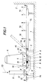
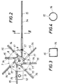
- the device for introducing gas into liquids essentially consists of a frame 3 provided on the bottom 1 of a basin-shaped container 2, which supports a motor 4 with a shaft 5 for driving a rotor 6, and a stator surrounding the rotor 6 7, which forms flow channels 9 between two annular disks 8, the axes of which are inclined in the direction of rotation of the rotor with respect to the associated radial, as shown in FIG. 2.
- distributor pipes 14 are connected to the flow channels 9 of the stator 7, which have distributor openings 15 in the form of a longitudinal slot on their upper side, so that the liquid-gas mixture emerging from the flow channels 9 within the distributor pipes 14 continuing the flow channels 9 is forwarded, with a portion of the liquid-gas mixture constantly emerging upward along the distributor pipes 14 into the container liquid, as is indicated by the arrows 16 in FIG. 1.
- the width of the distributor openings 15 will generally be less than 50% of the pipe width and should preferably be chosen between 3 and 30 mm. A widening of the longitudinal slot 15 towards the outlet end of the distributor pipes is recommended if the pressure drop in the distributor pipes, which increases with the flow path, is to be taken into account.
- the distributor pipes 14 are pivoted upward about horizontal transverse axes 17 on the stator 7, as is indicated by the dash-dotted pivot position in FIG. 1.
- This articulation of the distributor pipes 14 on the stator 7 permits the installation of the device with swiveled-up distributor pipes, which are only pivoted into the position of use parallel to the floor after the device has been introduced into the basin 2.
- a cylindrical test tank with a diameter of 3.8 m was filled with pure water, the liquid height being 4 m.
- a self-priming immersion aerator was used, the stator of which had an outer diameter of 500 mm and eight flow channels with a length of 150 mm and a square cross section with a side length of 34 mm.
- 3.07 kg 02 / h could be introduced into the pure water, with an oxygen utilization of 27.1%.
- the footprint of the gas entry area was smaller than the bottom of the test tank.
- distributor pipes with a square cross-section were attached to the flow channels of the stator, their length was 1300 mm and they had a 3 mm wide longitudinal slot extending over the entire pipe length, an oxygen entry of 3.86 kg could be achieved under otherwise identical conditions 02 / h and an oxygen utilization of 34% are measured, which corresponds to an increase in the oxygen input performance by 25.7%.
- the effect of the measures according to the invention was also checked in a container with a floor area of 10 ⁇ 10 m, specifically at a water height of 4.10 m.
- the correspondingly larger immersion aerator used had an intake capacity of 200 m3 / h air.
- the stator whose outer diameter was 720 mm, was provided with 16 flow channels with a cross section of 34 x 34 mm. Without manifolds, only a base area with a diameter of approx. 4 m could be determined for the gas entry area.
- the oxygen input was determined in this arrangement with 10.67 kg 02 / h, the oxygen utilization with 17.9%.
- this submersible aerator was provided with manifolds each 3 m long and with a slot width of 4 mm, it was possible to achieve a uniform air entry over a base area with a diameter of approx. 7 m, with an oxygen entry of 13.48 kg 02 / h below an oxygen utilization of 22.5%.
- the slot width of the distributor pipes was widened from 1 mm in the area of the stator to 4 mm in the area of the outlet end.
- a further improvement in the distribution of the carried in air bubbles could be achieved, which was reflected in an oxygen input of 15.2 kg 02 / h with an oxygen utilization of 25.5%.
- the invention is of course not limited to the illustrated embodiment and can be used regardless of the shape and size of the container or the structural design of the gas introduction device.
- the gas to be introduced can be supplied to the rotor under pressure or a self-priming rotor can be used.
- the device according to the invention is particularly suitable for aeration of waste water. can of course be used anywhere there, where it is important to ensure even gas entry into a liquid over a larger area.
Landscapes
- Chemical & Material Sciences (AREA)
- Chemical Kinetics & Catalysis (AREA)
- Life Sciences & Earth Sciences (AREA)
- Hydrology & Water Resources (AREA)
- Engineering & Computer Science (AREA)
- Environmental & Geological Engineering (AREA)
- Water Supply & Treatment (AREA)
- Organic Chemistry (AREA)
- Aeration Devices For Treatment Of Activated Polluted Sludge (AREA)
- Nozzles (AREA)
- Jet Pumps And Other Pumps (AREA)
- Mixers Of The Rotary Stirring Type (AREA)
- Centrifugal Separators (AREA)
Applications Claiming Priority (2)
| Application Number | Priority Date | Filing Date | Title |
|---|---|---|---|
| AT1804/92 | 1992-09-10 | ||
| AT0180492A AT398046B (de) | 1992-09-10 | 1992-09-10 | Vorrichtung zur gaseintragung in flüssigkeiten |
Publications (2)
| Publication Number | Publication Date |
|---|---|
| EP0587553A1 true EP0587553A1 (fr) | 1994-03-16 |
| EP0587553B1 EP0587553B1 (fr) | 1997-01-15 |
Family
ID=3521337
Family Applications (1)
| Application Number | Title | Priority Date | Filing Date |
|---|---|---|---|
| EP93890164A Expired - Lifetime EP0587553B1 (fr) | 1992-09-10 | 1993-08-25 | Dispositif pour introduire du gaz dans des liquides |
Country Status (12)
| Country | Link |
|---|---|
| US (1) | US5356570A (fr) |
| EP (1) | EP0587553B1 (fr) |
| JP (1) | JPH0741264B2 (fr) |
| KR (1) | KR940006930A (fr) |
| AR (1) | AR247676A1 (fr) |
| AT (1) | AT398046B (fr) |
| BR (1) | BR9303749A (fr) |
| CA (1) | CA2105808C (fr) |
| DE (1) | DE59305126D1 (fr) |
| ES (1) | ES2097485T3 (fr) |
| FI (1) | FI103646B1 (fr) |
| MX (1) | MX9305555A (fr) |
Cited By (1)
| Publication number | Priority date | Publication date | Assignee | Title |
|---|---|---|---|---|
| EP0645177A1 (fr) * | 1993-09-29 | 1995-03-29 | Heinrich Frings GmbH & Co. KG | Dispositif pour l'introduction d'un gaz dans un liquide |
Families Citing this family (7)
| Publication number | Priority date | Publication date | Assignee | Title |
|---|---|---|---|---|
| DE19541436C2 (de) * | 1995-11-07 | 1998-10-08 | Steag Micro Tech Gmbh | Anlage zur Behandlung von Gegenständen in einem Prozeßtank |
| US5762833A (en) * | 1996-09-09 | 1998-06-09 | Aeromix Systems, Inc. | Aerator with a removable stator and method of repairing the same |
| US6395175B1 (en) | 2000-04-03 | 2002-05-28 | Battelle Memorial Institute | Method and apparatus for energy efficient self-aeration in chemical, biochemical, and wastewater treatment processes |
| JP5132243B2 (ja) * | 2007-10-17 | 2013-01-30 | 株式会社鶴見製作所 | 水中曝気装置 |
| US20110156290A1 (en) * | 2009-12-30 | 2011-06-30 | David Allen Wensloff | Medium Orbital Flow Oxygenator |
| KR101641432B1 (ko) | 2014-12-03 | 2016-07-21 | 연세대학교 산학협력단 | 무통 주사기 |
| ES2716153T3 (es) * | 2015-10-19 | 2019-06-10 | Nestec Sa | Aparato y método para la aireación de un producto alimenticio |
Citations (6)
| Publication number | Priority date | Publication date | Assignee | Title |
|---|---|---|---|---|
| US1768957A (en) * | 1929-01-07 | 1930-07-01 | Turbo Mixer Corp | Mixing or emulsifying apparatus |
| FR2129106A6 (en) * | 1971-03-11 | 1972-10-27 | Joncour Jean | Centrifugal turbine aerator - for treatment of waste water modified to improve air/water contact |
| FR2411159A1 (fr) * | 1977-12-06 | 1979-07-06 | Jeumont Schneider | Systeme d'injection de gaz dans un liquide |
| EP0089466A1 (fr) * | 1982-03-22 | 1983-09-28 | BLUM, Albert | Aérateur immergé |
| US4551285A (en) * | 1984-02-09 | 1985-11-05 | Envirotech Corporation | Flotation machine and aeration impeller |
| US4645603A (en) * | 1977-11-09 | 1987-02-24 | Frankl Gerald P | Liquid aeration device and method |
Family Cites Families (11)
| Publication number | Priority date | Publication date | Assignee | Title |
|---|---|---|---|---|
| US2138349A (en) * | 1936-02-10 | 1938-11-29 | Edward B Mallory | Method and apparatus for aerating sewage |
| US2458061A (en) * | 1947-07-12 | 1949-01-04 | Dorr Co | Slurry mixer |
| US2767965A (en) * | 1950-11-03 | 1956-10-23 | Mining Process & Patent Co | Dual pumping agitation |
| US2767964A (en) * | 1954-03-11 | 1956-10-23 | Galigher Company | Impeller-stator combination for flotation machines |
| DE1584885A1 (de) * | 1965-09-14 | 1970-02-05 | Danjes Dipl Ing Martin | Vorrichtung zum biologischen Reinigen von Abwaessern |
| US3911064A (en) * | 1971-04-08 | 1975-10-07 | Union Carbide Corp | System for gas sparging into liquid |
| NL7310255A (fr) * | 1972-09-01 | 1974-03-05 | ||
| FR2444494A1 (fr) * | 1978-12-21 | 1980-07-18 | Jeumont Schneider | Dispositif permettant de dissoudre et/ou de melanger un fluide dans un liquide, et pouvant etre notamment utilise pour l'aeration des eaux residuaires |
| DE3210473C2 (de) * | 1982-03-22 | 1985-02-21 | Blum, Albert, 5204 Lohmar | Tauchbelüfter |
| AT383108B (de) * | 1985-06-05 | 1987-05-25 | Frings & Co Heinrich | Belueftungsvorrichtung fuer fluessigkeiten |
| FI81077C (fi) * | 1987-06-11 | 1990-09-10 | Outokumpu Oy | Luftningsanordning foer avfallsvatten fraon industri och bebyggelse. |
-
1992
- 1992-09-10 AT AT0180492A patent/AT398046B/de not_active IP Right Cessation
-
1993
- 1993-08-25 ES ES93890164T patent/ES2097485T3/es not_active Expired - Lifetime
- 1993-08-25 EP EP93890164A patent/EP0587553B1/fr not_active Expired - Lifetime
- 1993-08-25 DE DE59305126T patent/DE59305126D1/de not_active Expired - Lifetime
- 1993-09-08 FI FI933932A patent/FI103646B1/fi not_active IP Right Cessation
- 1993-09-09 CA CA002105808A patent/CA2105808C/fr not_active Expired - Fee Related
- 1993-09-09 AR AR93325967A patent/AR247676A1/es active
- 1993-09-09 BR BR9303749A patent/BR9303749A/pt not_active IP Right Cessation
- 1993-09-10 KR KR1019930018164A patent/KR940006930A/ko not_active Withdrawn
- 1993-09-10 US US08/120,005 patent/US5356570A/en not_active Expired - Lifetime
- 1993-09-10 MX MX9305555A patent/MX9305555A/es not_active IP Right Cessation
- 1993-09-10 JP JP5225783A patent/JPH0741264B2/ja not_active Expired - Fee Related
Patent Citations (6)
| Publication number | Priority date | Publication date | Assignee | Title |
|---|---|---|---|---|
| US1768957A (en) * | 1929-01-07 | 1930-07-01 | Turbo Mixer Corp | Mixing or emulsifying apparatus |
| FR2129106A6 (en) * | 1971-03-11 | 1972-10-27 | Joncour Jean | Centrifugal turbine aerator - for treatment of waste water modified to improve air/water contact |
| US4645603A (en) * | 1977-11-09 | 1987-02-24 | Frankl Gerald P | Liquid aeration device and method |
| FR2411159A1 (fr) * | 1977-12-06 | 1979-07-06 | Jeumont Schneider | Systeme d'injection de gaz dans un liquide |
| EP0089466A1 (fr) * | 1982-03-22 | 1983-09-28 | BLUM, Albert | Aérateur immergé |
| US4551285A (en) * | 1984-02-09 | 1985-11-05 | Envirotech Corporation | Flotation machine and aeration impeller |
Cited By (1)
| Publication number | Priority date | Publication date | Assignee | Title |
|---|---|---|---|---|
| EP0645177A1 (fr) * | 1993-09-29 | 1995-03-29 | Heinrich Frings GmbH & Co. KG | Dispositif pour l'introduction d'un gaz dans un liquide |
Also Published As
| Publication number | Publication date |
|---|---|
| JPH06182379A (ja) | 1994-07-05 |
| ES2097485T3 (es) | 1997-04-01 |
| KR940006930A (ko) | 1994-04-26 |
| DE59305126D1 (de) | 1997-02-27 |
| FI103646B (fi) | 1999-08-13 |
| JPH0741264B2 (ja) | 1995-05-10 |
| BR9303749A (pt) | 1994-03-22 |
| AT398046B (de) | 1994-08-25 |
| FI933932A0 (fi) | 1993-09-08 |
| US5356570A (en) | 1994-10-18 |
| FI933932L (fi) | 1994-03-11 |
| CA2105808C (fr) | 1997-03-04 |
| EP0587553B1 (fr) | 1997-01-15 |
| MX9305555A (es) | 1994-05-31 |
| ATA180492A (de) | 1994-01-15 |
| AR247676A1 (es) | 1995-03-31 |
| CA2105808A1 (fr) | 1994-03-11 |
| FI103646B1 (fi) | 1999-08-13 |
Similar Documents
| Publication | Publication Date | Title |
|---|---|---|
| EP0645177B1 (fr) | Dispositif pour l'introduction d'un gaz dans un liquide | |
| DE3026519C2 (de) | Einrichtung zur Regenerierung von verschlammten Gewässern | |
| DE2216767C3 (de) | Vorrichtung zur biologischen Reinigung von Abwasser | |
| DE69328038T2 (de) | Verfahren und vorrichtung zum lagern und handhaben von abwasserschlämmen | |
| DE2216304B2 (de) | Einrichtung zur Umwälzung und Belüftung einer sich in einem Belebungsbecken einer Kläranlage befindenden Flüssigkeit | |
| DE2248685C3 (de) | Vorrichtung zum Eintragen von Sauerstoff in Abwässer, insbesondere in Gülle oder Jauche | |
| DE2347982A1 (de) | Verfahren und vorrichtung zur belueftung von fluessigkeiten | |
| DE29918980U1 (de) | Fluidmischvorrichtung | |
| EP0587553B1 (fr) | Dispositif pour introduire du gaz dans des liquides | |
| DE2639252A1 (de) | Verfahren und vorrichtung zum belueften einer fluessigkeitsmischung in einem aktivschlammsystem | |
| DE2708653C3 (de) | Anlage zur Behandlung von pumpfähigem Abfallstoff | |
| EP0759806B1 (fr) | Dispositif pour le melange de deux fluides | |
| DE4337091A1 (de) | Verfahren zum Betreiben eines Wasserbelüftungssystems sowie Vorrichtung, insbesondere zur Durchführung des Verfahrens | |
| EP0041728A1 (fr) | Cellule de flottation | |
| DE3228959C2 (de) | Belüftungsvorrichtung für eine Flüssigkeit | |
| DE1557181C3 (de) | Vorrichtung zum Eintragen von Gasen in Flüssigkeiten | |
| DE1137690B (de) | Belueftungseinrichtung fuer die Abwasserreinigung | |
| DE3321143A1 (de) | Vorrichtung zum aufbereiten von vorzugsweise in behaeltern befindlichen fluessigkeiten, insbesondere von guelle, sowie verteilungsvorrichtung hierfuer | |
| DE2728370C2 (de) | Mischer | |
| DE682136C (de) | Vorrichtung zur Belueftung von Fluessigkeiten, insbesondere fuer Feinstbelueftungen in Gaerbottichen | |
| DE3101221A1 (de) | "einrichtung zur schaumflotation" | |
| DE19849697C2 (de) | Verfahren und Vorrichtung zur Begasung einer Flüssigkeit | |
| DE2452295B2 (de) | Verfahren und vorrichtung zur biologischen reinigung von abwasser | |
| EP0089465B1 (fr) | Aérateur immergé | |
| DE3441999A1 (de) | Verfahren und vorrichtung zum umwaelzen einer fluessigkeit mit hilfe von gas |
Legal Events
| Date | Code | Title | Description |
|---|---|---|---|
| PUAI | Public reference made under article 153(3) epc to a published international application that has entered the european phase |
Free format text: ORIGINAL CODE: 0009012 |
|
| AK | Designated contracting states |
Kind code of ref document: A1 Designated state(s): BE CH DE ES FR GB IT LI NL |
|
| 17P | Request for examination filed |
Effective date: 19940727 |
|
| 17Q | First examination report despatched |
Effective date: 19950719 |
|
| GRAH | Despatch of communication of intention to grant a patent |
Free format text: ORIGINAL CODE: EPIDOS IGRA |
|
| GRAG | Despatch of communication of intention to grant |
Free format text: ORIGINAL CODE: EPIDOS AGRA |
|
| GRAH | Despatch of communication of intention to grant a patent |
Free format text: ORIGINAL CODE: EPIDOS IGRA |
|
| GRAA | (expected) grant |
Free format text: ORIGINAL CODE: 0009210 |
|
| AK | Designated contracting states |
Kind code of ref document: B1 Designated state(s): BE CH DE ES FR GB IT LI NL |
|
| PG25 | Lapsed in a contracting state [announced via postgrant information from national office to epo] |
Ref country code: NL Free format text: LAPSE BECAUSE OF FAILURE TO SUBMIT A TRANSLATION OF THE DESCRIPTION OR TO PAY THE FEE WITHIN THE PRESCRIBED TIME-LIMIT Effective date: 19970115 |
|
| REG | Reference to a national code |
Ref country code: CH Ref legal event code: EP |
|
| REF | Corresponds to: |
Ref document number: 59305126 Country of ref document: DE Date of ref document: 19970227 |
|
| ITF | It: translation for a ep patent filed | ||
| REG | Reference to a national code |
Ref country code: ES Ref legal event code: FG2A Ref document number: 2097485 Country of ref document: ES Kind code of ref document: T3 |
|
| GBT | Gb: translation of ep patent filed (gb section 77(6)(a)/1977) |
Effective date: 19970306 |
|
| ET | Fr: translation filed | ||
| NLV1 | Nl: lapsed or annulled due to failure to fulfill the requirements of art. 29p and 29m of the patents act | ||
| PG25 | Lapsed in a contracting state [announced via postgrant information from national office to epo] |
Ref country code: LI Free format text: LAPSE BECAUSE OF NON-PAYMENT OF DUE FEES Effective date: 19970831 Ref country code: CH Free format text: LAPSE BECAUSE OF NON-PAYMENT OF DUE FEES Effective date: 19970831 Ref country code: BE Effective date: 19970831 |
|
| PLBE | No opposition filed within time limit |
Free format text: ORIGINAL CODE: 0009261 |
|
| STAA | Information on the status of an ep patent application or granted ep patent |
Free format text: STATUS: NO OPPOSITION FILED WITHIN TIME LIMIT |
|
| 26N | No opposition filed | ||
| BERE | Be: lapsed |
Owner name: HEINRICH FRINGS G.M.B.H. & CO. K.G. Effective date: 19970831 |
|
| REG | Reference to a national code |
Ref country code: CH Ref legal event code: PL |
|
| REG | Reference to a national code |
Ref country code: GB Ref legal event code: IF02 |
|
| PGFP | Annual fee paid to national office [announced via postgrant information from national office to epo] |
Ref country code: IT Payment date: 20120625 Year of fee payment: 20 |
|
| PGFP | Annual fee paid to national office [announced via postgrant information from national office to epo] |
Ref country code: GB Payment date: 20120824 Year of fee payment: 20 |
|
| PGFP | Annual fee paid to national office [announced via postgrant information from national office to epo] |
Ref country code: ES Payment date: 20120703 Year of fee payment: 20 Ref country code: FR Payment date: 20120906 Year of fee payment: 20 |
|
| PGFP | Annual fee paid to national office [announced via postgrant information from national office to epo] |
Ref country code: DE Payment date: 20121031 Year of fee payment: 20 |
|
| REG | Reference to a national code |
Ref country code: DE Ref legal event code: R071 Ref document number: 59305126 Country of ref document: DE |
|
| REG | Reference to a national code |
Ref country code: GB Ref legal event code: PE20 Expiry date: 20130824 |
|
| PG25 | Lapsed in a contracting state [announced via postgrant information from national office to epo] |
Ref country code: DE Free format text: LAPSE BECAUSE OF EXPIRATION OF PROTECTION Effective date: 20130827 |
|
| REG | Reference to a national code |
Ref country code: ES Ref legal event code: FD2A Effective date: 20131108 |
|
| PG25 | Lapsed in a contracting state [announced via postgrant information from national office to epo] |
Ref country code: GB Free format text: LAPSE BECAUSE OF EXPIRATION OF PROTECTION Effective date: 20130824 |
|
| PG25 | Lapsed in a contracting state [announced via postgrant information from national office to epo] |
Ref country code: ES Free format text: LAPSE BECAUSE OF EXPIRATION OF PROTECTION Effective date: 20130826 |