EP0587586B1 - Verschluss-, trenn- und abdeckungsvorrichtung - Google Patents
Verschluss-, trenn- und abdeckungsvorrichtung Download PDFInfo
- Publication number
- EP0587586B1 EP0587586B1 EP92909384A EP92909384A EP0587586B1 EP 0587586 B1 EP0587586 B1 EP 0587586B1 EP 92909384 A EP92909384 A EP 92909384A EP 92909384 A EP92909384 A EP 92909384A EP 0587586 B1 EP0587586 B1 EP 0587586B1
- Authority
- EP
- European Patent Office
- Prior art keywords
- blind
- guide tracks
- edge
- support
- held
- Prior art date
- Legal status (The legal status is an assumption and is not a legal conclusion. Google has not performed a legal analysis and makes no representation as to the accuracy of the status listed.)
- Expired - Lifetime
Links
Images


Classifications
-
- E—FIXED CONSTRUCTIONS
- E06—DOORS, WINDOWS, SHUTTERS, OR ROLLER BLINDS IN GENERAL; LADDERS
- E06B—FIXED OR MOVABLE CLOSURES FOR OPENINGS IN BUILDINGS, VEHICLES, FENCES OR LIKE ENCLOSURES IN GENERAL, e.g. DOORS, WINDOWS, BLINDS, GATES
- E06B9/00—Screening or protective devices for wall or similar openings, with or without operating or securing mechanisms; Closures of similar construction
- E06B9/56—Operating, guiding or securing devices or arrangements for roll-type closures; Spring drums; Tape drums; Counterweighting arrangements therefor
- E06B9/58—Guiding devices
- E06B9/581—Means to prevent or induce disengagement of shutter from side rails
-
- E—FIXED CONSTRUCTIONS
- E06—DOORS, WINDOWS, SHUTTERS, OR ROLLER BLINDS IN GENERAL; LADDERS
- E06B—FIXED OR MOVABLE CLOSURES FOR OPENINGS IN BUILDINGS, VEHICLES, FENCES OR LIKE ENCLOSURES IN GENERAL, e.g. DOORS, WINDOWS, BLINDS, GATES
- E06B9/00—Screening or protective devices for wall or similar openings, with or without operating or securing mechanisms; Closures of similar construction
- E06B9/56—Operating, guiding or securing devices or arrangements for roll-type closures; Spring drums; Tape drums; Counterweighting arrangements therefor
- E06B9/58—Guiding devices
- E06B2009/585—Emergency release to prevent damage of shutter or guiding device
-
- E—FIXED CONSTRUCTIONS
- E06—DOORS, WINDOWS, SHUTTERS, OR ROLLER BLINDS IN GENERAL; LADDERS
- E06B—FIXED OR MOVABLE CLOSURES FOR OPENINGS IN BUILDINGS, VEHICLES, FENCES OR LIKE ENCLOSURES IN GENERAL, e.g. DOORS, WINDOWS, BLINDS, GATES
- E06B9/00—Screening or protective devices for wall or similar openings, with or without operating or securing mechanisms; Closures of similar construction
- E06B9/56—Operating, guiding or securing devices or arrangements for roll-type closures; Spring drums; Tape drums; Counterweighting arrangements therefor
- E06B9/58—Guiding devices
- E06B2009/587—Mounting of guiding devices to supporting structure
Definitions
- the present invention relates to a device for closing a bay, for separating a room or for covering a swimming pool, silo, etc., comprising a curtain which can be wound around a winding axis having flexible side edges which are held in guide tracks during the winding and unwinding of the curtain.
- the pressure acting substantially perpendicularly on one of its faces can be relatively high, in particular for curtains exposed to the wind.
- Another non-negligible drawback for closing devices of a certain size is the mounting of the curtain, which generally requires laborious adjustment by a skilled workforce to ensure sliding with controlled friction at the edges of the curtain in its guide paths, uniform winding and unwinding and perfect flatness of the curtain in the unrolled position.
- the object of the invention is essentially to remedy the aforementioned drawbacks and this in an extremely simple but very effective manner.
- the aforementioned guide tracks are mounted on a support in an elastic manner and / or pivotally about an axis substantially parallel to their longitudinal axis, the aforementioned lateral edges continuing to be maintained in these tracks. guide during rotation and / or translation of the latter relative to the support.
- the guide tracks are mounted by means of elastic means on the support, so as to be able to undergo a displacement in the direction of the curtain when a force is exerted on the latter.
- the guide tracks are arranged on rods extending substantially vertically relative to the longitudinal axis of these guide tracks and mounted with a certain play in holes provided in a wall of the support, the aforementioned elastic means comprising a helical spring threaded on the aforementioned rod on the opposite side of this wall with respect to the guide tracks and pressing against this wall.
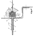
- Figure 1 is an elevational view, partially broken, of a device according to a first embodiment of the invention.
- Figure 2 is, on a larger scale, a section along line II-II of Figure 1.
- Figure 3 is a schematic representation of a horizontal section of this same embodiment, showing the position of the device under the action of a horizontal force applied to the curtain.
- Figure 4 is a cross section, similar to that of Figure 2, of a second embodiment of the device according to the invention.
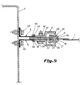
- Figure 5 is also a cross section similar to that of Figure 2 of a third embodiment of the device according to the invention.
- the embodiment of the closure device according to the invention comprises a curtain 1 which can be wound around a winding axis (not shown) and is intended for the closure of a bay, such as a garage entrance, workshop, shed, and also as a partition wall of a room, or to cover a swimming pool, a silo, etc.
- a bay such as a garage entrance, workshop, shed, and also as a partition wall of a room, or to cover a swimming pool, a silo, etc.
- This curtain 1 has flexible lateral edges 2, which project from the plane of the curtain and which are kept sliding in guide tracks 3, provided laterally on either side of the opening to be closed eg
- This device is essentially characterized in that the guide tracks 3 are mounted on a support 4, laterally delimiting the bay, in an elastic manner and / or pivoting around an axis substantially parallel to the longitudinal axis of these guideways, and this in such a way that the lateral edges 2 of the curtain can continue to be maintained in these guideways when the latter move relative to the support 4.
- the set of parts of the guide path which hold the edge of the curtain which is mounted resiliently and / or pivotally on the support 4. Means could however be provided to allow the release of these lateral edges 2 from their guide paths when the traction force exerted by the curtain on them exceeds a certain value.
- the guide tracks 3 are mounted by means of elastic means, forms of helical springs 5, on the support 4, so as to be able to thus undergo displacement in the direction of the curtain 1 when a force, illustrated by the arrow 6 in FIG. 3, is applied thereto.
- the guide tracks 3 are arranged on rods 7 extending vertically relative to the longitudinal axis of the latter and mounted with a certain clearance in holes 8 formed in the wall of the support 4, the latter being, in this form of construction, consisting of a metal box.
- the helical springs 5 are threaded on the rods 7 inside the box, pressing on the inside wall of the latter, on the opposite side of its wall on which the guide path 3 is mounted.
- the aforementioned rods 7 have a threaded free end 9 and are each mounted coaxially in a sleeve 10 passing with a certain clearance through the holes 8 formed in the support box 4, this sleeve being immobilized relative to the guide path 3 by a nut 11 screwed onto the threaded free end 9 of the rods 7.
- the springs 5, which are threaded on the sleeve 10 are held with a certain compression between the nut 11 and the inner face of the wall of the support box on which the guide path 3 is mounted. In this way, the springs exert a certain traction on the guide path 3 in a direction perpendicular to the longitudinal axis of the latter.
- a flexible sealing strip 12 for example made of rubber or plastic, is provided between the guide path 3 and the support box 4.
- One of the lateral longitudinal edges 13 of the sealing strip 12 has orifices which are crossed by the rods 7.
- the latter are fixed at regular distances from one another on the back 14 of the guide tracks 3, as shown clearly in FIG. 1.
- This edge 13 is held against the back 14 of the guide path 3 via the free end of the sleeves 10 directed towards this back, which is applied around the abovementioned orifices against this edge 13.
- the sealing strip 12 forms a loop 15 between the guide path 3 and the support box 4.
- the rods 7 freely cross the branch 16 of the loop 15 located on the side of the support box 4, so that it can move freely on the sleeve 10 threaded on the rod 7.
- the other branch 17 has the free edge 13 and is fixed against the back 14 of the guide path by the free end of the sleeve 10, as already described above.
- the projecting lateral edges 2 of the curtain 1 are formed by a succession of small juxtaposed identical blocks 2 ′, preferably made of a material hard plastic, located in the extension of each other and close to each other, being connected in a flexible way between them, for example like the blocks of a zipper known per se.
- these blocks can be as close as possible to each other as long as the lateral edges 2 remain flexible enough to allow the curtain to be wound around an axis.
- the guide tracks 3 each have two longitudinal edges 18 and 19 located on either side of the curtain 1 and directed towards each other in a direction substantially perpendicular to the curtain.
- these guide paths 3 surround the projecting edge 2 of the curtain 1.
- These two longitudinal edges 18 and 19, which therefore retain the protruding edge 2 of the curtain 1 in the guide tracks, are part of two separate sections of somewhat elastic material 20 and 21, which each have a cross section having a shape substantially Z-shaped.
- One of the two wings of these profiles 20 and 21 forms the abovementioned longitudinal edge, respectively 18 and 19, the other wing 22, respectively 23, forming the base of these profiles, which is held in a rigid metal profile.
- the two Z-shaped profiles 20 and 21 are held in the U-shaped profile 24 by an intermediate rod 27 clamped in the latter between the bases of these two profiles 20 and 21 and an intermediate rod 31 on either side of these profiles and the adjacent wing of the U-shaped profile.
- a support profile 28 also in U-shaped, the wings of which have flanges facing one towards the other.
- Contacts 32 can for example be arranged between the guide path 3 and the support 4 in order to detect the moment when the protruding edge 2 of the curtain 1 is released from the guide path and / or when the force 6 exerted on the curtain 1 exceeds a specified limit. These contacts 32 are then preferably connected to an alarm circuit for, for example, putting out of service and blocking the curtain in its winding or unwinding movement, or simply to activate a warning device. These contacts could also be provided inside the box and cooperate with the rods 7.
- means can advantageously be provided for intercepting the force 6 acting on the curtain when it reaches a certain limit, without the projecting edge 2 being released from its guide paths 3.
- the projecting edge 2 could for example be fixed to the curtain by means of low resistance extending between the curtain and its projecting edges 2.
- These means could for example be formed by a flange and pins having a resistance calculated so that these pins can break as soon as the force 6 reaches a predetermined limit. It would also be possible to provide, between the projecting edge 2 and the plane of the curtain, a zone of low resistance which can yield when the aforementioned force acting on the plane of the curtain reaches a certain level which is less than the force necessary to release the edge protruding 2 of its guide path.
- the embodiment of the device according to the invention shown in Figure 4 differs essentially from that of Figure 2 in that the elastic means are constituted by elements of substantially elastic foam 5, such as polyurethane foam or latex. These elements 5 extend over the entire length of the guide path 3 and thus make it possible to seal between the latter and the support 4 on which it is mounted, without the need for an additional strip. sealing, as in the previous embodiment.
- These foam elements 5 consist of bars of rectangular section and are arranged in a U-shaped profile 34 fixed by welding against the outer face of the support box 4. The lateral wings of this profile 34 have flanges 35 directed one towards the other against which one of the faces 38 of the foam elements 5 is applied.
- the Z profiles 20 and 21 are fixed over their entire length in a removable manner between two identical plates 37, one of the longitudinal edges of which has the appearance of a hook (25) and holds the profiles 20 and 21 in place, the opposite longitudinal edge being provided with support legs 36 applying against the face 39 of the foam elements 5 opposite to that resting against the flanges 35 of the profile 34.
- An intermediate plate 27 extends between the two plates 35 and the bases of the sections 20 and 21 and determines the distance separating the latter from each other.
- the hook-shaped edges 25 are applied in an elastically adjustable manner against the profiles 20 and 21 so as to be able to thus control the force acting by the latter on the edges 2 of the curtain 1, particularly the force which is necessary for clear the edges 2 of the guide path 3.
- the free edges 40 of the hooks 25 are slightly inclined by applying elastically against the profiles 20 and 21 and a bolt passing through the plates 37 and the intermediate plate 31 allows, by means of a nut 42 screwed on this bolt 41, to adjust the pressure exerted by these free edges 40 on the sections 20 and 21.
- the embodiment of the device according to the invention as shown in FIG. 5 differs essentially from that of FIG. 4 by the fact that the elastic means consist of two bands of elastic material 5, such as rubber or a plastic elastomer, which are subjected to a tensile force, while, in the embodiment according to FIG. 4, the foam strips 5 are subjected to a compressive force.
- One of the lateral edges of these strips 5 has a bead 43 held in a gutter 44 of the plates 37 applied against the intermediate plate 31.
- the other lateral edge of these strips is folded against the outside face of the support box 4 and is held against the latter by regularly spaced 45 bolts.
- stop means making it possible to limit the displacement of the guide tracks 3 in the direction of the curtain 1 when a force 6 is exerted on the latter.
- the stop is automatically obtained when all the turns of the spring are applied against each other. If the elastic means are formed of foam elements, the stop is obtained when these elements are fully compressed. If elastic bands are used, which are therefore subjected to traction, it could be important to incorporate therein an armature making it possible to limit the elongation of the band in the direction of traction.
- the curtain is constantly under a controlled horizontal tension and expansions or shrinkages of the curtain which could occur following temperature fluctuations will be automatically compensated by the elastic means. This will also be the case for variations of distance between the guide paths on either side of the curtain, eg if the latter are not perfectly parallel.
- the guide tracks can pivot around an axis parallel to their longitudinal axis, the traction exerted by the curtain 1, via the edges 2, will always be distributed symmetrically on the two sections 20 and 21, in particular on the two flanges 18 and 19 respectively of the latter, and this always in a direction substantially parallel to the core 34 of these two sections 20 and 21.
- the guide path 3 could be mounted on the support 4 by means of a hinge or a series of successive hinges, the axis of rotation of which is parallel to the axis of this guide path.
- these paths guide could be mounted on their supports so as to be able to undergo only a translation along the plane of the curtain in the closed position, the elastic means would then not allow the pivoting of the guide path.
- the edge 2 of the curtain 1 could be provided with spaced guide means, such as rollers or pads extending at a certain distance from each other on the edge of the curtain. It would therefore not be a substantially continuous projecting edge.
- the curtain 1 consists of a tarpaulin and has at least one substantially elastic zone 50, formed for example by a strip of elastic material shown diagrammatically in FIG. 1, s' extending over the entire length of the curtain 1, in the direction of its lateral edges.
- This area 50 can in principle be located anywhere on the curtain, but for reasons of symmetry, eg it will preferably be near each of its lateral edges 2 or possibly in the middle. However, a single elastic zone could also be provided near one of the two lateral edges 2. In a variant, the entire curtain could be made of a substantially elastic material.
- the guide tracks 3 could be pivotally mounted or be fixed on the support 4. We could even combine these latter embodiments with those where the guide tracks 3 are resiliently mounted on the support 4.
- the curtain preferably consists of a fully flexible continuous sheet, in contrast to the curtains which comprise at regular distances horizontal bars which are slightly flexible or not, which provide lateral guidance of the curtain.
Landscapes
- Engineering & Computer Science (AREA)
- Structural Engineering (AREA)
- Architecture (AREA)
- Civil Engineering (AREA)
- Curtains And Furnishings For Windows Or Doors (AREA)
- Control And Other Processes For Unpacking Of Materials (AREA)
- Removal Of Insulation Or Armoring From Wires Or Cables (AREA)
- Operating, Guiding And Securing Of Roll- Type Closing Members (AREA)
- Sink And Installation For Waste Water (AREA)
- Centrifugal Separators (AREA)
- Scissors And Nippers (AREA)
- Blinds (AREA)
- Storing, Repeated Paying-Out, And Re-Storing Of Elongated Articles (AREA)
- Tents Or Canopies (AREA)
Claims (27)
- Vorrichtung zum Verschließen, Trennen oder Abdecken umfassend einen Rolladen mit flexiblen Seitenkanten, welche in Führungen gehalten sind, dadurch gekennzeichnet, daß die Führungen (3) federnd und/oder um eine in etwa parallel zu ihren Längsachsen verlaufende Achse verschwenkbar auf einem Gestell (4) festgelegt sind, wobei die Seitenkanten (2) bei einer Rotation und/oder Verschiebung der Führungen (3) gegenüber dem Gestell (4) weiterhin innerhalb der Führungen (3) gehalten werden.
- Vorrichtung nach Anspruch 1, dadurch gekennzeichnet, daß die Führungen (3) mittels elastischer Mittel (5) in der Weise am Gestell (4) festgelegt sind, daß sie eine Verschiebung in Richtung des Rolladens (1) erfahren können, wenn eine Kraft (6) auf letzteren ausgeübt wird.
- Vorrichtung nach Anspruch 2, dadurch gekennzeichnet, daß die elastischen Mittel (5) so angeordnet sind, daß sie dauernd einen Zug auf die Seitenkanten (2) des Rolladens (1) ausüben.
- Vorrichtung nach einem der Ansprüche 2 oder 3, dadurch gekennzeichnet, daß die Führungen (3) auf Bolzen (7) angeordnet sind, welche sich in etwa vertikal in Bezug auf die Längsachse der Führungen (3) erstrecken und mit einem gewissen Spiel in in einer Wandung des Gestells (4) vorgesehenen Durchbrüchen (8) gehalten sind, wobei die elastischen Mittel eine Schraubenfeder (5) umfassen, die auf der der Führung (3) gegenüberliegenden Seite der Wandung (4) auf den Bolzen (7) aufgefädelt ist und sich auf dieser Wandung (4) abstützt.
- Vorrichtung nach Anspruch 4, dadurch gekennzeichnet, daß der Bolzen (7) ein mit einem Gewinde versehenes freies Ende aufweist und koaxial innerhalb einer Hülse (10) angebracht ist, welche Hülse (10) sich mit einem gewissen Spiel durch den in der Wandung des Gestells (4) ausgesparten Durchbruch (8) hindurch erstreckt und um unbeweglich gegenüber der Führung (3) zu sein mit einer auf das gewindete freie Ende des Bolzens (7) aufgeschraubten Mutter (11) gesichert ist, wobei die Feder (5) zwischen der Mutter (11) und der dieser zugewandten Oberfläche der Wandung des Gestells (4) gehalten ist.
- Vorrichtung nach einem der Ansprüche 2 bis 5, dadurch gekennzeichnet, daß ein biegsames Band (12), beispielsweise eine Windabdichtung, zwischen der Führung (3) und dem Gestell (4), auf welchem die Führung (3) festgelegt ist, vorgesehen ist.
- Vorrichtung nach Anspruch 6, dadurch gekennzeichnet, daß eine der Seitenkanten (13) des Dichtungsbandes (12) von den Bolzen (7) durchsetzte Öffnungen aufweist, welche Bolzen (7) in bestimmten Abständen zueinander am Rücken (14) der Führungen (3) festgelegt sind, wobei die Seitenkanten (13) mittels der freien, dem Rücken (14) zugewandten Enden der Hülsen (10), die sich rings um die Öffnungen an der Seitenkante (13) des Dichtungsbandes (12) anlegen, nahe bei diesem Rücken (14) gehalten ist.
- Vorrichtung nach Anspruch 6 oder 7, dadurch gekennzeichnet, daß das Dichungsband (12) zwischen der Führung (3) und dem Gestell (4), auf welchem die Führung (3) festgelegt ist, zu einer Schlaufe (15) gebogen ist, wobei die die Führung (3) tragenden Bolzen (7) den beim Gestell (4) befindlichen Schenkel (16) der Schlaufe (15) durchsetzen und die Seitenkante (13) des anderen Schenkels (17) am Rücken der Führung festgelegt ist.
- Vorrichtung nach Anspruch 2 oder 3, dadurch gekennzeichnet, daß die elastischen Mittel (5) Elemente aus im wesentlichen elastischen Schaumstoff umfassen.
- Vorrichtung nach Anspruch 2 oder 3, dadurch gekennzeichnet, daß die elastischen Mittel (5) aus einem im wesentlichen elastischen Material gefertigte Bänder umfassen.
- Vorrichtung nach einem der Ansprüche 1 bis 10, dadurch gekennzeichnet, daß die Seitenkanten (2) des Rolladens (1) aus dessen Ebene vorkragen und vorzugsweise durch eine Aufeinanderfolge von nebeneinander angeordneten kleinen, gleichen, im wesentlichen starren Blöcken (2'), die untereinander biegsam verbunden sind, gebildet sind.
- Vorrichtung nach einem der Ansprüche 1 bis 11, dadurch gekennzeichnet, daß die Führungen (3) je zwei Längsrandleisten (18,19) aufweisen, die sich beiderseits des Rolladens (1) erstrecken und einander zugewandt sind, sodaß sie die Seitenkante (2) des innerhalb der Führung (3) gehalten Rolladens (1) zumindest teilweise umschließen.
- Vorrichtung nach Anspruch 12, dadurch gekennzeichnet, daß die Führungen (3) zumindest ein, die Längsseitenkanten (18,19) aufweisendes Profilblech (20,21) umfassen, welches die Seitenkante (2) des Rolladens (1) zumindest teilweise umschließt, wobei das Profilblech (20, 21) aus einem geringfügig elastischen Material gefertigt ist, damit die Seitenkante (2) sich bei Aufbringen einer gewissen Kraft (6) auf den Rolladen (1) aus der Führung (3) lösen kann.
- Vorrichtung nach Anspruch 13, dadurch gekennzeichnet, daß jede Führung (3) zwei separate, aus einem geringfügig elastischen Material gefertigte, sich im Abstand voneinander erstreckende Profilbleche (20, 21) aufweist, deren Basen (22, 23) in einem U-förmigen, im wesentlichen starren Profilblech (24) gehalten sind, dessen Schenkel auch die einander zugewandten Randleisten (25, 26) aufweist.
- Vorrichtung nach Anspruch 14, dadurch gekennzeichnet, daß die beiden Profilbleche (20, 21) einen im wesentlichen Z-förmigen Querschnitt aufweisen, dessen erster Schenkel die Längsrandleiste (18, 19) und dessen anderer Schenkel (22, 23) die Basis bilden, wobei diese beiden Z-förmigen Profilbleche im U-förmigen Profilblech mittels eines zwischen den beiden Z-förmigen Profilblechen (20, 21) eingeklemmten Zwischenstückes (27) und jeweils eines zwischen Z-förmigen Profilblech und dem diesem benachbarten Schenkel des U-förmigen Profilbleches angeordneten Zwischenstückes (31) gehalten sind.
- Vorrichtung nach einem der Ansprüche 13 bis 15, dadurch gekennzeichnet, daß die Profilbleche (20, 21) zwischen zwei lösbar aneinander festgelegten, sich entlang der Führungen (3) erstreckenden Platten (37) gehalten sind, wobei die einen Längsseitenkanten dieser Platten (37) die Form eines Hakens (25) aufweisen und mit den Profilblechen (20, 21) zusammenwirken, und die anderen Seitenkanten mit den elastischen Mitteln (5) zusammenwirken.
- Vorrichtung nach Anspruch 16, dadurch gekennzeichnet, daß sich eine Zwischenplatte (27) zwischen den zwei Platten (37) und den Profilblechen (20, 21) erstreckt.
- Vorrichtung nach einem der Ansprüche 9 oder 11 bis 17, dadurch gekennzeichnet, daß die Schaumstoff-Elemente (5) in einem auf dem Gestell (4) festgelegten U-förmigen Profilblech (34) angeordnet sind, wobei die Seitenschenkel dieses Profilbleches (34) einander zugewandte Randleisten (35) aufweisen, an denen die erste Oberfläche (38) der Schaumstoff-Elemente (5) anliegt und daß die Führungen (3) mit einer Abstützvorrichtung (36) ausgestattet sind, die mit der, der an den Randleisten anliegenden Oberfläche gegenüberliegenden Oberfläche (39) der Schaumstoff-Elemente (5) zusammenwirkt.
- Vorrichtung nach Anspruch 18, dadurch gekennzeichnet, daß die andere Längsseitenkante der Platte (37) mit einem Schenkel (36) versehen ist, welcher sich entlang der Oberfläche (38) der Schaumstoffblöcke (5) erstreckt und damit die Abstützvorrichtung bildet.
- Vorrichtung nach Anspruch 16, dadurch gekennzeichnet, daß, wenn die elastischen Mittel durch Bänder (5) aus elastischem Material gebildet sind, eine deren Seitenkanten (39) von der Längsseitenkante der Platte (37) gehalten ist und die andere Längsseitenkante (40) des elastischen Bandes (5) am Gestell (4) festgelegt ist.
- Vorrichtung nach einem der Ansprüche 16 bis 20, dadurch gekennzeichnet, daß die die Form eines Hakens (25) aufweisenden Seitenkante der Platten (37) in einstellbarer Weise federnd an den Profilblechen (20, 21) angebracht sind, um so die von ihnen auf die Seitenkanten (2) des Rolladens (1) aufgebrachte Kraft steuern zu können.
- Vorrichtung nach einem der Ansprüche 2 bis 21, dadurch gekennzeichnet, daß Anschlagmittel vorgesehen sind, die eine Begrenzung der Verschiebung der Führungen (3) in Richtung Rolladen (1) beim Ausüben einer Kraft auf den Rolladen (1) erlauben.
- Vorrichtung nach einem der Ansprüche 1 bis 22, dadurch gekennzeichnet, daß zumindest ein Kontakt (32) vorgesehen ist, der das Erkennen des Momentes des Lösens der Seitenkante (2) des Rolladens (1) aus der Führung (3) und/oder des Momentes, in dem die auf den Rolladen (1) wirkende Kraft einen vorgegebenen Grenzwert übersteigt, erlaubt, wobei der Kontakt (32) in einen Alarmschaltkreis geschaltet ist.
- Vorrichtung zum Verschließen, Trennen oder Abdecken umfassend einen Rolladen (1) mit flexiblen Seitenkanten (2), welche in Führungen (3) gehalten sind, dadurch gekennzeichnet, daß der Rolladen (1) zwischen seiner vorkragenden Seitenkante (2) und der eigentlichen Rolladenebene eine enge, sich über die gesamte Länge der Seitenkante (2) erstreckende, vorzugsweise benachbart zu letzterer angeordnete, geringe Festigkeit aufweisende Zone (33) aufweist, welche nachgibt, sobald die auf den Rolladen (1) einwirkende Kraft einen vorgegebenen Grenzwert erreicht, welcher Grenzwert niedriger als die für die Lösung der Seitenkante (2) aus den Führungen (3) notwendige Kraft ist.
- Vorrichtung zum Verschließen, Trennen oder Abdecken umfassend einen Rolladen (1) mit flexiblen Seitenkanten (2), welche in Führungen (3) gehalten sind, dadurch gekennzeichnet, daß der Rolladen (1) zumindest ein aus elastischem Material gebildetes Band (50) aufweist, das sich durchgehend über die gesamte Länge des Rolladens (1) in Richtung der Längsseitenkanten (2) erstreckt.
- Vorrichtung nach Anspruch 25, dadurch gekennzeichnet, daß der Rolladen durch eine durchgehende Plane gebildet ist, die eine im wesentlichen elasische, ununterbrochene Zone (50) aufweist, welche sich in der Nähe jeder der Längsseitenkanten des Rolladens (1) erstreckt.
- Vorrichtung nach Anspruch 25, dadurch gekennzeichnet, daß der Rolladen (1) aus einem im wesentlichen elastischen Material gefertigt ist.
Applications Claiming Priority (3)
| Application Number | Priority Date | Filing Date | Title |
|---|---|---|---|
| BE9100499A BE1004897A3 (fr) | 1991-05-24 | 1991-05-24 | Dispositif de fermeture, de separation ou de couverture. |
| BE9100499 | 1991-05-24 | ||
| PCT/BE1992/000017 WO1992020895A1 (fr) | 1991-05-24 | 1992-05-15 | Dispositif de fermeture, de separation ou de couverture |
Publications (2)
| Publication Number | Publication Date |
|---|---|
| EP0587586A1 EP0587586A1 (de) | 1994-03-23 |
| EP0587586B1 true EP0587586B1 (de) | 1997-03-19 |
Family
ID=3885521
Family Applications (1)
| Application Number | Title | Priority Date | Filing Date |
|---|---|---|---|
| EP92909384A Expired - Lifetime EP0587586B1 (de) | 1991-05-24 | 1992-05-15 | Verschluss-, trenn- und abdeckungsvorrichtung |
Country Status (11)
| Country | Link |
|---|---|
| US (1) | US5526865A (de) |
| EP (1) | EP0587586B1 (de) |
| AT (1) | ATE150520T1 (de) |
| AU (1) | AU1676292A (de) |
| BE (1) | BE1004897A3 (de) |
| CA (1) | CA2109823C (de) |
| DE (1) | DE69218429T2 (de) |
| DK (1) | DK0587586T3 (de) |
| ES (1) | ES2101844T3 (de) |
| GR (1) | GR3023787T3 (de) |
| WO (1) | WO1992020895A1 (de) |
Families Citing this family (68)
| Publication number | Priority date | Publication date | Assignee | Title |
|---|---|---|---|---|
| US5579820A (en) | 1994-11-10 | 1996-12-03 | Lepage; Robert | Roll-up door for vehicle shelters |
| US5944086A (en) * | 1995-02-10 | 1999-08-31 | Rite-Hite Holding Corporation | Curtain bottom tensioning assembly |
| US5638883A (en) * | 1995-02-10 | 1997-06-17 | Rite-Hite Corporation | Breakaway guide assembly for a roller door |
| BR9607591A (pt) * | 1995-02-10 | 1998-07-07 | Rite Hite Corp | Conjunto de tensionamento de parte inferior de cortina |
| US6089305A (en) * | 1995-02-10 | 2000-07-18 | Rite-Hite Holding Corporation | Curtain guiding assembly for a soft edge door with a selectively tensioned leading edge |
| US6698490B2 (en) | 1996-05-28 | 2004-03-02 | Rite-Hite Holding Corporation | Release mechanism for industrial doors |
| US5887385A (en) * | 1996-05-28 | 1999-03-30 | Rite-Hite Holding Corporation | Release mechanism for industrial doors |
| FR2756866B1 (fr) * | 1996-12-10 | 1999-01-22 | Kodak Pathe | Dispositif de fermeture a rideau souple pour local a l'abri de la lumiere |
| FR2762642B1 (fr) | 1997-04-23 | 1999-07-30 | Bernard Simon | Dispositif de guidage d'une porte a rideau souple |
| DE29906582U1 (de) * | 1999-04-14 | 2000-09-21 | Langenbach, Guido, 37191 Katlenburg-Lindau | Crashschutzvorrichtung |
| FR2804159B1 (fr) * | 2000-01-20 | 2002-09-06 | Bernard Simon | Lames semi-rigides pour porte de manutention a rideau souple |
| EP1191184A1 (de) | 2000-09-25 | 2002-03-27 | Dynaco International | Verschlusseinrichtung für das Schliessen einer Öffnung |
| EP1233138A1 (de) * | 2001-02-16 | 2002-08-21 | Dynaco International | Vorrichtung mit einem flexiblen Verschluss |
| BE1014544A3 (fr) * | 2001-12-14 | 2003-12-02 | Dynaco Internat | Dispositif a volet avec chemins de guidage. |
| DE20200310U1 (de) * | 2002-01-10 | 2003-05-22 | Detenhoff, Oliver, 82284 Grafrath | Haussicherheitsanlage für einen Rollladen |
| BE1014712A3 (fr) * | 2002-03-20 | 2004-03-02 | Dynaco Internat | Dispositif a volet presentant des bords lateraux flexibles |
| US6722416B2 (en) * | 2002-04-03 | 2004-04-20 | Overhead Door Corporation | Flexible curtain rollup door with combination stiffening struts and windlocks |
| US6942003B2 (en) * | 2003-07-25 | 2005-09-13 | Service Door Industries Limited | Roll-up door curtain and guides and bottom bar therefor |
| CN1580479B (zh) * | 2003-08-12 | 2010-06-23 | 三和控股株式会社 | 薄板卷帘门装置 |
| FR2863646B1 (fr) * | 2003-12-11 | 2006-02-24 | Nergeco Sa | Porte a rideau relevable par enroulement a etancheite laterale amelioree |
| DE102004033982A1 (de) * | 2004-07-14 | 2006-02-02 | Arvinmeritor Gmbh | Führungsschiene für einen Rollo eines Schiebedachsystems |
| US20080093037A1 (en) * | 2004-12-10 | 2008-04-24 | Bernard Kraeutler | Door Provided With a Curtain Which is Raisable by Winding and Has an Improved Lateral Tightness |
| EP1840321A1 (de) * | 2006-03-29 | 2007-10-03 | Dynaco International S.A. | Vorrichtung zum Führen eines Rollvorhangs |
| DE102006017538B4 (de) * | 2006-04-13 | 2010-08-12 | Webasto Ag | Rolloanordnung für ein Fahrzeug |
| US8037921B2 (en) * | 2006-06-05 | 2011-10-18 | Rite-Hite Holding Corporation | Track and guide system for a door |
| US20070277943A1 (en) * | 2006-06-05 | 2007-12-06 | Rite-Hite Holding Corporation | Track and guide system for a door |
| US7748431B2 (en) * | 2006-06-05 | 2010-07-06 | Rite-Hite Holding Corporation | Track and guide system for a door |
| EP1953018B1 (de) * | 2007-01-31 | 2010-03-17 | ArvinMeritor GmbH | Führungssystem für ein Rollo eines Schiebedachsystems |
| US8113265B2 (en) * | 2009-03-02 | 2012-02-14 | Rite-Hite Holding Corporation | Washdown door |
| US8408274B2 (en) | 2009-10-26 | 2013-04-02 | Rajiva Dwarka | Architectural apparatus and method |
| TWI499713B (zh) * | 2009-11-06 | 2015-09-11 | Komatsu Denki Sangyo Kabushiki Kaisha | 薄片活動遮門的薄片導引 |
| US20120012260A1 (en) * | 2010-07-16 | 2012-01-19 | Leonard Elinson | Retractable shade assembly with adjustable side guides |
| TW201241297A (en) * | 2011-04-06 | 2012-10-16 | Komatsu Denki Sangyo Kabushiki Kaisha | Sheet shutter |
| US20160319593A1 (en) * | 2011-05-11 | 2016-11-03 | Rajiva A. Dwarka | Retractable curtain panel with track guide |
| US9347258B2 (en) * | 2011-05-11 | 2016-05-24 | Rajiva A. Dwarka | Retractable curtain panel with track guide |
| US20130068400A1 (en) * | 2011-05-11 | 2013-03-21 | Rajiva A. Dwarka | Retractable curtain panel with track guide |
| US20170009524A1 (en) * | 2011-05-11 | 2017-01-12 | Rajiva A. Dwarka | Retractable curtain panel and enhanced stiffeners |
| EP2757224B1 (de) * | 2011-06-24 | 2017-02-15 | Hayashiguchi Mfg Co., Ltd. | Rollleinwandvorrichtung |
| US9057219B1 (en) | 2011-08-30 | 2015-06-16 | Newell Window Furnishings, Inc. | Window covering with integrated side track |
| US9127501B1 (en) * | 2012-01-10 | 2015-09-08 | Stoebich Brandschutz Gmbh | Lead system for a fire and smoke protection device |
| US9249621B2 (en) | 2012-01-18 | 2016-02-02 | Rajiva A. Dwarka | Coil brush curtain assembly |
| DE102013204032A1 (de) * | 2013-03-08 | 2014-09-11 | HELLA Sonnen- und Wetterschutztechnik GmbH | Schalltechnisches Trennelement mit Dichtfunktion |
| US9222304B2 (en) * | 2013-04-12 | 2015-12-29 | Rite-Hite Holding Corporation | Systems and methods to retain and refeed door curtains |
| US9493984B2 (en) | 2013-04-12 | 2016-11-15 | Rite-Hite Holding Corporation | Systems and methods to retain and refeed door curtains |
| KR20150069262A (ko) * | 2013-12-13 | 2015-06-23 | 현대자동차주식회사 | 파노라마 선루프용 블라인드의 처짐방지장치 |
| JP6228504B2 (ja) * | 2014-04-11 | 2017-11-08 | フクビ化学工業株式会社 | スクリーン装置およびその製造方法 |
| JP6309832B2 (ja) * | 2014-06-17 | 2018-04-11 | セイキ住工株式会社 | 巻取式スクリーン装置 |
| EP2987667B1 (de) | 2014-08-18 | 2019-10-09 | Inalfa Roof Systems Group B.V. | Führung und damit ausgerüstete Sonnenschutzanordnung |
| EP2987668B1 (de) | 2014-08-18 | 2019-04-24 | Inalfa Roof Systems Group B.V. | Sonnenschutzanordnung |
| JP6453624B2 (ja) * | 2014-11-25 | 2019-01-16 | 文化シヤッター株式会社 | シャッター用ガイドレールの構造 |
| CN104527382B (zh) * | 2014-12-30 | 2017-03-08 | 上海万超汽车天窗有限公司 | 全景天窗车顶总成 |
| US10428570B2 (en) | 2015-01-21 | 2019-10-01 | Entrematic Belgium Nv | Wind safe door |
| EP3098376A1 (de) * | 2015-05-29 | 2016-11-30 | Plastex SA | Pfosten für ein beschattungssystem, entfernbarer flansch des pfostens und entsprechendes kopplungsteil |
| ES2580553B1 (es) * | 2016-02-09 | 2017-02-13 | Iaso, S.A. | Cuerpo de guía para elementos deslizantes laminares |
| NL2016892B1 (nl) | 2016-06-03 | 2018-01-12 | Metaal En Kunststoffen Ind Snelder B V | Scherminrichting voor een warenhuis |
| WO2018001915A1 (en) | 2016-06-29 | 2018-01-04 | Assa Abloy Entrance Systems Ab | Safety door with ultrasonic detectors |
| US9719292B1 (en) * | 2016-08-03 | 2017-08-01 | Defender Screens International LLC | Self-tensioning magnetic tracks and track assemblies |
| US11421474B2 (en) * | 2016-08-03 | 2022-08-23 | Defender Screens International, Llc | Self-tensioning magnetic tracks and track assemblies |
| US20190048658A1 (en) * | 2017-08-09 | 2019-02-14 | Professional Blinds System Inc. | Construction assembly for installing a roller blind or the like |
| EP4582664A3 (de) | 2018-11-30 | 2025-12-17 | Rytec Corporation | Türanordnung mit türplatte mit weichem boden |
| US11326395B2 (en) | 2019-04-03 | 2022-05-10 | Michael Heissenberg | Retractable screen with horizontal tensioning track and vertical biasing member |
| CN112440697B (zh) | 2019-08-27 | 2023-11-24 | 英纳法天窗系统集团有限公司 | 遮阳系统及其部件的制造方法 |
| ES1239394Y (es) * | 2019-10-10 | 2020-06-22 | Producciones Mitjavila Sau | Estructura de guiado de lona enrollable |
| US12180786B2 (en) | 2020-02-24 | 2024-12-31 | Defender Screens International LLC | Retractable screen systems |
| GB2599962B (en) * | 2020-10-19 | 2023-09-13 | Amsafe Bridport Ltd | An aircraft compartmental barrier |
| IT202100029276A1 (it) * | 2021-11-19 | 2023-05-19 | Sgheiz Solutions | Guida per porta ad avvolgimento rapido |
| US12435565B2 (en) * | 2022-02-10 | 2025-10-07 | Kolar L. Seshasai | High wind tolerant track assembly for a motorized retractable screen |
| NL2037011B1 (en) * | 2024-02-12 | 2025-08-20 | Kertus Beheer B V | Screen arrangement |
Family Cites Families (12)
| Publication number | Priority date | Publication date | Assignee | Title |
|---|---|---|---|---|
| US1632742A (en) * | 1925-05-13 | 1927-06-14 | Ernest E Minard | Shade guide |
| US1736432A (en) * | 1928-01-16 | 1929-11-19 | Rolscreen Co | Plaster-channel installation for screen guides |
| US1840454A (en) * | 1931-08-20 | 1932-01-12 | Francis M Kennedy | Roller screen |
| CH192088A (de) * | 1936-12-23 | 1937-07-31 | Jeker Werner | Führungseinrichtung für Storen, Rouleaux, Blachendächer an Autos oder Zelten, Autokühlerdecken usw. |
| DE8525625U1 (de) * | 1985-09-09 | 1985-10-24 | Schieffer GmbH & Co KG, 4780 Lippstadt | Rolltor |
| GB8624735D0 (en) * | 1986-10-15 | 1986-11-19 | Clark Door Ltd | Roller door assemblies |
| BE906022A (fr) * | 1986-12-23 | 1987-04-16 | Coenraets B J | Dispositif a volet. |
| FR2624190B1 (fr) * | 1987-12-02 | 1990-05-11 | Nergeco Sa | Barre d'armature et de guidage pour un rideau souple de porte a relevage vertical |
| FR2656648A2 (fr) * | 1989-05-19 | 1991-07-05 | Nergeco Sa | Porte a rideau relevable renforcee par des bares d'armature horizontales. |
| EP0405093A3 (en) * | 1989-06-27 | 1991-07-17 | Rytec Corporation | Apparatus configured for maintaining a barrier in a position against a trans-barrier force less than a predetermined magnitude |
| US5176194A (en) * | 1989-08-08 | 1993-01-05 | Metaco Co., Ltd. | Roller screen unit |
| US5131450A (en) * | 1990-06-08 | 1992-07-21 | Dale Lichy | Closure assembly for structural members |
-
1991
- 1991-05-24 BE BE9100499A patent/BE1004897A3/fr not_active IP Right Cessation
-
1992
- 1992-05-15 US US08/142,371 patent/US5526865A/en not_active Expired - Lifetime
- 1992-05-15 AT AT92909384T patent/ATE150520T1/de not_active IP Right Cessation
- 1992-05-15 CA CA002109823A patent/CA2109823C/fr not_active Expired - Lifetime
- 1992-05-15 AU AU16762/92A patent/AU1676292A/en not_active Abandoned
- 1992-05-15 ES ES92909384T patent/ES2101844T3/es not_active Expired - Lifetime
- 1992-05-15 WO PCT/BE1992/000017 patent/WO1992020895A1/fr not_active Ceased
- 1992-05-15 DK DK92909384.7T patent/DK0587586T3/da active
- 1992-05-15 EP EP92909384A patent/EP0587586B1/de not_active Expired - Lifetime
- 1992-05-15 DE DE69218429T patent/DE69218429T2/de not_active Expired - Lifetime
-
1997
- 1997-06-18 GR GR970401427T patent/GR3023787T3/el unknown
Also Published As
| Publication number | Publication date |
|---|---|
| DK0587586T3 (da) | 1997-09-15 |
| AU1676292A (en) | 1992-12-30 |
| WO1992020895A1 (fr) | 1992-11-26 |
| ES2101844T3 (es) | 1997-07-16 |
| GR3023787T3 (en) | 1997-09-30 |
| ATE150520T1 (de) | 1997-04-15 |
| CA2109823C (fr) | 2005-12-27 |
| US5526865A (en) | 1996-06-18 |
| CA2109823A1 (fr) | 1992-11-26 |
| BE1004897A3 (fr) | 1993-02-16 |
| DE69218429D1 (de) | 1997-04-24 |
| EP0587586A1 (de) | 1994-03-23 |
| DE69218429T2 (de) | 1997-08-28 |
Similar Documents
| Publication | Publication Date | Title |
|---|---|---|
| EP0587586B1 (de) | Verschluss-, trenn- und abdeckungsvorrichtung | |
| EP0272733B1 (de) | Rolltorvorrichtung | |
| EP1518036B1 (de) | Verschlusseinrichtung zum wickeln auf eine welle | |
| EP2007963B1 (de) | Verschlussvorrichtung mit einem flexible seitenränder aufweisenden vorhang | |
| EP2122102A1 (de) | Vorrichtung mit einem flexiblen vorhang | |
| EP0500499B1 (de) | Store | |
| WO2002066776A1 (fr) | Dispositif a volet flexible | |
| FR2921405A1 (fr) | Dispositif de store | |
| EP0426524B1 (de) | Befestigungselement für eine Vorhangsstange | |
| FR3056615A1 (fr) | Dispositif de recouvrement d'un bassin de piscine | |
| FR2765617A1 (fr) | Dispositif d'articulation notamment pour planches et rideau mouvant forme de planches assemblees au moyen de tels dispositifs | |
| CH670132A5 (de) | ||
| FR2753743A1 (fr) | Nouveau type de store ou article similaire | |
| EP1558825B1 (de) | Komposit-unterdecke mit aufgespannter leinwand | |
| EP0994219A1 (de) | Überströmtes Wehr mit kippbarer Wehrklappe | |
| EP4400688B1 (de) | Rollladenschloss und zugehörige anlage | |
| BE1009515A3 (fr) | Cale d'epaisseur pour la fixation d'elements d'huisserie. | |
| BE1005266A5 (fr) | Dispositif de fixation d'un vitrage sur un support. | |
| FR2844541A1 (fr) | Dispositif de fermeture etanche d'une porte coulissante | |
| FR2487422A1 (fr) | Perfectionnements aux dispositifs de verrouillage automatique de volets roulants | |
| FR2538026A1 (fr) | Portail perfectionne a ossature metallique et garnissage generalement en bois | |
| FR2582712A1 (fr) | Dispositif de verrouillage pour persienne metallique et la persienne obtenue | |
| FR2508092A1 (fr) | Dispositif formant baie comprenant un element de glace dit " basculant ", et vehicules, batiments equipes avec ce dispositif | |
| FR2514400A1 (fr) | Dispositif de survitrage pour vantail de fenetre ou porte | |
| FR2782116A1 (fr) | Fixation pour stores a enroulement |
Legal Events
| Date | Code | Title | Description |
|---|---|---|---|
| PUAI | Public reference made under article 153(3) epc to a published international application that has entered the european phase |
Free format text: ORIGINAL CODE: 0009012 |
|
| 17P | Request for examination filed |
Effective date: 19931118 |
|
| AK | Designated contracting states |
Kind code of ref document: A1 Designated state(s): AT BE CH DE DK ES FR GB GR IT LI LU NL SE |
|
| 17Q | First examination report despatched |
Effective date: 19950829 |
|
| GRAG | Despatch of communication of intention to grant |
Free format text: ORIGINAL CODE: EPIDOS AGRA |
|
| GRAH | Despatch of communication of intention to grant a patent |
Free format text: ORIGINAL CODE: EPIDOS IGRA |
|
| GRAH | Despatch of communication of intention to grant a patent |
Free format text: ORIGINAL CODE: EPIDOS IGRA |
|
| GRAA | (expected) grant |
Free format text: ORIGINAL CODE: 0009210 |
|
| AK | Designated contracting states |
Kind code of ref document: B1 Designated state(s): AT BE CH DE DK ES FR GB GR IT LI LU NL SE |
|
| REF | Corresponds to: |
Ref document number: 150520 Country of ref document: AT Date of ref document: 19970415 Kind code of ref document: T |
|
| REG | Reference to a national code |
Ref country code: CH Ref legal event code: EP |
|
| REF | Corresponds to: |
Ref document number: 69218429 Country of ref document: DE Date of ref document: 19970424 |
|
| ITF | It: translation for a ep patent filed | ||
| REG | Reference to a national code |
Ref country code: CH Ref legal event code: NV Representative=s name: ISLER & PEDRAZZINI AG |
|
| GBT | Gb: translation of ep patent filed (gb section 77(6)(a)/1977) |
Effective date: 19970512 |
|
| RAP2 | Party data changed (patent owner data changed or rights of a patent transferred) |
Owner name: DYNACO INTERNATIONAL |
|
| REG | Reference to a national code |
Ref country code: ES Ref legal event code: FG2A Ref document number: 2101844 Country of ref document: ES Kind code of ref document: T3 |
|
| REG | Reference to a national code |
Ref country code: GR Ref legal event code: FG4A Free format text: 3023787 |
|
| NLT2 | Nl: modifications (of names), taken from the european patent patent bulletin |
Owner name: DYNACO INTERNATIONAL |
|
| REG | Reference to a national code |
Ref country code: DK Ref legal event code: T3 |
|
| PLBE | No opposition filed within time limit |
Free format text: ORIGINAL CODE: 0009261 |
|
| 26N | No opposition filed | ||
| REG | Reference to a national code |
Ref country code: GB Ref legal event code: IF02 |
|
| REG | Reference to a national code |
Ref country code: CH Ref legal event code: PCAR Free format text: ISLER & PEDRAZZINI AG;POSTFACH 1772;8027 ZUERICH (CH) |
|
| PGFP | Annual fee paid to national office [announced via postgrant information from national office to epo] |
Ref country code: LU Payment date: 20080516 Year of fee payment: 17 Ref country code: CH Payment date: 20080530 Year of fee payment: 17 |
|
| PGFP | Annual fee paid to national office [announced via postgrant information from national office to epo] |
Ref country code: AT Payment date: 20080531 Year of fee payment: 17 |
|
| PGFP | Annual fee paid to national office [announced via postgrant information from national office to epo] |
Ref country code: SE Payment date: 20080509 Year of fee payment: 17 |
|
| PGFP | Annual fee paid to national office [announced via postgrant information from national office to epo] |
Ref country code: GR Payment date: 20080530 Year of fee payment: 17 |
|
| PGRI | Patent reinstated in contracting state [announced from national office to epo] |
Ref country code: IT Effective date: 20090801 |
|
| REG | Reference to a national code |
Ref country code: CH Ref legal event code: PL |
|
| PG25 | Lapsed in a contracting state [announced via postgrant information from national office to epo] |
Ref country code: LI Free format text: LAPSE BECAUSE OF NON-PAYMENT OF DUE FEES Effective date: 20090531 Ref country code: CH Free format text: LAPSE BECAUSE OF NON-PAYMENT OF DUE FEES Effective date: 20090531 Ref country code: AT Free format text: LAPSE BECAUSE OF NON-PAYMENT OF DUE FEES Effective date: 20090515 |
|
| PG25 | Lapsed in a contracting state [announced via postgrant information from national office to epo] |
Ref country code: GR Free format text: LAPSE BECAUSE OF NON-PAYMENT OF DUE FEES Effective date: 20091202 |
|
| PGRI | Patent reinstated in contracting state [announced from national office to epo] |
Ref country code: IT Effective date: 20090801 |
|
| PG25 | Lapsed in a contracting state [announced via postgrant information from national office to epo] |
Ref country code: LU Free format text: LAPSE BECAUSE OF NON-PAYMENT OF DUE FEES Effective date: 20090515 |
|
| PG25 | Lapsed in a contracting state [announced via postgrant information from national office to epo] |
Ref country code: SE Free format text: LAPSE BECAUSE OF NON-PAYMENT OF DUE FEES Effective date: 20090516 |
|
| PGFP | Annual fee paid to national office [announced via postgrant information from national office to epo] |
Ref country code: FR Payment date: 20110607 Year of fee payment: 20 Ref country code: ES Payment date: 20110628 Year of fee payment: 20 |
|
| PGRI | Patent reinstated in contracting state [announced from national office to epo] |
Ref country code: IT Effective date: 20110616 |
|
| PGFP | Annual fee paid to national office [announced via postgrant information from national office to epo] |
Ref country code: NL Payment date: 20110531 Year of fee payment: 20 Ref country code: GB Payment date: 20110525 Year of fee payment: 20 Ref country code: DK Payment date: 20110525 Year of fee payment: 20 |
|
| REG | Reference to a national code |
Ref country code: GB Ref legal event code: 732E Free format text: REGISTERED BETWEEN 20110804 AND 20110810 |
|
| PGFP | Annual fee paid to national office [announced via postgrant information from national office to epo] |
Ref country code: BE Payment date: 20110630 Year of fee payment: 20 Ref country code: IT Payment date: 20110527 Year of fee payment: 20 |
|
| PGFP | Annual fee paid to national office [announced via postgrant information from national office to epo] |
Ref country code: DE Payment date: 20110629 Year of fee payment: 20 |
|
| REG | Reference to a national code |
Ref country code: NL Ref legal event code: TD Effective date: 20111209 |
|
| REG | Reference to a national code |
Ref country code: FR Ref legal event code: TP Owner name: DYNACO EUROPE NV, BE Effective date: 20111212 |
|
| REG | Reference to a national code |
Ref country code: ES Ref legal event code: PC2A Owner name: DYNACO EUROPE N.V. Effective date: 20120126 |
|
| REG | Reference to a national code |
Ref country code: DE Ref legal event code: R082 Ref document number: 69218429 Country of ref document: DE Representative=s name: GRUENECKER, KINKELDEY, STOCKMAIR & SCHWANHAEUS, DE |
|
| REG | Reference to a national code |
Ref country code: DE Ref legal event code: R082 Ref document number: 69218429 Country of ref document: DE Representative=s name: GRUENECKER PATENT- UND RECHTSANWAELTE PARTG MB, DE Effective date: 20120312 Ref country code: DE Ref legal event code: R082 Ref document number: 69218429 Country of ref document: DE Representative=s name: GRUENECKER, KINKELDEY, STOCKMAIR & SCHWANHAEUS, DE Effective date: 20120312 Ref country code: DE Ref legal event code: R081 Ref document number: 69218429 Country of ref document: DE Owner name: DYNACO EUROPE NV, BE Free format text: FORMER OWNER: DYNACO INTERNATIONAL, BRUESSEL/BRUXELLES, BE Effective date: 20120312 |
|
| REG | Reference to a national code |
Ref country code: DE Ref legal event code: R071 Ref document number: 69218429 Country of ref document: DE |
|
| REG | Reference to a national code |
Ref country code: DE Ref legal event code: R071 Ref document number: 69218429 Country of ref document: DE |
|
| REG | Reference to a national code |
Ref country code: NL Ref legal event code: V4 Effective date: 20120515 |
|
| BE20 | Be: patent expired |
Owner name: DYNACO EUROPE N.V. Effective date: 20120515 |
|
| REG | Reference to a national code |
Ref country code: DK Ref legal event code: EUP |
|
| REG | Reference to a national code |
Ref country code: GB Ref legal event code: PE20 Expiry date: 20120514 |
|
| PG25 | Lapsed in a contracting state [announced via postgrant information from national office to epo] |
Ref country code: DE Free format text: LAPSE BECAUSE OF EXPIRATION OF PROTECTION Effective date: 20120516 |
|
| PG25 | Lapsed in a contracting state [announced via postgrant information from national office to epo] |
Ref country code: GB Free format text: LAPSE BECAUSE OF EXPIRATION OF PROTECTION Effective date: 20120514 |
|
| REG | Reference to a national code |
Ref country code: ES Ref legal event code: FD2A Effective date: 20130711 |
|
| PG25 | Lapsed in a contracting state [announced via postgrant information from national office to epo] |
Ref country code: ES Free format text: LAPSE BECAUSE OF EXPIRATION OF PROTECTION Effective date: 20120516 |