EP0587660B1 - Mehrschichtiges rohr und verfahren zu seiner herstellung - Google Patents
Mehrschichtiges rohr und verfahren zu seiner herstellung Download PDFInfo
- Publication number
- EP0587660B1 EP0587660B1 EP92911407A EP92911407A EP0587660B1 EP 0587660 B1 EP0587660 B1 EP 0587660B1 EP 92911407 A EP92911407 A EP 92911407A EP 92911407 A EP92911407 A EP 92911407A EP 0587660 B1 EP0587660 B1 EP 0587660B1
- Authority
- EP
- European Patent Office
- Prior art keywords
- fibres
- pipe
- thermoplastic
- laminated
- mat
- Prior art date
- Legal status (The legal status is an assumption and is not a legal conclusion. Google has not performed a legal analysis and makes no representation as to the accuracy of the status listed.)
- Expired - Lifetime
Links
Images


Classifications
-
- F—MECHANICAL ENGINEERING; LIGHTING; HEATING; WEAPONS; BLASTING
- F16—ENGINEERING ELEMENTS AND UNITS; GENERAL MEASURES FOR PRODUCING AND MAINTAINING EFFECTIVE FUNCTIONING OF MACHINES OR INSTALLATIONS; THERMAL INSULATION IN GENERAL
- F16L—PIPES; JOINTS OR FITTINGS FOR PIPES; SUPPORTS FOR PIPES, CABLES OR PROTECTIVE TUBING; MEANS FOR THERMAL INSULATION IN GENERAL
- F16L33/00—Arrangements for connecting hoses to rigid members; Rigid hose-connectors, i.e. single members engaging both hoses
- F16L33/22—Arrangements for connecting hoses to rigid members; Rigid hose-connectors, i.e. single members engaging both hoses with means not mentioned in the preceding groups for gripping the hose between inner and outer parts
-
- B—PERFORMING OPERATIONS; TRANSPORTING
- B29—WORKING OF PLASTICS; WORKING OF SUBSTANCES IN A PLASTIC STATE IN GENERAL
- B29C—SHAPING OR JOINING OF PLASTICS; SHAPING OF MATERIAL IN A PLASTIC STATE, NOT OTHERWISE PROVIDED FOR; AFTER-TREATMENT OF THE SHAPED PRODUCTS, e.g. REPAIRING
- B29C48/00—Extrusion moulding, i.e. expressing the moulding material through a die or nozzle which imparts the desired form; Apparatus therefor
- B29C48/03—Extrusion moulding, i.e. expressing the moulding material through a die or nozzle which imparts the desired form; Apparatus therefor characterised by the shape of the extruded material at extrusion
- B29C48/09—Articles with cross-sections having partially or fully enclosed cavities, e.g. pipes or channels
-
- B—PERFORMING OPERATIONS; TRANSPORTING
- B29—WORKING OF PLASTICS; WORKING OF SUBSTANCES IN A PLASTIC STATE IN GENERAL
- B29C—SHAPING OR JOINING OF PLASTICS; SHAPING OF MATERIAL IN A PLASTIC STATE, NOT OTHERWISE PROVIDED FOR; AFTER-TREATMENT OF THE SHAPED PRODUCTS, e.g. REPAIRING
- B29C48/00—Extrusion moulding, i.e. expressing the moulding material through a die or nozzle which imparts the desired form; Apparatus therefor
- B29C48/15—Extrusion moulding, i.e. expressing the moulding material through a die or nozzle which imparts the desired form; Apparatus therefor incorporating preformed parts or layers, e.g. extrusion moulding around inserts
- B29C48/151—Coating hollow articles
- B29C48/152—Coating hollow articles the inner surfaces thereof
-
- B—PERFORMING OPERATIONS; TRANSPORTING
- B29—WORKING OF PLASTICS; WORKING OF SUBSTANCES IN A PLASTIC STATE IN GENERAL
- B29C—SHAPING OR JOINING OF PLASTICS; SHAPING OF MATERIAL IN A PLASTIC STATE, NOT OTHERWISE PROVIDED FOR; AFTER-TREATMENT OF THE SHAPED PRODUCTS, e.g. REPAIRING
- B29C48/00—Extrusion moulding, i.e. expressing the moulding material through a die or nozzle which imparts the desired form; Apparatus therefor
- B29C48/25—Component parts, details or accessories; Auxiliary operations
- B29C48/30—Extrusion nozzles or dies
- B29C48/32—Extrusion nozzles or dies with annular openings, e.g. for forming tubular articles
- B29C48/34—Cross-head annular extrusion nozzles, i.e. for simultaneously receiving moulding material and the preform to be coated
-
- B—PERFORMING OPERATIONS; TRANSPORTING
- B29—WORKING OF PLASTICS; WORKING OF SUBSTANCES IN A PLASTIC STATE IN GENERAL
- B29C—SHAPING OR JOINING OF PLASTICS; SHAPING OF MATERIAL IN A PLASTIC STATE, NOT OTHERWISE PROVIDED FOR; AFTER-TREATMENT OF THE SHAPED PRODUCTS, e.g. REPAIRING
- B29C53/00—Shaping by bending, folding, twisting, straightening or flattening; Apparatus therefor
- B29C53/80—Component parts, details or accessories; Auxiliary operations
- B29C53/8008—Component parts, details or accessories; Auxiliary operations specially adapted for winding and joining
- B29C53/8016—Storing, feeding or applying winding materials, e.g. reels, thread guides, tensioners
-
- B—PERFORMING OPERATIONS; TRANSPORTING
- B29—WORKING OF PLASTICS; WORKING OF SUBSTANCES IN A PLASTIC STATE IN GENERAL
- B29C—SHAPING OR JOINING OF PLASTICS; SHAPING OF MATERIAL IN A PLASTIC STATE, NOT OTHERWISE PROVIDED FOR; AFTER-TREATMENT OF THE SHAPED PRODUCTS, e.g. REPAIRING
- B29C53/00—Shaping by bending, folding, twisting, straightening or flattening; Apparatus therefor
- B29C53/80—Component parts, details or accessories; Auxiliary operations
- B29C53/84—Heating or cooling
- B29C53/845—Heating or cooling especially adapted for winding and joining
-
- F—MECHANICAL ENGINEERING; LIGHTING; HEATING; WEAPONS; BLASTING
- F16—ENGINEERING ELEMENTS AND UNITS; GENERAL MEASURES FOR PRODUCING AND MAINTAINING EFFECTIVE FUNCTIONING OF MACHINES OR INSTALLATIONS; THERMAL INSULATION IN GENERAL
- F16L—PIPES; JOINTS OR FITTINGS FOR PIPES; SUPPORTS FOR PIPES, CABLES OR PROTECTIVE TUBING; MEANS FOR THERMAL INSULATION IN GENERAL
- F16L9/00—Rigid pipes
- F16L9/12—Rigid pipes of plastics with or without reinforcement
Definitions
- the present invention is related to a method for making a laminated pipe and a laminated pipe produced by this method and more specifically a laminated pipe for injection of chemicals into an underwater drilled well connected between a host oil platform and an underwater satellite station.
- the laminated pipe can also be used for hydraulic regulation of valves in satellite stations.
- the laminated pipe can be operated with high pressures, it is resistant against chemicals and can be spooled onto a drum.
- a production platform surrounded by several oilwells at a distance from the production platform is often used during oilproduction offshore.
- a special method for oilproduction from deepsea oilwells has been developed, where each well has an underwater satellite station with the required production facilities as valves etc. These satellites are connected by piping to the host platform where the controlling and production of the oilwells are conducted.
- Known pipes as described supra is mainly steelpipes of different types and thermoplastic pipes with an outer loadbearing wound sheet of polymer fibres.
- GB, A, 1 229 938 and GB, A, 1 485 688 describe a composite tube consisting of a thermoplastic inner tube coated with a fibre-reinforced resin material. From GB, A, 2 178 820 it is generally known to "pre-stress" a composite tube. According to this publication, it is the fibres that are stretched and not the thermoplastic tube itself.
- One object according to the present invention is to provide a laminated pipe with significant lower response time than prior pipes, which pipes can be produced in infinite lengths. A result of this is that it is not required to join the pipes at other positions than at the connections between the pipes at other positions than at the connections between the pipe and the connection sites. In addition these laminated pipes will be more resistent to chemicals than corresponding steel pipes.
- Another object is to provide a laminated pipe that can be spooled onto a drum and installed by a conventional cable laying vessel.
- Still another object is to provide a method for production of a laminated pipe described supra which method results in grafting between the thermoplastic and the thermoset resin.
- the laminated pipe is produced in infinite lengths with continuous winding of the reinforcing fibres without winding these.
- this pretreatment can comprise application of a ter-polymer by means of a cross-head extruder to obtain a chemical bond between the thermoplastic and the thermoset resins.
- the laminate pipe is produced in infinite lengths with continuous application of reinforcing fibres without winding these.
- Fig. 1 is a sectional view of a laminated pipe according to the invention.
- Fig. 2 is a flow sheet of a process for producing a laminated pipe according to the invention.
- Fig. 3 is a sectional view of a connection device which may be used with a laminated pipe according to the invention.
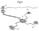
- Fig. 4 is an example of application of a laminated pipe according to the invention.
- the laminated pipe according to fig. 1 comprises an inner thermoplastic liner 1, with a layer of longitudinal glassfibres 2, a multidirectional mat 3, a radial layer of glassfibres 4, a multidirectional mat 5, a longitudinal layer of glassfibres 6, a multidirectional mat 7 and a radial layer of glassfibres 8. All these layers are bonded together with a thermoset resin.
- FIG. 1 shows a method for producing a laminated pipe according to the invention.
- the thermoplastic liner is extruded 9 and applied a longitudinal stretch. This longitudinal stretch that extends the pipe corresponds to the thermoplastic pipes thermal expansion in longitudinal direction at curing temperature.
- the thermoplastic liner achieves frozen-in tensions in longitudinal direction. These thermal tensions will later be released during curing with a positive effect on the binding conditions between the thermoset resin and the thermoplastic. Subsequent to extrusion the thermoplastic liner will be stored or fed through a bufferstation (not shown) to the production process.
- thermoplastic liner is subjected to a pre-treatment 10 consisting of washing the liner with a suitable degreasing composition such as acetone and subsequent rubbing 11 of the outer part of the liner with a rotating abrasive paper, such as a grade 40 abrasive paper.
- a suitable degreasing composition such as acetone
- a rotating abrasive paper such as a grade 40 abrasive paper.
- the liner is washed/rinsed at 12, e.g. with acetone, and fed to the production process.
- the thermoplastic liner does not come in contact with fat or contaminating materials during the abrasion/washing-process.
- This pre-treatment of the thermoplastic liner is shown at 10-12 in figur 2.
- An alternative to this pretreatment is application of a ter-polymer on the outer surface of the liner. The ter-polymer is applied with a crosshead extruder (not shown) and results in chemical bonding between
- thermoplastic liner is now ready for laminate application, which laminates are applied at room temperature.
- the laminates are directly applied to the thermoplastic liner support and this eliminates the need for an interior mandrel that are used by conventional production of laminated pipes.
- Laminated pipes are usually produced by laminating/wrapping fibres onto a rotating mandrel. By the process according to the invention neither the thermoplastic liner nor the laminate rotates.
- one layer of fibres is applied directly onto the thermoplastic liner in longitudinal direction at 13.
- the glassfibres are fed from a magazine 14 with socalled callipers and subsequently through a bath 15 containing thermoset resin, where the fibrewires are impregnated.
- the glassfibre wires are placed in a side-by-side relation and cover the thermoplastic liner completely.
- a layer of multidirectional mat 16 is applied. Outside this mat 16 another layer of radial glassfibre is applied by means of a carrousel 17. Outside this layer another multidirectional mat 18, impregnated with thermoset resin, is applied.
- This mat 18 is a thin-felt-like glassfibre mat.
- a multidirectional mat 21 is applied outside this axial layer 19. Subsequently a final layer of radial glassfibres is applied by means of a rotating carrousel 22.
- the laminate pipe is fed into a curing oven where the epoxy is cured.
- the curing oven is a pipe that is externally insulated with mineral wool. Inside the oven there is mounted a V-shaped rail on which the laminated pipe is pulled by means of a belt-conveyer 25.
- the curing oven 24 has a fan and an heating element with a controller.
- the length of the curing oven is determined according to curing time and production velocity.
- the laminated pipe is to be cured when it leaves the oven 24.
- the cellofane tapes are washed away.
- the pipe is cooled and when it has reached ambient temperature, spooled onto a drum 26. Due to the fact that the pipe has flexibility, the drum 26 is motor driven.
- a pulling wire is placed between the belts in the belt-conveyer and pulls the longitudinal fibres and the thermoplastic liner through the production process and into the curing oven 24.
- the distance between the rubber belts is increased and the conveyer 25 pulls the pipe itself.
- the production of the laminated pipe is based on a continuous process.
- the laminated pipe can be produced in infinite lengths, and it is possible to connect the pipes by known techniques if necessary. If a rupture should occur, the pipe can be connected with a steel connection after it is cured.
- thermoplastic pipe and the external loadbearing laminate achieve a mechanical and chemical binding through the production process. This binding will prevent separation of the thermoplastic liner and the laminate when the pipe is in operation.
- the mechanical binding between the thermoplastic liner and the laminate is achieved by the mechanical rubbing and surface rinsing with a degreasing composition prior to lamination and a chemical binding (grafting) between the thermoplastic liner and the curing substance in the thermoset resin.
- the heat produced in the curing oven will after some time be transferred from the laminate to the thermoplastic liner. Due to the curing temperature, the thermal tensions in the liner will be released and the liner will contract in longitudinal direction in a ratio corresponding to the extension of the pipe if it had not been subjected to tension during extrusion.
- thermoplastic liner The real extension of the thermoplastic liner in longitudinal direction is approximately zero.
- the thermoplastic liner When the curable material starts to cure, the thermoplastic liner is stabilized and the thermoset resin will form mechanical and chemical bonds to the surface of the thermoplastic liner.
- the temperature When the laminated pipe leaves the curing oven, the temperature will decrease and the thermoset resin and the liner will contract.
- the thermal treatment reduces the frozen-in tensions in the thermoplastic liner.
- the result of the applied axial tension to the thermoplastic liner is that the liner will have a minor plastic deformation when the curing process is complete and the temperature has decreased to ambient temperature. This will give a better binding between the thermoplastic and the thermoset resin and the permanent shear stress will be minimized. Thereby the shear stress between thermoset resin and thermoplastic will decrease.
- the laminated pipe is subjected to a number of different stress and load during production, transport, installation and operation.
- the composition of the composite laminate is based on the physical and environmental conditions that occur during production and the pipes lifetime.
- the composition of the pipes can of course differ from the embodiments depicted in figs. 1 and 2.
- the number of layers and their directions can be varied.
- Fig. 3 shows a connection device comprising a steel pipe 27 with an inner cone 28 that is attached to a corresponding external cone 28 on the composite pipe.
- the steel pipe 27 has a slotted section 29 at the cone's 28 largest diameter, which section reduces the tensions at the intermediate section between the composite pipe 30 and the steel pipe 27 during operation.
- a pipe adapter 31 with a cone 32, which least diameter corresponds to the inner diameter of the thermoplastic liner is pushed into the thermoplastic liner 33. This cone will force the thermoplastic liner outwards and it will be attached to the inner surface 34 of the steel pipe simultaneously like the laminated pipe.
- the pipe adapter 31 will replace the function of the thermoplastic pipe and in addition the adhesive and the laminate will not be exposed to the transported fluid.
- the pipe adapter 31 is connected to the inner surface of the steel pipe, which is threaded, where two conical surfaces abut and form a primary contact surface.
- the connection device can connect the laminated pipe to any other piping by suitable design of the other end of the pipe adapter.
- the adhesive can be a sand-containing thermoset resin.
- Fig. 4 illustrates an example of operation of a laminated pipe according to the invention between a host platform 37 and underwater installations, such as satellites 38, 39.
- the laminated pipe is spooled onto a drum and transported by a conventional laying vessel (cable laying vessel) to the installation site, connected to a oilproducing platform and laid in a predetermined route. If necessary the pipe can be dug into the seabed during laying.
- the other end of the laminated pipe is connected to a predetermined underwater installation (sub-sea template).
- Sections of laminated pipes can be joined with metallic connections wherever necessary during installation.
- the metallic connections are adhered to the laminated pipe.
- the laminated pipe can transport chemicals and/or water for injections into a transportline for oil through a Christmas tree.
- the chemicals will follow the oilflow in the flowline back to the host platform while water is injected into the well to enhance the oil recovery.
- the laminated pipe can also transport oil/fuel as a flowline.
- the laminated pipe also has many applications on-shore.
- the pipe can be installed without digging in areas where there are low risks for physical damage or environmental influence.
- the pipe can if necessary be insulated with a fire-proof coating in areas with fire hazard.
- the laminated pipe can be used for injection of water and transport of crude oil from the well to a storage site.
Landscapes
- Engineering & Computer Science (AREA)
- Mechanical Engineering (AREA)
- General Engineering & Computer Science (AREA)
- Manufacturing & Machinery (AREA)
- Rigid Pipes And Flexible Pipes (AREA)
- Laminated Bodies (AREA)
- Ceramic Capacitors (AREA)
- External Artificial Organs (AREA)
- Materials For Medical Uses (AREA)
- Lining Or Joining Of Plastics Or The Like (AREA)
Claims (5)
- Mehrschichtiges Rohr für die Offshore-Ölförderung mit einem thermoplastischen Innenrohr, das mit einem Schichtstoff aus Trägermaterial beschichtet ist, das eine Vielzahl von Schichten aus Verstärkungsfasern umfaßt, die aus der Glasfasern, Kohlefasern und polymere Fasern oder Kombinationen daraus umfassenden Gruppe gewählt sind, wobei das Trägermaterial ein wärmehärtbares Harz ist, bei dem das thermoplastische Innenrohr (1) mit einer Schicht aus längsgerichteten Verstärkungsfasern (2), einer mehrdimensionalen Matte (3), einer Schicht aus radialgerichteten Verstärkungsfasern (4), einer mehrdimensionalen Verstärkungsmatte (5), längsgerichteten Verstärkungsfasern (6), einer mehrdimensionalen Matte (7) und radialgerichteten Verstärkungsfasern (8) beschichtet worden ist und alle Schichten durch das wärmehärtbare Harz miteinander verbunden sind.
- Verfahren zum Herstellen eines mehrschichtigen Rohres, bei dem ein thermoplastisches Rohr (1) als Träger für das anschließende Ausbilden des Schichtstoffes bereitgestellt und vor der Beschichtung einer Spannung in axialer Richtung ausgesetzt wird, wodurch das Rohr entsprechend der Wärmedehnung in axialer Richtung eines spannungsfreien thermoplastischen Rohres bei der Aushärttemperatur auf eine solche Weise gedehnt wird, daß die Wärmedehnung des thermoplastischen Rohres während des Aushärtprozesses etwa Null sein wird, wonach das Rohr (1) in der angegebenen Reihenfolge mit einer Schicht aus längsgerichteten Verstärkungsfasern (2), einer mehrdimensionalen Matte (3), einer Schicht aus radialgerichteten Verstärkungsfasern (4), einer mehrdimensionalen Verstärkungsmatte (5), längsgerichteten Verstärkungsfasern (6), einer mehrdimensionalen Matte (7) und radialgerichteten Verstärkungsfasern (8) beschichtet wird, das mehrschichtige Rohr dann mit zwei Schichten Zellophanband umwickelt und anschließend in einen Aushärteofen eingebracht wird, in dem alle Schichten durch das wärmehärtbare Harz miteinander verbunden werden, wobei die Fasern aus der Glasfasern, Kohlefasern und polymere Fasern oder Kombinationen daraus umfassenden Gruppe gewählt sind.
- Verfahren nach Anspruch 2, dadurch gekennzeichnet, daß auf das thermoplastische Rohr vor der Beschichtung ein trimeres Polymer mittels eines Querkopf-Extruders aufgebracht wird, das eine chemische Verbindung zwischen dem wärmehärtbaren Harz und dem thermoplastischen Rohr herstellt.
- Verfahren zum Herstellen eines mehrschichtigen Rohrs nach Anspruch 2 oder 3, dadurch gekennzeichnet, daß das Rohr in kontinuierlichen Längen unter kontinuierlichem Auftrag verstärkender Fasern hergestellt wird, wobei das Rohr biegsam ist, so daß es nach der Herstellung auf eine Trommel aufgewickelt werden kann.
- Einsatz eines mehrschichtigen Rohrs nach Anspruch 1, bei dem das Rohr zum Transport von Chemikalien oder zum Übertragen hydraulischer Signale unter Wasser verwendet wird.
Applications Claiming Priority (3)
| Application Number | Priority Date | Filing Date | Title |
|---|---|---|---|
| NO912103 | 1991-05-31 | ||
| NO912103A NO175550C (no) | 1991-05-31 | 1991-05-31 | Fremgangsmåte ved fremstilling av laminatrör |
| PCT/NO1992/000097 WO1992021908A1 (en) | 1991-05-31 | 1992-05-27 | Laminated pipe and a process for making the same |
Publications (2)
| Publication Number | Publication Date |
|---|---|
| EP0587660A1 EP0587660A1 (de) | 1994-03-23 |
| EP0587660B1 true EP0587660B1 (de) | 1996-10-16 |
Family
ID=19894179
Family Applications (1)
| Application Number | Title | Priority Date | Filing Date |
|---|---|---|---|
| EP92911407A Expired - Lifetime EP0587660B1 (de) | 1991-05-31 | 1992-05-27 | Mehrschichtiges rohr und verfahren zu seiner herstellung |
Country Status (7)
| Country | Link |
|---|---|
| EP (1) | EP0587660B1 (de) |
| AT (1) | ATE144313T1 (de) |
| AU (1) | AU1925292A (de) |
| DE (1) | DE69214645T2 (de) |
| DK (1) | DK0587660T3 (de) |
| NO (1) | NO175550C (de) |
| WO (1) | WO1992021908A1 (de) |
Families Citing this family (15)
| Publication number | Priority date | Publication date | Assignee | Title |
|---|---|---|---|---|
| ATE182205T1 (de) * | 1995-04-03 | 1999-07-15 | Uponor Bv | Rohrverbindung und verfahren zur seiner herstellung |
| GB2319576B (en) | 1996-11-20 | 2001-02-07 | Uponor Bv | Pipe connector |
| RU2201550C2 (ru) * | 2000-10-23 | 2003-03-27 | Кашин Сергей Михайлович | Отвод из композиционного материала и способ его изготовления |
| DE20106915U1 (de) * | 2001-04-20 | 2002-08-29 | Franz Viegener II GmbH & Co. KG, 57439 Attendorn | Rohr, insbesondere Kunststoff- oder Verbundrohr |
| US20030087052A1 (en) * | 2001-11-05 | 2003-05-08 | Wideman Thomas W. | Spoolable composite tubing with a catalytically cured matrix |
| WO2003083338A1 (en) | 2002-03-29 | 2003-10-09 | Fiberspar Corporation | Systems and methods for pipeline rehabilitation |
| CA2490176C (en) | 2004-02-27 | 2013-02-05 | Fiberspar Corporation | Fiber reinforced spoolable pipe |
| WO2007104826A1 (en) * | 2006-03-13 | 2007-09-20 | Jaemiae Aulis | A method for producing a tube reinforced by means of fibres |
| CA2641492C (en) | 2007-10-23 | 2016-07-05 | Fiberspar Corporation | Heated pipe and methods of transporting viscous fluid |
| CA2690926C (en) | 2009-01-23 | 2018-03-06 | Fiberspar Corporation | Downhole fluid separation |
| EP2233811A3 (de) * | 2009-03-24 | 2011-05-25 | Poloplast GmbH & Co. KG | Kunststoffrohr |
| US8955599B2 (en) | 2009-12-15 | 2015-02-17 | Fiberspar Corporation | System and methods for removing fluids from a subterranean well |
| US9206676B2 (en) | 2009-12-15 | 2015-12-08 | Fiberspar Corporation | System and methods for removing fluids from a subterranean well |
| US9890880B2 (en) | 2012-08-10 | 2018-02-13 | National Oilwell Varco, L.P. | Composite coiled tubing connectors |
| CN111655449B (zh) * | 2017-12-29 | 2023-02-17 | 欧文斯科宁知识产权资产有限公司 | 管道绝热件以及用于制造管道绝热件的方法和系统 |
Family Cites Families (5)
| Publication number | Priority date | Publication date | Assignee | Title |
|---|---|---|---|---|
| US1358633A (en) * | 1919-01-02 | 1920-11-09 | David M Hutchinson | Hose-mender |
| NL6713324A (de) * | 1967-09-29 | 1969-04-01 | ||
| JPS5418708B2 (de) * | 1974-11-06 | 1979-07-10 | ||
| DE3121241C2 (de) * | 1980-05-28 | 1984-07-19 | Dainippon Ink And Chemicals, Inc., Tokio/Tokyo | Verfahren zum Herstellen eines Verbundkunststoffrohres aus thermoplastischem Harz |
| DE3528629A1 (de) * | 1985-08-09 | 1987-02-12 | Man Technologie Gmbh | Verfahren zur herstellung eines rotorrohres |
-
1991
- 1991-05-31 NO NO912103A patent/NO175550C/no not_active IP Right Cessation
-
1992
- 1992-05-27 EP EP92911407A patent/EP0587660B1/de not_active Expired - Lifetime
- 1992-05-27 AT AT92911407T patent/ATE144313T1/de not_active IP Right Cessation
- 1992-05-27 WO PCT/NO1992/000097 patent/WO1992021908A1/en not_active Ceased
- 1992-05-27 AU AU19252/92A patent/AU1925292A/en not_active Abandoned
- 1992-05-27 DE DE69214645T patent/DE69214645T2/de not_active Expired - Fee Related
- 1992-05-27 DK DK92911407.2T patent/DK0587660T3/da active
Also Published As
| Publication number | Publication date |
|---|---|
| WO1992021908A1 (en) | 1992-12-10 |
| DK0587660T3 (da) | 1996-11-18 |
| NO912103D0 (no) | 1991-05-31 |
| DE69214645D1 (de) | 1996-11-21 |
| NO175550C (no) | 1997-05-02 |
| NO175550B (no) | 1994-07-18 |
| ATE144313T1 (de) | 1996-11-15 |
| DE69214645T2 (de) | 1997-02-20 |
| NO912103L (no) | 1992-12-01 |
| AU1925292A (en) | 1993-01-08 |
| EP0587660A1 (de) | 1994-03-23 |
Similar Documents
| Publication | Publication Date | Title |
|---|---|---|
| US5755266A (en) | Laminated pipe for offshore oil production, including sequential layers of reinforcing fibers and fiber mat in cured matrix of plastic resin, on thermoplastic liner tube | |
| US5913337A (en) | Spoolable composite tubular member with energy conductors | |
| WO1992021908A1 (en) | Laminated pipe and a process for making the same | |
| US8066033B2 (en) | Composite spoolable tube | |
| EP2688727B1 (de) | Verfahren zur herstellung eines biegsamen rohrkörpers, sowie ein danach hergestellter rohrkörper | |
| US8678043B2 (en) | Method for repairing and strengthening pipe with internal helically wound tensile reinforcement | |
| US5236018A (en) | Boring casing for boring machines | |
| US7096890B2 (en) | Inversion liner and liner components for conduits | |
| EP1090243B1 (de) | Biegsames verbundwerkstoffrohr und verfahren zu seiner herstellung | |
| US20120155813A1 (en) | Composite Spoolable Tube | |
| US7234410B2 (en) | Buoyancy control systems for tubes | |
| AU2016221437B2 (en) | Subsea pipe-in-pipe structures | |
| US20220146026A1 (en) | Potted pipe fitting systems and methods | |
| EP3596374A1 (de) | Verbindungs- und kathodischer schutz | |
| US10436350B1 (en) | Trenchless pipe-laying | |
| US11746546B1 (en) | External onsite-manufactured continuous structural sleeve | |
| CN204785138U (zh) | 集束连续管 | |
| US11428350B2 (en) | Pipe reinforcement strip anchoring systems and methods |
Legal Events
| Date | Code | Title | Description |
|---|---|---|---|
| PUAI | Public reference made under article 153(3) epc to a published international application that has entered the european phase |
Free format text: ORIGINAL CODE: 0009012 |
|
| 17P | Request for examination filed |
Effective date: 19931126 |
|
| AK | Designated contracting states |
Kind code of ref document: A1 Designated state(s): AT BE CH DE DK ES FR GB GR IT LI LU MC NL SE |
|
| 17Q | First examination report despatched |
Effective date: 19950505 |
|
| GRAH | Despatch of communication of intention to grant a patent |
Free format text: ORIGINAL CODE: EPIDOS IGRA |
|
| GRAH | Despatch of communication of intention to grant a patent |
Free format text: ORIGINAL CODE: EPIDOS IGRA |
|
| GRAA | (expected) grant |
Free format text: ORIGINAL CODE: 0009210 |
|
| RAP1 | Party data changed (applicant data changed or rights of an application transferred) |
Owner name: COMPIPE A/S |
|
| AK | Designated contracting states |
Kind code of ref document: B1 Designated state(s): AT BE CH DE DK ES FR GB GR IT LI LU MC NL SE |
|
| PG25 | Lapsed in a contracting state [announced via postgrant information from national office to epo] |
Ref country code: LI Effective date: 19961016 Ref country code: GR Free format text: LAPSE BECAUSE OF FAILURE TO SUBMIT A TRANSLATION OF THE DESCRIPTION OR TO PAY THE FEE WITHIN THE PRESCRIBED TIME-LIMIT Effective date: 19961016 Ref country code: ES Free format text: THE PATENT HAS BEEN ANNULLED BY A DECISION OF A NATIONAL AUTHORITY Effective date: 19961016 Ref country code: CH Effective date: 19961016 Ref country code: BE Effective date: 19961016 Ref country code: AT Effective date: 19961016 |
|
| REF | Corresponds to: |
Ref document number: 144313 Country of ref document: AT Date of ref document: 19961115 Kind code of ref document: T |
|
| ITF | It: translation for a ep patent filed | ||
| REG | Reference to a national code |
Ref country code: DK Ref legal event code: T3 |
|
| REF | Corresponds to: |
Ref document number: 69214645 Country of ref document: DE Date of ref document: 19961121 |
|
| ET | Fr: translation filed | ||
| REG | Reference to a national code |
Ref country code: CH Ref legal event code: PL |
|
| PG25 | Lapsed in a contracting state [announced via postgrant information from national office to epo] |
Ref country code: LU Free format text: LAPSE BECAUSE OF NON-PAYMENT OF DUE FEES Effective date: 19970531 |
|
| PLBE | No opposition filed within time limit |
Free format text: ORIGINAL CODE: 0009261 |
|
| STAA | Information on the status of an ep patent application or granted ep patent |
Free format text: STATUS: NO OPPOSITION FILED WITHIN TIME LIMIT |
|
| 26N | No opposition filed | ||
| PG25 | Lapsed in a contracting state [announced via postgrant information from national office to epo] |
Ref country code: MC Effective date: 19971130 |
|
| PGFP | Annual fee paid to national office [announced via postgrant information from national office to epo] |
Ref country code: GB Payment date: 20011123 Year of fee payment: 10 |
|
| PGFP | Annual fee paid to national office [announced via postgrant information from national office to epo] |
Ref country code: SE Payment date: 20011126 Year of fee payment: 10 |
|
| PGFP | Annual fee paid to national office [announced via postgrant information from national office to epo] |
Ref country code: NL Payment date: 20011130 Year of fee payment: 10 Ref country code: FR Payment date: 20011130 Year of fee payment: 10 Ref country code: DK Payment date: 20011130 Year of fee payment: 10 Ref country code: DE Payment date: 20011130 Year of fee payment: 10 |
|
| REG | Reference to a national code |
Ref country code: GB Ref legal event code: IF02 |
|
| PG25 | Lapsed in a contracting state [announced via postgrant information from national office to epo] |
Ref country code: GB Free format text: LAPSE BECAUSE OF NON-PAYMENT OF DUE FEES Effective date: 20020527 |
|
| PG25 | Lapsed in a contracting state [announced via postgrant information from national office to epo] |
Ref country code: SE Free format text: LAPSE BECAUSE OF NON-PAYMENT OF DUE FEES Effective date: 20020528 |
|
| PG25 | Lapsed in a contracting state [announced via postgrant information from national office to epo] |
Ref country code: DK Free format text: LAPSE BECAUSE OF NON-PAYMENT OF DUE FEES Effective date: 20020531 |
|
| PG25 | Lapsed in a contracting state [announced via postgrant information from national office to epo] |
Ref country code: NL Free format text: LAPSE BECAUSE OF NON-PAYMENT OF DUE FEES Effective date: 20021201 |
|
| PG25 | Lapsed in a contracting state [announced via postgrant information from national office to epo] |
Ref country code: DE Free format text: LAPSE BECAUSE OF NON-PAYMENT OF DUE FEES Effective date: 20021203 |
|
| REG | Reference to a national code |
Ref country code: DK Ref legal event code: EBP |
|
| EUG | Se: european patent has lapsed | ||
| GBPC | Gb: european patent ceased through non-payment of renewal fee |
Effective date: 20020527 |
|
| NLV4 | Nl: lapsed or anulled due to non-payment of the annual fee |
Effective date: 20021201 |
|
| PG25 | Lapsed in a contracting state [announced via postgrant information from national office to epo] |
Ref country code: FR Free format text: LAPSE BECAUSE OF NON-PAYMENT OF DUE FEES Effective date: 20030331 |
|
| REG | Reference to a national code |
Ref country code: FR Ref legal event code: ST |
|
| PG25 | Lapsed in a contracting state [announced via postgrant information from national office to epo] |
Ref country code: IT Free format text: LAPSE BECAUSE OF NON-PAYMENT OF DUE FEES Effective date: 20050527 |
|
| PG25 | Lapsed in a contracting state [announced via postgrant information from national office to epo] |
Ref country code: FR Free format text: LAPSE BECAUSE OF NON-PAYMENT OF DUE FEES Effective date: 20020531 |