EP0587733B1 - Digitale Filterbank mit niedriger Rechenkomplexität - Google Patents
Digitale Filterbank mit niedriger Rechenkomplexität Download PDFInfo
- Publication number
- EP0587733B1 EP0587733B1 EP92912812A EP92912812A EP0587733B1 EP 0587733 B1 EP0587733 B1 EP 0587733B1 EP 92912812 A EP92912812 A EP 92912812A EP 92912812 A EP92912812 A EP 92912812A EP 0587733 B1 EP0587733 B1 EP 0587733B1
- Authority
- EP
- European Patent Office
- Prior art keywords
- transform
- domain
- time
- coefficients
- inverse
- Prior art date
- Legal status (The legal status is an assumption and is not a legal conclusion. Google has not performed a legal analysis and makes no representation as to the accuracy of the status listed.)
- Expired - Lifetime
Links
Images





Classifications
-
- G—PHYSICS
- G06—COMPUTING OR CALCULATING; COUNTING
- G06T—IMAGE DATA PROCESSING OR GENERATION, IN GENERAL
- G06T9/00—Image coding
- G06T9/005—Statistical coding, e.g. Huffman, run length coding
-
- G—PHYSICS
- G10—MUSICAL INSTRUMENTS; ACOUSTICS
- G10L—SPEECH ANALYSIS TECHNIQUES OR SPEECH SYNTHESIS; SPEECH RECOGNITION; SPEECH OR VOICE PROCESSING TECHNIQUES; SPEECH OR AUDIO CODING OR DECODING
- G10L19/00—Speech or audio signals analysis-synthesis techniques for redundancy reduction, e.g. in vocoders; Coding or decoding of speech or audio signals, using source filter models or psychoacoustic analysis
- G10L19/02—Speech or audio signals analysis-synthesis techniques for redundancy reduction, e.g. in vocoders; Coding or decoding of speech or audio signals, using source filter models or psychoacoustic analysis using spectral analysis, e.g. transform vocoders or subband vocoders
- G10L19/0204—Speech or audio signals analysis-synthesis techniques for redundancy reduction, e.g. in vocoders; Coding or decoding of speech or audio signals, using source filter models or psychoacoustic analysis using spectral analysis, e.g. transform vocoders or subband vocoders using subband decomposition
-
- H—ELECTRICITY
- H03—ELECTRONIC CIRCUITRY
- H03H—IMPEDANCE NETWORKS, e.g. RESONANT CIRCUITS; RESONATORS
- H03H17/00—Networks using digital techniques
- H03H17/02—Frequency selective networks
- H03H17/0248—Filters characterised by a particular frequency response or filtering method
- H03H17/0264—Filter sets with mutual related characteristics
- H03H17/0266—Filter banks
-
- H—ELECTRICITY
- H04—ELECTRIC COMMUNICATION TECHNIQUE
- H04B—TRANSMISSION
- H04B1/00—Details of transmission systems, not covered by a single one of groups H04B3/00 - H04B13/00; Details of transmission systems not characterised by the medium used for transmission
- H04B1/66—Details of transmission systems, not covered by a single one of groups H04B3/00 - H04B13/00; Details of transmission systems not characterised by the medium used for transmission for reducing bandwidth of signals; for improving efficiency of transmission
-
- H—ELECTRICITY
- H04—ELECTRIC COMMUNICATION TECHNIQUE
- H04B—TRANSMISSION
- H04B1/00—Details of transmission systems, not covered by a single one of groups H04B3/00 - H04B13/00; Details of transmission systems not characterised by the medium used for transmission
- H04B1/66—Details of transmission systems, not covered by a single one of groups H04B3/00 - H04B13/00; Details of transmission systems not characterised by the medium used for transmission for reducing bandwidth of signals; for improving efficiency of transmission
- H04B1/665—Details of transmission systems, not covered by a single one of groups H04B3/00 - H04B13/00; Details of transmission systems not characterised by the medium used for transmission for reducing bandwidth of signals; for improving efficiency of transmission using psychoacoustic properties of the ear, e.g. masking effect
Definitions
- the invention relates in general to digital encoding and decoding of information. More particularly, the invention relates to efficient implementation of digital analysis and synthesis filter banks used in digital encoding and decoding.
- the length of the filter bank used to implement critically-sampled analysis and synthesis filter banks may be adaptively selected.
- Improving coding efficiency includes (1) reducing informational requirements, that is, reducing the amount of information required to adequately represent a signal during transmission or storage, and (2) reducing processing requirements, that is, reducing the amount of processing required to implement the encoding and decoding processes.
- Subband coders and transform coders can reduce the informational requirements in particular frequency bands where the noise caused by the resulting coding inaccuracy is psychoacoustically masked.
- Subband coders may be implemented by a bank of digital bandpass filters defining subbands of varying bandwidth.
- Transform coders may be implemented by any of several time-domain to frequency-domain transforms. One or more adjacent transform coefficients are grouped together to define "subbands" having effective bandwidths which are sums of individual transform coefficient bandwidths.
- processing requirements can be reduced by increasing the efficiency of subband filtering.
- Improved processing efficiency permits implementation of encoders and decoders which are less expensive to build, or which impose lower signal propagation delays through an encoder/decoder system.
- the analysis and synthesis filter banks are implemented by discrete time-domain to frequency-domain transforms such as the Discrete Fourier Transform (DFT), the Discrete Cosine Transform (DCT), and the Discrete Sine Transform (DST).
- DFT Discrete Fourier Transform
- DCT Discrete Cosine Transform
- DST Discrete Sine Transform
- the number of time domain signal samples, referred to herein as the time-domain signal sample block length, processed by such transforms is sometimes called the transform length, and the amount of processing required to perform these transforms is generally proportional to the square of the time-domain signal sample block length.
- the number of frequency-domain transform coefficients generated by a transform is also sometimes called the transform length. It is common for the number of frequency-domain transform coefficients generated by the transform to be equal to the time-domain signal sample block length, but this equality is not necessary.
- the E-TDAC transform is sometimes described in the art as a transform of length N that transforms signal sample blocks with a length of 2 N samples. It is possible, however, to also describe the transform as one of length N which generates only 1 ⁇ 2 N unique frequency-domain transform coefficients.
- the time-domain signal sample block length and the discrete transform length are generally assumed to be synonyms.
- E-TDAC Evenly-stacked Time-Domain Aliasing Cancellation
- Malvar "Lapped Transforms for Efficient Transform/Subband Coding," IEEE Trans. Acoust., Speech, Signal Proc., ASSP-38, June, 1980, pp. 969-78.
- This technique implements an N -point modified DCT by performing a 1 ⁇ 2 N -point DST after combining pairs of the samples representing the input signal, or "folding" the N input signal samples into a smaller set of 1 ⁇ 2 N points. It is approximately twice as efficient as performing the modified DCT in a straight-forward manner; however, Malvar only teaches how to fold input samples for a filter bank implemented by one specific modified DCT whose input samples have been weighted by a specific sine-tapered analysis window.
- time-domain signal sample block lengths degrade the time-resolution of a subband filter bank. Inadequate time-resolution can produce audible distortion artifacts when quantizing errors of signal events, such as transients, producing pre-transient and post-transient ringing which exceed the ear's temporal psychoacoustic masking interval. Hence, it is desirable that techniques which improve subband filter bank processing efficiency should also permit adaptive selection of the time-domain signal sample block length.
- an encoder provides for the encoding of input signal samples representing a time-domain signal.
- the input samples which are weighted by an analysis-window function are buffered into time-domain signal sample blocks. Pairs of signal samples in the time-domain signal sample blocks are combined by a forward pre-transform function to generate modified samples.
- Frequency-domain transform coefficients are generated by applying a discrete digital transform to the modified samples.
- Spectral information is generated by applying a forward post-transform function to the frequency-domain transform coefficients.
- a decoder provides for the decoding of digitally encoded spectral information.
- Frequency-domain transform coefficients are generated by applying an inverse pre-transform function to the spectral information.
- Time-domain transform coefficients are generated by applying an inverse discrete digital transform to the frequency-domain transform coefficients.
- Time-domain signal sample blocks are generated by applying an inverse post-transform function to the time-domain transform coefficients, and output samples which correspond to the input samples to a companion encoder are generated by overlapping and adding samples in adjacent time-domain signal sample blocks.
- Figure 1 is a functional block diagram illustrating the basic functional structure of an encoder incorporating a preferred embodiment of the present invention.
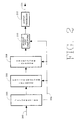
- Figure 2 is a functional block diagram illustrating the basic functional structure of a decoder incorporating a preferred embodiment of the present invention.
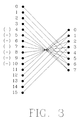
- Figure 3 is a flowgraph illustrating the forward pre-transform function applied to a 16-sample time-domain signal sample block to form an 8-sample modified sample block for a basic embodiment of the present invention permitting implementation of an E-TDAC transform analysis filter bank by a DCT and DST.
- Figure 4 is a flowgraph illustrating the forward pre-transform function applied to a 16-sample time-domain signal sample block to form an 8-sample modified sample block for an alternative embodiment of the present invention permitting implementation of an E-TDAC transform analysis filter bank by a DFT.
- Figure 5 is a hypothetical graphical representation illustrating the time-reversal regions of the time-domain aliasing component created by the E-TDAC transform using the conventional TDAC phase term.
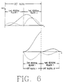
- Figure 6 is a hypothetical graphical representation illustrating the time-reversal regions of the time-domain aliasing component created by the E-TDAC transform using the TDAC phase term required to cancel time-domain aliasing in an N-sample length block overlapped with a subsequent 1 ⁇ 2 N -sample length block.
- Figure 7 is a hypothetical graphical representation illustrating the boundary between time-reversal regions of the time-domain aliasing component in a 1 ⁇ 4 N -sample length block.
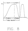
- Figure 8 is a hypothetical graphical representation of a bridge transform illustrating the time-reversal regions of the time-domain aliasing component.
- Figure 9 is a flowgraph illustrating the forward pre-transform function applied to a 16-sample time-domain signal sample block to form an 8-sample modified sample block permitting implementation of an adaptive-length E-TDAC transform analysis filter bank by a DCT and DST.
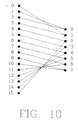
- Figure 10 is a flowgraph illustrating the forward pre-transform function applied to a 16-sample time-domain signal sample block to form an 8-sample modified sample block permitting implementation of an adaptive-length O-TDAC transform analysis filter bank by a DST.
- FIG. 1 illustrates the basic functional structure of a transform-based encoder incorporating an embodiment of the present invention.
- an encoder comprises buffer 102 which buffers input samples received from input path 100 into time-domain signal sample blocks, forward pre-transform 106 which generates modified samples by combining pairs of signal samples received from buffer 102 and in response to information received from path 104 establishing the number of signal samples constituting a time-domain signal sample block, forward transform 108 Which transforms the modified samples into frequency-domain transform coefficients by applying a transform whose length is adapted in response to information received from path 104, forward post-transform 110 which generates spectral information from the frequency-domain transform coefficients and in response to the information received from path 104, and formatter 112 which assembles digital information including the spectral information into a form suitable for transmission or storage along path 114.
- the functions performed by buffer 102 and formatter 112 are not discussed in detail herein.
- Figure 2 illustrates the basic functional structure of a transform-based decoder incorporating an embodiment of the present invention.
- a decoder comprises deformatter 202 which extracts spectral information and information establishing the inverse transform length from the encoded digital signal received from path 200, inverse pre-transform 206 which generates frequency-domain transform coefficients from the extracted spectral information and in response to the information establishing the inverse transform length received along path 204, inverse transform 208 which transforms the frequency-domain transform coefficients into time-domain transform coefficients by applying a transform whose length is in response to information received from path 204, inverse post-transform 210 which generates signal samples from the time-domain transform coefficients and in response to information received from path 204, and output processor 212 which generates along path 214 output samples corresponding to the input samples to a companion encoder in response to the signal samples.
- the functions performed by deformatter 202 and output processor 212 are not discussed in detail herein.
- a basic embodiment of the present invention is introduced in some detail before alternative embodiments are discussed.
- This basic embodiment uses fixed-length E-TDAC transforms to implement the analysis and synthesis filter banks. Preferred embodiments of various features are described throughout the discussion.
- a buffer represented by box 102 in Figure 1, receives signal samples and groups them into a sequence of time-domain signal sample blocks. Each block comprises N signal samples.
- the signal samples may be received from the sampling of an analog signal, from the generation of samples representing or simulating an analog signal, or from any other source of discrete-valued samples which correspond to a time-domain signal.
- filter selectivity may be affected significantly by weighting the time-domain signal samples by a weighting function commonly called a window. See generally, Harris, “On the Use of Windows for Harmonic Analysis with the Discrete Fourier Transform," Proc. IEEE , vol. 66, January, 1978, pp. 51-83.
- the E-TDAC transform used in the basic embodiment of the present invention requires window weighting, both weighting of the time-domain signal samples in an encoder prior to forward transform filtering, referred to as analysis windowing, and weighting of the recovered time-domain signal samples in a decoder after inverse transform filtering, referred to as synthesis windowing.
- analysis windowing weighting of the time-domain signal samples in an encoder prior to forward transform filtering
- synthesis windowing weighting of the recovered time-domain signal samples in a decoder after inverse transform filtering
- the forward transform is represented by box 108 in Figure 1.
- the E-TDAC transform used in the basic embodiment of the present invention is equivalent to the alternate application of a Modified Discrete Cosine Transform (MDCT) with a Modified Discrete Sine Transform (MDST).
- MDCT Modified Discrete Cosine Transform
- MDST Modified Discrete Sine Transform
- Each set of coefficients generated by the MDCT and the MDST are referred to herein as MDCT coefficient sets and MDST coefficient sets, respectively.
- the E-TDAC technique can accurately recover an input signal from an alternating sequence of overlapped fixed-length MDCT coefficient sets and MDST coefficient sets of the form ⁇ C(k) ⁇ 0 , ⁇ S(k) ⁇ 1 , ⁇ C(k) ⁇ 2 , ⁇ S(k) ⁇ 3 ,....
- the phase term m in equations 1 and 2 controls the phase shift of the time-domain aliasing distortion.
- E-TDAC requires the aliasing to be as follows: for the MDCT, the time-domain alias component consists of the first half of the sampled and windowed signal reversed in time about the one-quarter point of the sample block and the second half of the sampled and windowed signal reversed in time about the three-quarter point of the sample block; for the MDST, the alias component is similar to that for the MDCT except its amplitude is inverted in sign.
- the processing requirements of the technique used to evaluate the MDCT and the MDST may be reduced by applying a forward pre-transform function to the time-domain signal sample blocks to produce blocks of modified samples, and applying a 1 ⁇ 2 N -point DCT and a 1 ⁇ 2 N -point DST to the modified sample blocks for the N -point MDCT and MDST, respectively.
- the forward pre-transform function is represented by box 106 in Figure 1.
- the pre-transform function combines pairs of signal samples in each time-domain signal sample block of length N to produce a block of modified samples of length 1 ⁇ 2 N .
- Equation 1 The mathematical basis for using a 1 ⁇ 2 N -point DCT applied to modified samples to perform the N-point MDCT may be seen by first substituting equation 6 for the phase term m into equation 1.
- the MDST of length N can be implemented by a DST of length 1 ⁇ 2 N ;
- the forward pre-transform function for this basic embodiment can be performed by any of several implementations including software-controlled processors and circuits capable of combining pairs of time-domain signal samples to form modified samples.
- FIG 3 illustrates the forward pre-transform functions of equations 9 and 12 for a basic embodiment of the present invention.
- the minus signs shown within parenthesis denote terms which are subtractively combined with an associated sample for the function shown above in equation 12. This subtractive combination may be accomplished in circuitry, for example, by negating the value of the signal sample representations corresponding to the nodes in Figure 3 with minus signs in parenthesis and additively combining the resultant representations.
- the forward transform in the basic embodiment of the present generates frequency-domain transform coefficients in response to an input signal which are equivalent to the coefficients generated by an E-TDAC transform applied to the same input signal.
- Some alternative embodiments of the present invention described below require application of a forward post-transform function to the coefficients generated by the forward transform in order to obtain spectral information equivalent to transform coefficients generated by a corresponding TDAC transform.
- an encoder incorporating any embodiment of the present invention need not apply a forward post-transform function to the frequency-domain transform coefficients generated by the forward transform.
- the frequency-domain transform coefficients themselves may be directly transmitted or stored and subsequently transmitted to a corresponding receiver for decoding.
- spectral information is required.
- encoder/decoder systems which exploit psychoacoustic principles to reduce coded signal information requirements usually require spectral information in order to estimate psychoacoustic masking effects of a signal's spectral components.
- Frequency-domain transform coefficients generated by the forward transform and spectral information generated by the various forward post-transform functions described below are generally not suitable for low bit-rate transmission or efficient storage.
- Various quantization techniques may be used to reduce informational requirements by taking advantage of a signal's irrelevancy.
- the forward post-transform function represented by box 110 in Figure 1 may comprise quantizing the frequency-domain transform coefficients generated by the forward transform; however, quantizing is not required to practice the present invention.
- Output formatting represented by box 112 in Figure 1 is not required to practice the present invention but is often used in signal encoding applications. Generally, output formatting assembles the spectral information and other information required for transmission or storage. Any additional side-information needed by a decoder is also assembled into the formatted signal. Frame synchronization bits and error detection/correction codes may be used as needed for transmission. Database pointers or keys may be added as needed for storage. The formatted data is ready for transmission or for storage along path 114 shown in Figure 1.
- Input deformatting represented by box 202 in Figure 2 is not required to practice the present invention but is often used in signal decoding applications. Deformatting extracts spectral information and any side information from a formatted signal received from path 200 either by receipt of a transmitted signal or retrieved from storage.
- the inverse pre-transform function obtaineds frequency-domain transform coefficients from the spectral information in the received signal. If the spectral information in the received signal substantially corresponds to the frequency-domain transform coefficients generated by an E-TDAC transform, then the inverse pre-transform function in a basic embodiment of the present function may be a trivial or essentially null function such as, for example, grouping spectral information into blocks.
- the inverse pre-transform function may comprise dequantizing the encoded digital information into a form suitable for input to the inverse transform filter bank; however, dequantizing is not required to practice the present invention.
- Box 208 in Figure 2 represents a bank of synthesis filters which transforms each set of frequency-domain transform coefficients into time-domain transform coefficients.
- a transform inverse to that used in analysis filter bank 108 in Figure 1 implements synthesis filter bank 208.
- the inverse discrete transforms for E-TDAC used in the basic embodiment of the present invention is an alternating application of an Inverse Modified Discrete Cosine Transform (IMDCT) and an Inverse Modified Discrete Sine Transform (IMDST) shown in equations 13 and 14, respectively; where
- IMDCT Inverse Modified Discrete Cosine Transform
- IMDST Inverse Modified Discrete Sine Transform
- the processing requirements of the technique used to evaluate the IMDCT and the IMDST may be reduced by instead evaluating an Inverse DCT (IDCT) and an Inverse DST (IDST) and applying an inverse post-transform function after application of the inverse transforms.
- This inverse post-transform function is represented by box 210 in Figure 2.
- the inverse post-transform function splits time-domain transform coefficients into signal samples.
- An overlap-add process is required by the TDAC transforms to generate samples corresponding to signal samples encoded by a companion encoder. This process, represented by box 212 in Figure 2, overlaps adjacent blocks of recovered time-domain samples and adds the samples in one block to samples in the adjacent overlapped block.
- the E-TDAC transform used in the basic embodiment of the present invention also requires prior to overlap-add the application of a synthesis window to the recovered time-domain sample blocks.
- the constraints the E-TDAC transform places upon the design of the synthesis window, the analysis window, and the overlap-add process is discussed fully in the paper by Princen and Bradley referred to above.
- the forward E-TDAC transform is implemented by a Discrete Fourier Transform (DFT).
- DFT Discrete Fourier Transform
- a forward pre-transform function generates an alternating sequence of two types of blocks comprising modified samples; one block type comprising modified samples p(n) and a second block type comprising modified samples r(n). Each modified sample is formed from the combination of one pair of signal samples x(n) according to A flowgraph for a 16-sample block illustrating this forward pre-transform function is shown in Figure 4.
- the inverse E-TDAC transform is implemented by an Inverse DFT (IDFT).
- IDFT Inverse DFT
- An inverse pre-transform function recovers spectral information ⁇ (k) and ⁇ (k) corresponding to E-TDAC transform coefficients C(k) and S(k) , respectively, from the encoded signal and generates in response to the recovered spectral information an alternating sequence of two types of blocks comprising recovered frequency-domain transform coefficients; one block type comprises recovered complex-valued coefficients P ⁇ (k) of the form T ⁇ (k)+ j ⁇ (k) and a second block type comprises recovered complex-valued coefficients R ⁇ (k) of the form V ⁇ (k)+ j ⁇ (k).
- An inverse transform generates an alternating sequence of two types of blocks comprising recovered time-domain transform coefficients by applying an IDFT to the alternating sequence of frequency-domain transform coefficient blocks; one block type comprises recovered time-domain transform coefficients p ⁇ (k) and a second block type comprises recovered time-domain transform coefficients r ⁇ (k).
- the IDFT used to recover the time-domain transform coefficients is shown in equations 31 and 32;
- Recovered time-domain signal samples x ⁇ (n) are obtained by applying an inverse post-transform function to the alternating sequence of blocks comprising recovered time-domain transform coefficients.
- the MDCT and the MDST of one or more forward E-TDAC transforms are implemented concurrently by one or more DFTs.
- two adjacent frequency-domain coefficient sets as illustrated in expression 5 above may be generated concurrently by a single DFT.
- a MDCT coefficient set for channel one may be generated concurrently with a MDST coefficient set for channel two, immediately followed by a MDST coefficient set for channel one generated concurrently with a MDCT coefficient set for channel two.
- Other combinations of coefficient sets for concurrent processing are possible.
- concurrent transforms see generally, Brigham, The Fast Fourier Transform, Englewood Cliffs, NJ: Prentice-Hall, Inc., 1974, pp. 166-67.
- a forward pre-transform function generates a sequence of blocks comprising complex-valued modified samples q(n) of the form p(n)+ j ⁇ r(n) where p(n) and r(n) are formed from the application of the forward pre-transform function described above and shown in equations 21 and 22.
- the MDCT and the MDST constituting the forward E-TDAC transform are concurrently implemented by a DFT which generates complex-valued frequency-domain transform coefficients Q(k) of the form G(k)+ j ⁇ H(k) according to
- Spectral information corresponding to E-TDAC transform coefficients C(k) and S(k) is obtained by applying the forward post-transform functions according to
- the IMDCT and the IMDST of one or more inverse E-TDAC transforms are implemented concurrently by one or more IDFTs.
- the IMDCT and the IMDST constituting the inverse E-TDAC transform are concurrently implemented by an IDFT which generates complex-valued time-domain transform coefficients q ⁇ (n) of the form p ⁇ (n)+ j ⁇ r ⁇ (n) according to
- Time-domain signal samples x ⁇ (n) are recovered from the application of the inverse post-transform function described above and shown in equations 33 through 36.
- FIG. 5 is a hypothetical graphical representation of two adjacent overlapped N-sample length time-domain signal sample blocks recovered by an inverse E-TDAC transform, one block recovered from the IMDCT and the second block recovered from the IMDST after synthesis windowing but before overlap-add of the adjacent blocks has cancelled time-domain aliasing.
- the representation in this and other figures does not show individual signal samples, but rather illustrates only the envelope of the amplitude of samples within the windowed signal sample blocks.
- Each recovered signal sample block comprises two components: one component represented in the figures by a solid line substantially corresponds to the analysis- and synthesis-window weighted input signal samples, and the second component represented in the figures by a broken line corresponds to the analysis- and synthesis-window weighted time-domain aliasing distortion.
- the aliasing component is a time-reversed replica of the windowed input signal samples which occurs in two separate regions.
- the phase term m for the E-TDAC and the O-TDAC transforms controls the location of the boundary between these two regions. For fixed-length E-TDAC and O-TDAC transforms, the boundary is located at the mid-point of the signal sample block.
- the phase term required for time-domain aliasing cancellation under this condition is shown in equation 6.
- Figure 6 is a hypothetical graphical representation of three time-domain signal sample blocks recovered from an inverse E-TDAC transform prior to overlap-add.
- the first block is an N -sample length block which has been recovered from the IMDCT.
- the second and third blocks are 1 ⁇ 2 N -sample length blocks which have been recovered from the IMDST.
- the aliasing component in the N -sample length MDCT block comprises a replica of the first half of the signal sample block reversed in time about the one-quarter point of the sample block, and a replica of the second half of the sampled signal reversed in time about the three-quarter point of the sample block.
- the time-domain aliasing component in the first MDST 1 ⁇ 2 N -sample length block must be a replica of the entire 1 ⁇ 2 N -sample length block inverted in sign and time-reversed end-for-end.
- Figure 7 illustrates two window-weighted time-domain signal sample blocks.
- the right-hand block is 1 ⁇ 4 N samples in length.
- the boundary between time-reversal regions is at a point N/8 samples from the right-hand or trailing edge of the block.
- a bridge transform is a transform which bridges a shift from one transform length to another. For example, as shown in Figure 8, suppose the present invention is called upon to process one block of 1 ⁇ 2 N samples followed by another block of 1 ⁇ 4 N samples. It is possible to perform a separate transform for each block. For reasons whose explanation exceed the scope of this discussion, a bridge transform improves coder performance by instead transforming a single block of 3 / 4 N samples.
- the bridge transform required to process the 3 / 4 N -sample block shown in Figure 8 may be implemented by an FFT to compute the transform for three 1 ⁇ 4N blocks followed by a recombination operation.
- This technique is known in the art and is discussed in Oppenheim and Schafer, Digital Signal Processing , Englewood Cliffs, N.J.: Prentice-Hall, Inc., 1975, pp. 307-14.
- the FFT with this recombination operation can also be used to concurrently process two E-TDAC bridge transforms in the same manner as that briefly discussed above for fixed-length transforms. It is important to note, however, that concurrent processing in E-TDAC is possible only for a MDCT and MDST which have the same length and TDAC phase term.
- the length of the inverse transform may be established by side-information passed by the encoder in the encoded signal.
- each adaptive-length embodiment is substantially the same as that for a corresponding fixed-length embodiment.
- the most significant differences pertain to the pre- and post-transform functions and to the length and phase terms of the transform functions.
- each time-domain signal sample block is defined to be a + b samples in length, overlapping the immediately prior block by a samples and overlapping the immediately subsequent block by b samples. It is assumed that the number of samples in the two overlap intervals may vary from block to block. According to the conventions established in the previous discussion, the bridge transform applied to each time-domain signal sample block is an adaptive-length (a + b) -point transform.
- One adaptive-length embodiment corresponds to the fixed-length basic embodiment discussed above.
- the forward transform comprises a DCT and a DST according to
- the inverse transform comprises an IDCT and an IDST according to
- Another adaptive-length embodiment corresponds to the fixed-length embodiment of the E-TDAC transform implemented by a DFT, discussed above.
- the forward pre-transform corresponding to the functions shown in equations 21 and 22 for the fixed-length embodiment, generates an alternating sequence of modified sample blocks according to
- the forward E-TDAC transform is implemented by a DFT which generates alternating sets of complex-valued frequency-domain transform coefficients P(k) of the form T(k) +j ⁇ U(k) and R(k) of the form V(k) +j ⁇ W(k) in response to the alternating sequence of modified sample blocks according to
- the inverse pre-transform function corresponding to the functions shown in equations 27 through 30 for the fixed-length embodiment, generates an alternating sequence of blocks comprising recovered frequency-domain transform coefficients; one block type comprises recovered complex-valued coefficients P ⁇ (k) of the form T ⁇ (k)+ j ⁇ (k) and a second block type comprises recovered complex-valued coefficients R ⁇ (k) of the form V ⁇ (k)+ j ⁇ (k).
- the inverse transform generates an alternating sequence of two types of blocks comprising recovered time-domain transform coefficients by applying an IDFT to the alternating sequence of frequency-domain transform coefficient blocks; one block type comprises recovered time-domain transform coefficients p ⁇ (k) and a second block type comprises recovered time-domain transform coefficients r ⁇ (k) .
- the IDFT used to obtain the recovered time-domain transform coefficients is shown in equations 64 and 65;
- the processing requirements needed to implement this transform can be reduced by applying a forward pre-transform function to the time-domain signal samples to generate modified samples e(n), then applying a DST to the modified samples to generate frequency-domain transform coefficients X(k) .
- the forward transform comprises a DST according to
Landscapes
- Engineering & Computer Science (AREA)
- Physics & Mathematics (AREA)
- Signal Processing (AREA)
- Computer Networks & Wireless Communication (AREA)
- Multimedia (AREA)
- Acoustics & Sound (AREA)
- Theoretical Computer Science (AREA)
- Human Computer Interaction (AREA)
- Health & Medical Sciences (AREA)
- Computational Linguistics (AREA)
- Spectroscopy & Molecular Physics (AREA)
- General Physics & Mathematics (AREA)
- Audiology, Speech & Language Pathology (AREA)
- Computer Hardware Design (AREA)
- Mathematical Physics (AREA)
- Compression, Expansion, Code Conversion, And Decoders (AREA)
- Complex Calculations (AREA)
- Networks Using Active Elements (AREA)
- Signal Processing For Digital Recording And Reproducing (AREA)
Claims (17)
- Signalanalysesystem zur Filterung von eines oder mehrere Signale repräsentierenden Eingangsabtastwerten, umfassendEingangspuffermittel (102) zum Gruppieren der Eingangsabtastwerte in Zeitbereichs-Signalabtastwertblöcke der Länge N, wobei die Eingangsabtastwerte analysefenster-gewichtete Abtastwerte sind, undAnalysemittel zur Erzeugung von Spektralinformation als Antwort auf die Zeitbereichs-Signalabtastwertblöcke, wobei die Spektralinformation Spektralkoeffizienten C(k) und S(k) umfaßt, die im wesentlichen einer geradzahlig gestapelten Zeitbereichs-Aliasingaufhebungs-Transformation angewendet auf die Zeitbereichs-Signalabtastwertblöcke entspricht, wobei die Spektralkoeffizienten C(k) und S(k) im wesentlichen Koeffizienten einer modifizierten diskreten Kosinus-Transformation bzw. Koeffizienten einer modifizierten diskreten Sinus-Transformation entsprechen,dadurch gekennzeichnet, daß die Analysemittel umfassenVorwärts-Vor-Transformationsmittel (106) zur Erzeugung modifizierter Abtastwertblöcke umfassend ½N modifizierte Abtastwerte durch Kombinieren von einem oder mehreren Paaren von analysefenster-gewichteten Abtastwerten zur Bildung der modifizierten Abtastwerte, undVorwärts-Transformationsmittel (108) zur Erzeugung von Frequenzbereichs-Transformationskoeffizienten durch Anwenden einer oder mehrerer diskreter Transformationsfunktionen auf die modifizierten Abtastwertblöcke.
- Signalanalysesystem nach Anspruch 1, bei demdie Vorwärts-Vor-Transformationsmittel (106) erste modifizierte Abtastwertblöcke erzeugen, die modifizierten Abtastwerten y(n) entsprechen, welche aus der additiven Kombination eines Paares analysefenster-gewichteter Abtastwerte x(n) von einem jeweiligen der Zeitbereichs-Signalabtastwertblöcke gemäß

 die Vorwärts-Transformationsmittel (108) Spektralkoeffizienten C(k) durch Anwenden einer diskreten Transformationsfunktion im wesentlichen entsprechend einer diskreten Kosinus-Transformationsfunktion auf die ersten modifizierten Abtastwertblöcke erzeugen und Spektralkoeffizienten S(k) durch Anwenden einer diskreten Transformationsfunktion im wesentlichen entsprechend einer diskreten Sinus-Transformationsfunktion auf die zweiten modifizierten Abtastwertblöcke erzeugen.
 - Signalanalysesystem nach Anspruch 1, bei demdie Vorwärts-Vor-Transformationsmittel (106) erste modifizierte Abtastwertblöcke erzeugen, die modifizierte Abtastwerte p(n) umfassen, welche aus der additiven Kombination eines Paares analysefenster-gewichteter Abtastwerte x(n) von einem jeweiligen der Zeitbereichs-Signalabtastwertblöcke gemäß

 die Vorwärts-Transformationsmittel (108) einen ersten Satz komplexwertiger Frequenzbereichs-Transformationskoeffizienten P(k) der Form T(k)+j•U(k) erzeugen durch Anwenden einer diskreten Transformationsfunktion im wesentlichen entsprechend einer diskreten Fourier-Transformation auf die ersten modifizierten Abtastwertblöcke, und einen zweiten Satz komplexwertiger Frequenzbereichs-Transformationskoeffizienten R(k) der Form V(k)+j•W(k) erzeugen durch Anwenden einer diskreten Transformationsfunktion im wesentlichen entsprechend einer diskreten Fourier-Transformation auf die zweiten modifizierten Abtastwertblöcke, undbei dem die Analysemittel ferner Vorwärts-Nach-Transformationsmittel (110) umfassen, zur Erzeugung der Spektralkoeffizienten C(k) durch Anwenden einer Vorwärts-Nach-Transformationsfunktion auf den ersten Satz komplexwertiger Frequenzbereichs-Transformationskoeffizienten gemäß

- Signalanalysesystem nach Anspruch 1, bei demdie Vorwärts-Vor-Transformationsmittel (106) die modifizierten Abtastwertblöcke erzeugen, die komplexwertige modifizierte Abtastwerte q(n) der Form p(n)+j•r(n) umfassen, wobei jedes p(n) aus der additiven Kombination eines Paares analysefenster-gewichteter Abtastwerte x(n) von einem jeweiligen der Zeitbereichs-Signalabtastwertblöcke gemäß

 die Vorwärts-Transformationsmittel (108) einen Satz komplexwertiger Frequenzbereichs-Transformationskoeffizienten Q(k) der Form G(k)+j·H(k) erzeugen durch Anwenden einer diskreten Transformation im wesentlichen entsprechend einer diskreten Fourier-Transformation auf die modifizierten Abtastwertblöcke, undbei dem die Analysemittel ferner Vorwärts-Nach-Transformationsmittel (110) umfassen zur Erzeugung der Spektralkoeffizienten C(k) durch Anwenden einer Vorwärts-Nach-Transformationsfunktion auf den Satz komplexwertiger Frequenzbereichs-Transformationskoeffizienten gemäß

- Signalanalysesystem zur Filterung von eines oder mehrere Signale repräsentierenden Eingangsabtastwerten, umfassendEingangspuffermittel (102) zum Gruppieren der Eingangsabtastwerte in Zeitbereichs-Signalabtastwertblöcke der Länge (a+b), wobei die Eingangsabtastwerte analysefenster-gewichtete Abtastwerte sind, undAnalysemittel zur Erzeugung von Spektralinformation als Antwort auf die Zeitbereichs-Signalabtastwertblöcke, wobei die Spektralinformation Spektralkoeffizienten umfaßt, die im wesentlichen dem Frequenzbereichs-Transformationskoeffizienten entweder einer geradzahlig gestapelten Zeitbereichs-Aliasingaufhebungs-Transformation oder einer ungeradzahlig gestapelten Zeitbereichs-Aliasingaufhebungs-Transformation der Größe (a+b) entsprechen,dadurch gekennzeichnet, daß die Signalabtastwertblöcke die Länge (a+b) aufweisen, wobei die Länge ein oder mehrere Male von Block zu Block variiert, und daß die Analysemittel umfassenVorwärts-Vor-Transformationsmittel (106) zur Erzeugung modifizierter Abtastwertblöcke, die ½(a+b) modifizierte Abtastwerte umfassen, durch Kombinieren von Paaren analysefenster-gewichteter Abtastwerte zur Bildung der modifizierten Abtastwerte, undVorwärts-Transformationsmittel (108) zur Erzeugung von Frequenzbereichs-Transformationskoeffizienten durch Anwenden einer oder mehrerer diskreter Transformationsfunktionen auf die modifizierten Abtastwertblöcke.
- Signalanalysesystem nach Anspruch 5, bei demdie Vorwärts-Vor-Transformationsmittel (106) erste modifizierte Abtastwertblöcke erzeugen, die modifizierten Abtastwerten y(n) umfassen, welche aus der additiven Kombination eines Paares analysefenster-gewichteter Abtastwerte x(n) von einem jeweiligen der Zeitbereichs-Signalabtastwertblöcke gemäß

 die Vorwärts-Transformationsmittel (108) Spektralkoeffizienten C(k) durch Anwenden einer diskreten Transformationsfunktion im wesentlichen entsprechend einer diskreten Kosinus-Transformationsfunktion auf die ersten modifizierten Abtastwertblöcke erzeugen und Spektralkoeffizienten S(k) durch Anwenden einer diskreten Transformationsfunktion im wesentlichen entsprechend einer diskreten Sinus-Transformationsfunktion auf die zweiten modifizierten Abtastwertblöcke erzeugen.
 - Signalanalysesystem nach Anspruch 5, bei demdie Vorwärts-Vor-Transformationsmittel (106) erste modifizierte Abtastwertblöcke erzeugen, die modifizierte Abtastwerte p(n) umfassen, welche aus der additiven Kombination eines Paares analysefenster-gewichteter Abtastwerte x(n) von einem jeweiligen der Zeitbereichs-Signalabtastwertblöcke gemäß

 die Vorwärts-Transformationsmittel (108) einen ersten Satz komplexwertiger Frequenzbereichs-Transformationskoeffizienten P(k) der Form T(k)+j·U(k) erzeugen durch Anwenden einer diskreten Transformationsfunktion im wesentlichen entsprechend einer diskreten Fourier-Transformation auf die ersten modifizierten Abtastwertblöcke, und einen zweiten Satz komplexwertiger Frequenzbereichs-Transformationskoeffizienten R(k) der Form V(k)+j•W(k) erzeugen durch Anwenden einer diskreten Transformationsfunktion im wesentlichen entsprechend einer diskreten Fourier-Transformation auf die zweiten modifizierten Abtastwertblöcke, undbei dem die Analysemittel ferner Vorwärts-Nach-Transformationsmittel (110) umfassen, zur Erzeugung der Spektralkoeffizienten C(k) durch Anwenden einer Vorwärts-Nach-Transformationsfunktion auf den ersten Satz komplexwertiger Frequenzbereichs-Transformationskoeffizienten gemäß

- Signalanalysesystem nach Anspruch 5, bei demdie Vorwärts-Vor-Transformationsmittel (106) die modifizierten Abtastwertblöcke erzeugen, die modifizierte Abtastwerte e(n) umfassen, die aus der Kombination eines Paares analysefenster-gewichteter Abtastwerte x(n) von einem jeweiligen der Zeitbereichs-Signalabtastwertblöcke gemäß

 die Vorwärts-Transformationsmittel (108) die Spektralinformation erzeugen durch Anwenden einer diskreten Transformationsfunktion im wesentlichen entsprechend einer diskreten Sinus-Transformationsfunktion auf die modifizierten Abtastwertblöcke.
 - Signalsynthesesystem zur Filterung von Spektralinformation, die eine oder mehrere digitale Signale repräsentiert, umfassendSynthesemittel zur Erzeugung von Signalabtastwerten als Antwort auf die Spektralinformation, wobei die Signalabtastwerte im wesentlichen den Zeitbereichs-Transformationskoeffizienten der Länge N einer inversen geradzahlig gestapelten Zeitbereichs-Aliasingaufhebungs-Transformation angewendet auf die Spektralinformation entsprechen, undAusgabemittel (212) zur Erzeugung von Ausgangsabtastwerten durch Überlappen von Paaren der Zeitbereichs-Signalabtastwertblöcke und additives Kombinieren von Signalabtastwerten von jedem der überlappten Blöcke,dadurch gekennzeichnet, daß die Synthesemittel umfasseninverse Vor-Transformationsmittel (206) zur Erzeugung von Sätzen von Frequenzbereichs-Transformationskoeffizienten als Antwort auf die Spektralinformation,inverse Transformationsmittel (208) zur Erzeugung von Transformationsblöcken, die Zeitbereichs-Transformationskoeffizienten umfassen, durch Anwenden einer inversen diskreten Transformationsfunktion auf die Sätze von Frequenzbereichs-Transformationskoeffizienten, undinverse Nach-Transformationsmittel (210) zur Erzeugung von Zeitbereichs-Signalabtastwertblöcken mit N Signalabtastwerten, wobei ein oder mehrere Paare Signalabtastwerte von einem jeweiligen der Zeitbereichs-Transformationskoeffizienten erzeugt werden.
- Signalsynthesesystem nach Anspruch 9, bei demdie inversen Transformationsmittel (208) Transformationsblöcke erzeugen, die Zeitbereichs-Transformationskoeffizienten ŷ(n) umfassen, durch Anwenden einer inversen diskreten Transformationsfunktion im wesentlichen entsprechend einer inversen diskreten Kosinus-Transformationsfunktion auf einen jeweiligen der Sätze von Frequenzbereichs-Transformationskoeffizienten, und Transformationsblöcke erzeugen, die Zeitbereichs-Transformationskoeffizienten ẑ(n) umfassen, durch Anwenden einer inversen diskreten Transformationsfunktion im wesentlichen entsprechend einer inversen diskreten Sinus-Transformationsfunktion auf einen jeweiligen anderen der Sätze von Frequenzbereichs-Transformationskoeffizienten, unddie inversen Nach-Transformationsmittel (210) Zeitbereichs-Signalabtastwertblöcke erzeugen, die Signalabtastwerte x̂(n) umfassen, durch Anwenden einer inversen Nach-Transformationsfunktion auf Zeitbereichs-Transformationskoeffizienten ŷ(n) gemäß




- Signalsynthesesystem nach Anspruch 9, bei demdie Spektralinformation Blöcke von Spektralkoeffizienten Ĉ(k) und Blöcke von Spektralkoeffizienten Ŝ(k) umfaßt, wobei die Spektralkoeffizienten Ĉ(k) und Ŝ(k) im wesentlichen Koeffizienten einer modifizierten diskreten Kosinus-Transformation bzw. Koeffizienten einer modifizierten diskreten Sinus-Transformation einer geradzahlig gestapelten Zeitbereichs-Aliasingaufhebungs-Transformation entsprechen, und bei demdie inversen Vor-Transformationsmittel (206) erste Sätze von Frequenzbereichs-Transformationskoeffizienten P̂(k) der Form T̂(k)+j·Û(k) gemäß


 die inversen Transformationsmittel (208) Transformationsblöcke erzeugen, die Zeitbereichs-Transformationskoeffizienten p̂(n) umfassen, durch Anwenden einer inversen diskreten Transformationsfunktion im wesentlichen entsprechend einer inversen diskreten Fourier-Transformationsfunktion auf die ersten Sätze von Frequenzbereichs-Transformationskoeffizienten und Transformationsblöcke erzeugen, die Zeitbereichs-Transformationskoeffizienten r̂(n) umfassen, durch Anwenden einer inversen diskreten Transformationsfunktion im wesentlichen entsprechend einer inversen diskreten Fourier-Transformationsfunktion auf die zweiten Sätze von Frequenzbereichs-Transformationskoeffizienten, unddie inversen Nach-Transformationsmittel (210) Zeitbereichs-Signalabtastwertblöcke erzeugen, die Signalabtastwerte x̂(n) umfassen, durch Anwenden einer inversen Nach-Transformationsfunktion auf Zeitbereichs-Transformationskoeffizienten p̂(n) gemäß



- Signalsynthesesystem nach Anspruch 9, bei demdie Spektralinformation Blöcke von Spektralkoeffizienten Ĉ(k) und Blöcke von Spektralkoeffizienten Ŝ(k) umfaßt, wobei die Spektralkoeffizienten Ĉ(k) und Ŝ(k) im wesentlichen Koeffizienten einer modifizierten diskreten Kosinus-Transformation bzw. Koeffizienten einer modifizierten diskreten Sinus-Transformation einer geradzahlig gestapelten Zeitbereichs-Aliasingaufhebungs-Transformation entsprechen, und wobeidie inversen Vor-Transformationsmittel (206) Sätze von Frequenzbereichs-Transformationskoeffizienten Q̂(k) der Form Ĝ(k)+j•Ĥ(k) erzeugen gemäß

 die inversen Transformationsmittel (208) Transformationsblöcke erzeugen, die komplexwertige Zeitbereichs-Transformationskoeffizienten q̂(n) der Form p̂(n)+j•r̂(n) umfassen, durch Anwenden einer inversen diskreten Transformation im wesentlichen entsprechend einer inversen diskreten Fourier-Transformation, unddie inversen Nach-Transformationsmittel (210) Zeitbereichs-Signalabtastwertblöcke erzeugen, die Signalabtastwerte x̂(n) umfassen, durch Anwenden einer inversen Nach-Transformationsfunktion auf p̂(n) gemäß


- Signalsynthesesystem für die inverse Filterung von Spektralinformation, die eines oder mehrere digitale Signale repräsentiert, umfassendSynthesemittel zur Erzeugung von Zeitbereichs-Signalabtastwertblöcken als Antwort auf die Spektralinformation, wobei die Signalabtastwerte den Zeitbereichs-Transformationskoeffizienten der Länge (a + b) einer inversen geradzahlig gestapelten Zeitbereichs-Aliasingaufhebungs-Transformation oder einer inversen ungeradzahlig gestapelten Zeitbereichs-Aliasingaufhebungs-Transformation entsprechen, undAusgabemittel (212) zur Erzeugung von Ausgangsabtastwerten durch Überlappen von Paaren der Zeitbereichs-Signalabtastwertblöcke und additives Kombinieren von Signalabtastwerten von jedem der überlappten Blöcke,dadurch gekennzeichnet, daß die Synthesemittel umfasseninverse Vor-Transformationsmittel (206) zur Erzeugung von Sätzen von Frequenzbereichs-Transformationskoeffizienten als Antwort auf die Spektralinformation, wobei die Anzahl der Koeffizienten eine oder mehrere Male von Satz zu Satz variiert,inverse Transformationsmittel (208) zur Erzeugung von Transformationsblöcken, die Zeitbereichs-Transformationskoeffizienten umfassen, durch Anwenden einer oder mehrerer inverser diskreter Transformationsfunktionen auf die Sätze von Frequenzbereichs-Transformationskoeffizienten, undinverse Nach-Transformationsmittel (210) zur Erzeugung von Zeitbereichs-Signalabtastwertblöcken, umfassend a+b Signalabtastwerte, wobei ein Paar Signalabtastwerte von einem jeweiligen der Zeitbereichs-Transformationskoeffizienten erzeugt wird.
- Signalsynthesesystem nach Anspruch 13, bei demdie inversen Transformationsmittel (208) Transformationsblöcke erzeugen, die Zeitbereichs-Transformationskoeffizienten ŷ(n) umfassen, durch Anwenden einer inversen diskreten Transformationsfunktion im wesentlichen entsprechend einer inversen diskreten Kosinus-Transformationsfunktion auf einen jeweiligen der Sätze von Frequenzbereichs-Transformationskoeffizienten, und Transformationsblöcke erzeugen, die Zeitbereichs-Transformationskoeffizienten ẑ(n) umfassen, durch Anwenden einer inversen diskreten Transformationsfunktion im wesentlichen entsprechend einer inversen diskreten Sinus-Transformationsfunktion auf einen jeweiligen anderen der Sätze von Frequenzbereichs-Transformationskoeffizienten, unddie inversen Nach-Transformationsmittel (210) Zeitbereichs-Signalabtastwertblöcke erzeugen, die Signalabtastwerte x̂(n) umfassen, durch Anwenden einer inversen Nach-Transformationsfunktion auf Zeitbereichs-Transformationskoeffizienten ŷ(n) gemäß




- Signalsynthesesystem nach Anspruch 13, bei demdie Spektralinformation Blöcke von Spektralkoeffizienten Ĉ(k) und Blöcke von Spektralkoeffizienten Ŝ(k) umfaßt, wobei die Spektralkoeffizienten Ĉ(k) und Ŝ(k) im wesentlichen Koeffizienten einer modifizierten diskreten Kosinus-Transformation bzw. Koeffizienten einer modifizierten diskreten Sinus-Transformation einer geradzahlig gestapelten Zeitbereichs-Aliasingaufhebungs-Transformation entsprechen, und bei demdie inversen Vor-Transformationsmittel (206) erste Sätze von Frequenzbereichs-Transformationskoeffizienten P̂(k) der Form T̂(k)+j•Û(k) gemäß



 die inversen Transformationsmittel (208) Transformationsblöcke erzeugen, die Zeitbereichs-Transformationskoeffizienten p̂(n) umfassen, durch Anwenden einer inversen diskreten Transformationsfunktion im wesentlichen entsprechend einer inversen diskreten Fourier-Transformationsfunktion auf die ersten Sätze von Frequenzbereichs-Transformationskoeffizienten und Transformationsblöcke erzeugen, die Zeitbereichs-Transformationskoeffizienten r̂(n) umfassen, durch Anwenden einer inversen diskreten Transformationsfunktion im wesentlichen entsprechend einer inversen diskreten Fourier-Transformationsfunktion auf die zweiten Sätze von Frequenzbereichs-Transformationskoeffizienten, unddie inversen Nach-Transformationsmittel (210) Zeitbereichs-Signalabtastwertblöcke erzeugen, die Signalabtastwerte x̂(n) umfassen, durch Anwenden einer inversen Nach-Transformationsfunktion auf Zeitbereichs-Transformationskoeffizienten p̂(n) gemäß
 und durch Anwenden einer inversen Nach-Transformationsfunktion auf Zeitbereichs-Transformationskoeffizienten r̂(n) gemäß

- Signalsynthesesystem nach Anspruch 13, bei demdie inversen Transformationsmittel (208) Transformationsblöcke erzeugen, die Zeitbereichs-Transformationskoeffizienten ê(n) umfassen, durch Anwenden einer inversen diskreten Transformationsfunktion im wesentlichen entsprechend einer inversen diskreten Sinus-Transformation auf die Sätze von Frequenzbereichs-Transformationskoeffizienten, undbei dem die inversen Nach-Transformationsmittel (210) Zeitbereichs-Signalabtastwertblöcke erzeugen, die Signalabtastwerte x̂(n) umfassen, durch Anwenden einer inversen Nach-Transformationsfunktion auf Zeitbereichs-Transformationskoeffizienten ê(n) gemäß



- Signalsynthesesystem nach Anspruch 9, bei dem die inversen Transformationsmittel Transformationsblöcke erzeugen, die ½N-Zeitbereichs-Transformationskoeffizienten umfassen.
Applications Claiming Priority (3)
| Application Number | Priority Date | Filing Date | Title |
|---|---|---|---|
| US07/710,805 US5297236A (en) | 1989-01-27 | 1991-06-05 | Low computational-complexity digital filter bank for encoder, decoder, and encoder/decoder |
| PCT/US1992/004767 WO1992022137A1 (en) | 1991-06-05 | 1992-06-05 | Low computational-complexity digital filter bank |
| US710805 | 1996-09-23 |
Publications (2)
| Publication Number | Publication Date |
|---|---|
| EP0587733A1 EP0587733A1 (de) | 1994-03-23 |
| EP0587733B1 true EP0587733B1 (de) | 1997-08-13 |
Family
ID=24855617
Family Applications (1)
| Application Number | Title | Priority Date | Filing Date |
|---|---|---|---|
| EP92912812A Expired - Lifetime EP0587733B1 (de) | 1991-06-05 | 1992-06-05 | Digitale Filterbank mit niedriger Rechenkomplexität |
Country Status (10)
| Country | Link |
|---|---|
| US (1) | US5297236A (de) |
| EP (1) | EP0587733B1 (de) |
| JP (1) | JP3203250B2 (de) |
| KR (1) | KR100253136B1 (de) |
| AU (1) | AU655053B2 (de) |
| CA (1) | CA2103051C (de) |
| DE (1) | DE69221616T2 (de) |
| DK (1) | DK0587733T3 (de) |
| SG (1) | SG47709A1 (de) |
| WO (1) | WO1992022137A1 (de) |
Families Citing this family (65)
| Publication number | Priority date | Publication date | Assignee | Title |
|---|---|---|---|---|
| USRE40280E1 (en) | 1988-12-30 | 2008-04-29 | Lucent Technologies Inc. | Rate loop processor for perceptual encoder/decoder |
| DE69231369T2 (de) * | 1991-09-30 | 2001-03-29 | Sony Corp., Tokio/Tokyo | Verfahren und Einrichtung zur Audiodatenkompression |
| EP0559348A3 (de) | 1992-03-02 | 1993-11-03 | AT&T Corp. | Rateurregelschleifenprozessor für einen wahrnehmungsgebundenen Koder/Dekoder |
| CA2090052C (en) * | 1992-03-02 | 1998-11-24 | Anibal Joao De Sousa Ferreira | Method and apparatus for the perceptual coding of audio signals |
| US5805770A (en) * | 1993-11-04 | 1998-09-08 | Sony Corporation | Signal encoding apparatus, signal decoding apparatus, recording medium, and signal encoding method |
| US5508949A (en) * | 1993-12-29 | 1996-04-16 | Hewlett-Packard Company | Fast subband filtering in digital signal coding |
| US5426673A (en) * | 1994-02-09 | 1995-06-20 | The Regents Of The University Of California | Discrete cosine transform-based image coding and decoding method |
| JP3186412B2 (ja) * | 1994-04-01 | 2001-07-11 | ソニー株式会社 | 情報符号化方法、情報復号化方法、及び情報伝送方法 |
| JP3277682B2 (ja) * | 1994-04-22 | 2002-04-22 | ソニー株式会社 | 情報符号化方法及び装置、情報復号化方法及び装置、並びに情報記録媒体及び情報伝送方法 |
| US6167093A (en) * | 1994-08-16 | 2000-12-26 | Sony Corporation | Method and apparatus for encoding the information, method and apparatus for decoding the information and method for information transmission |
| US5727119A (en) * | 1995-03-27 | 1998-03-10 | Dolby Laboratories Licensing Corporation | Method and apparatus for efficient implementation of single-sideband filter banks providing accurate measures of spectral magnitude and phase |
| KR0154387B1 (ko) * | 1995-04-01 | 1998-11-16 | 김주용 | 음성다중 시스템을 적용한 디지탈 오디오 부호화기 |
| KR0147758B1 (ko) * | 1995-09-25 | 1998-12-01 | 이준 | Mpeg-2 오디오 복호화기의 합성 필터 |
| EP0823149A2 (de) * | 1996-02-27 | 1998-02-11 | Koninklijke Philips Electronics N.V. | Verfahren und vorrichtung zur kodierung und dekodierung von signalen |
| DK0827647T3 (da) * | 1996-03-19 | 2002-09-02 | Dolby Lab Licensing Corp | Analyse/syntesefiltreringssystem med effektiv ulige stablet enkeltsidebånds-filterbank, der anvender tidsdomæne aliasing udbalancering |
| US5890106A (en) * | 1996-03-19 | 1999-03-30 | Dolby Laboratories Licensing Corporation | Analysis-/synthesis-filtering system with efficient oddly-stacked singleband filter bank using time-domain aliasing cancellation |
| TW301103B (en) * | 1996-09-07 | 1997-03-21 | Nat Science Council | The time domain alias cancellation device and its signal processing method |
| SE9703849L (sv) * | 1997-03-14 | 1998-09-15 | Ericsson Telefon Ab L M | Nedskalning av bilder |
| CN1145906C (zh) * | 1997-05-07 | 2004-04-14 | 界标制图有限公司 | 数据压缩方法 |
| KR100486208B1 (ko) * | 1997-09-09 | 2005-06-16 | 삼성전자주식회사 | 돌비에이.시.-쓰리디코더의시간영역알리아싱제거장치및방법 |
| US5913191A (en) * | 1997-10-17 | 1999-06-15 | Dolby Laboratories Licensing Corporation | Frame-based audio coding with additional filterbank to suppress aliasing artifacts at frame boundaries |
| US5973740A (en) * | 1997-10-27 | 1999-10-26 | International Business Machines Corporation | Multi-format reduced memory video decoder with adjustable polyphase expansion filter |
| US6125212A (en) * | 1998-04-29 | 2000-09-26 | Hewlett-Packard Company | Explicit DST-based filter operating in the DCT domain |
| US6266003B1 (en) * | 1998-08-28 | 2001-07-24 | Sigma Audio Research Limited | Method and apparatus for signal processing for time-scale and/or pitch modification of audio signals |
| JP2000134105A (ja) | 1998-10-29 | 2000-05-12 | Matsushita Electric Ind Co Ltd | オーディオ変換符号化に用いられるブロックサイズを決定し適応させる方法 |
| US6604071B1 (en) * | 1999-02-09 | 2003-08-05 | At&T Corp. | Speech enhancement with gain limitations based on speech activity |
| US6430529B1 (en) * | 1999-02-26 | 2002-08-06 | Sony Corporation | System and method for efficient time-domain aliasing cancellation |
| US6466957B1 (en) | 1999-09-02 | 2002-10-15 | 3Com Corporation | Reduced computation system for wavelet transforms |
| US20020009000A1 (en) * | 2000-01-18 | 2002-01-24 | Qdesign Usa, Inc. | Adding imperceptible noise to audio and other types of signals to cause significant degradation when compressed and decompressed |
| SE0202159D0 (sv) | 2001-07-10 | 2002-07-09 | Coding Technologies Sweden Ab | Efficientand scalable parametric stereo coding for low bitrate applications |
| PT1423847E (pt) | 2001-11-29 | 2005-05-31 | Coding Tech Ab | Reconstrucao de componentes de frequencia elevada |
| US7240001B2 (en) * | 2001-12-14 | 2007-07-03 | Microsoft Corporation | Quality improvement techniques in an audio encoder |
| SE0202770D0 (sv) | 2002-09-18 | 2002-09-18 | Coding Technologies Sweden Ab | Method for reduction of aliasing introduces by spectral envelope adjustment in real-valued filterbanks |
| US7471726B2 (en) * | 2003-07-15 | 2008-12-30 | Microsoft Corporation | Spatial-domain lapped transform in digital media compression |
| US7724827B2 (en) * | 2003-09-07 | 2010-05-25 | Microsoft Corporation | Multi-layer run level encoding and decoding |
| US7369709B2 (en) * | 2003-09-07 | 2008-05-06 | Microsoft Corporation | Conditional lapped transform |
| US7460990B2 (en) * | 2004-01-23 | 2008-12-02 | Microsoft Corporation | Efficient coding of digital media spectral data using wide-sense perceptual similarity |
| US6980933B2 (en) * | 2004-01-27 | 2005-12-27 | Dolby Laboratories Licensing Corporation | Coding techniques using estimated spectral magnitude and phase derived from MDCT coefficients |
| US7305139B2 (en) * | 2004-12-17 | 2007-12-04 | Microsoft Corporation | Reversible 2-dimensional pre-/post-filtering for lapped biorthogonal transform |
| US7428342B2 (en) * | 2004-12-17 | 2008-09-23 | Microsoft Corporation | Reversible overlap operator for efficient lossless data compression |
| US7471850B2 (en) * | 2004-12-17 | 2008-12-30 | Microsoft Corporation | Reversible transform for lossy and lossless 2-D data compression |
| KR100736607B1 (ko) * | 2005-03-31 | 2007-07-09 | 엘지전자 주식회사 | 오디오 부호화 방법 및 장치 |
| US8036274B2 (en) * | 2005-08-12 | 2011-10-11 | Microsoft Corporation | SIMD lapped transform-based digital media encoding/decoding |
| US8036903B2 (en) * | 2006-10-18 | 2011-10-11 | Fraunhofer-Gesellschaft Zur Foerderung Der Angewandten Forschung E.V. | Analysis filterbank, synthesis filterbank, encoder, de-coder, mixer and conferencing system |
| US7885819B2 (en) | 2007-06-29 | 2011-02-08 | Microsoft Corporation | Bitstream syntax for multi-process audio decoding |
| CA2698039C (en) * | 2007-08-27 | 2016-05-17 | Telefonaktiebolaget Lm Ericsson (Publ) | Low-complexity spectral analysis/synthesis using selectable time resolution |
| US20090099844A1 (en) * | 2007-10-16 | 2009-04-16 | Qualcomm Incorporated | Efficient implementation of analysis and synthesis filterbanks for mpeg aac and mpeg aac eld encoders/decoders |
| US8249883B2 (en) * | 2007-10-26 | 2012-08-21 | Microsoft Corporation | Channel extension coding for multi-channel source |
| US8369638B2 (en) | 2008-05-27 | 2013-02-05 | Microsoft Corporation | Reducing DC leakage in HD photo transform |
| US8447591B2 (en) * | 2008-05-30 | 2013-05-21 | Microsoft Corporation | Factorization of overlapping tranforms into two block transforms |
| US8275209B2 (en) * | 2008-10-10 | 2012-09-25 | Microsoft Corporation | Reduced DC gain mismatch and DC leakage in overlap transform processing |
| US8457975B2 (en) * | 2009-01-28 | 2013-06-04 | Fraunhofer-Gesellschaft Zur Foerderung Der Angewandten Forschung E.V. | Audio decoder, audio encoder, methods for decoding and encoding an audio signal and computer program |
| US11657788B2 (en) | 2009-05-27 | 2023-05-23 | Dolby International Ab | Efficient combined harmonic transposition |
| TWI591625B (zh) | 2009-05-27 | 2017-07-11 | 杜比國際公司 | 從訊號的低頻成份產生該訊號之高頻成份的系統與方法,及其機上盒、電腦程式產品、軟體程式及儲存媒體 |
| ES2825032T3 (es) * | 2009-06-23 | 2021-05-14 | Voiceage Corp | Cancelación de solapamiento de dominio de tiempo directo con aplicación en dominio de señal original o ponderado |
| ES3051141T3 (en) | 2009-10-21 | 2025-12-26 | Dolby Int Ab | Oversampling in a combined transposer filter bank |
| ES2706061T3 (es) | 2010-01-13 | 2019-03-27 | Voiceage Corp | Decodificación de audio con cancelación directa de distorsión por repliegue espectral en el dominio del tiempo usando filtrado predictivo lineal |
| US20130166307A1 (en) * | 2010-09-22 | 2013-06-27 | Dolby Laboratories Licensing Corporation | Efficient Implementation of Phase Shift Filtering for Decorrelation and Other Applications in an Audio Coding System |
| TWM487509U (zh) | 2013-06-19 | 2014-10-01 | 杜比實驗室特許公司 | 音訊處理設備及電子裝置 |
| CN110675883B (zh) | 2013-09-12 | 2023-08-18 | 杜比实验室特许公司 | 用于下混合音频内容的响度调整 |
| ES3061991T3 (en) | 2013-09-12 | 2026-04-08 | Dolby Laboratories Licensing Corp | Dynamic range control for a wide variety of playback environments |
| EP2980791A1 (de) | 2014-07-28 | 2016-02-03 | Fraunhofer-Gesellschaft zur Förderung der angewandten Forschung e.V. | Prozessor, Verfahren und Computerprogramm zur Verarbeitung eines Audiosignals mittels verkürzter Überlappungsabschnitte von Analyse oder Synthesefenstern |
| US11016212B2 (en) | 2017-04-11 | 2021-05-25 | Saudi Arabian Oil Company | Compressing seismic wavefields in three-dimensional reverse time migration |
| JP7155821B2 (ja) | 2018-09-28 | 2022-10-19 | 株式会社安川電機 | 溶接装置及び溶接方法 |
| US11656378B2 (en) | 2020-06-08 | 2023-05-23 | Saudi Arabian Oil Company | Seismic imaging by visco-acoustic reverse time migration |
Family Cites Families (2)
| Publication number | Priority date | Publication date | Assignee | Title |
|---|---|---|---|---|
| US5109417A (en) * | 1989-01-27 | 1992-04-28 | Dolby Laboratories Licensing Corporation | Low bit rate transform coder, decoder, and encoder/decoder for high-quality audio |
| CN1062963C (zh) * | 1990-04-12 | 2001-03-07 | 多尔拜实验特许公司 | 用于产生高质量声音信号的解码器和编码器 |
-
1991
- 1991-06-05 US US07/710,805 patent/US5297236A/en not_active Expired - Lifetime
-
1992
- 1992-06-05 SG SG1996003970A patent/SG47709A1/en unknown
- 1992-06-05 AU AU21627/92A patent/AU655053B2/en not_active Expired
- 1992-06-05 JP JP50068093A patent/JP3203250B2/ja not_active Expired - Lifetime
- 1992-06-05 DK DK92912812.2T patent/DK0587733T3/da active
- 1992-06-05 WO PCT/US1992/004767 patent/WO1992022137A1/en not_active Ceased
- 1992-06-05 KR KR1019930703694A patent/KR100253136B1/ko not_active Expired - Lifetime
- 1992-06-05 DE DE69221616T patent/DE69221616T2/de not_active Expired - Lifetime
- 1992-06-05 CA CA002103051A patent/CA2103051C/en not_active Expired - Lifetime
- 1992-06-05 EP EP92912812A patent/EP0587733B1/de not_active Expired - Lifetime
Also Published As
| Publication number | Publication date |
|---|---|
| DE69221616T2 (de) | 1998-02-05 |
| US5297236A (en) | 1994-03-22 |
| CA2103051C (en) | 2003-05-06 |
| AU655053B2 (en) | 1994-12-01 |
| KR100253136B1 (ko) | 2000-04-15 |
| JPH06508731A (ja) | 1994-09-29 |
| CA2103051A1 (en) | 1992-12-06 |
| AU2162792A (en) | 1993-01-08 |
| EP0587733A1 (de) | 1994-03-23 |
| DK0587733T3 (da) | 1998-02-23 |
| DE69221616D1 (de) | 1997-09-18 |
| SG47709A1 (en) | 1998-04-17 |
| WO1992022137A1 (en) | 1992-12-10 |
| JP3203250B2 (ja) | 2001-08-27 |
Similar Documents
| Publication | Publication Date | Title |
|---|---|---|
| EP0587733B1 (de) | Digitale Filterbank mit niedriger Rechenkomplexität | |
| US5890106A (en) | Analysis-/synthesis-filtering system with efficient oddly-stacked singleband filter bank using time-domain aliasing cancellation | |
| US5727119A (en) | Method and apparatus for efficient implementation of single-sideband filter banks providing accurate measures of spectral magnitude and phase | |
| Princen et al. | Analysis/synthesis filter bank design based on time domain aliasing cancellation | |
| US5357594A (en) | Encoding and decoding using specially designed pairs of analysis and synthesis windows | |
| US6226608B1 (en) | Data framing for adaptive-block-length coding system | |
| CN101826071B (zh) | 用于信号分析和合成的自适应混合变换 | |
| EP1023730B1 (de) | Rahmenbasierte audiokodierung mit zusätzlichen filterbänken zur unterdrückung von spektralen verzerrungen an rahmengrenzen | |
| EP1023727B1 (de) | Rahmenbasierte audiokodierung mit zusätzlicher filterbank zur unterdrückung von alias-störungen an rahmengrenzen | |
| EP1709627B1 (de) | Verbesserte codierungstechniken durch verwendung von geschätztem spektralem betrag und phase, die aus mdct-koeffizienten abgeleitet werden | |
| EP1397798B1 (de) | Vereinheitlichte filterbank zur kodierung von audiosignalen | |
| KR20010020540A (ko) | 다중 오디오 채널을 저 비트율로 부호화 및 복호화하기위한 장치와 그 방법 | |
| EP1023809B1 (de) | Kodierung von tonrastern mit verstärkungregelungswörtern | |
| US20040220805A1 (en) | Method and device for processing time-discrete audio sampled values | |
| EP0697665B1 (de) | Verfahren und Vorrichtung zur Kodierung, Übertragung und Dekodierung von Information | |
| EP0827647B1 (de) | Analyse/synthese-filtersystem mit effizienter mit ungerade gestapelter einseitenband-filterbank unter verwendung der tdac-technik | |
| CN1862969B (zh) | 自适应块长、常数变换音频解码方法 | |
| O'Neill | The representation of continuous speech with a periodically sampled orthogonal basis | |
| Ruan | Lapped transforms in perceptual coding of wideband audio | |
| Hall | Filtering, coding, and compression with Malvar wavelets | |
| HK1091309B (en) | Improved coding techniques using estimated spectral magnitude and phase derived from mdct coefficients |
Legal Events
| Date | Code | Title | Description |
|---|---|---|---|
| PUAI | Public reference made under article 153(3) epc to a published international application that has entered the european phase |
Free format text: ORIGINAL CODE: 0009012 |
|
| 17P | Request for examination filed |
Effective date: 19931230 |
|
| AK | Designated contracting states |
Kind code of ref document: A1 Designated state(s): DE DK FR GB NL |
|
| GRAG | Despatch of communication of intention to grant |
Free format text: ORIGINAL CODE: EPIDOS AGRA |
|
| 17Q | First examination report despatched |
Effective date: 19960730 |
|
| GRAH | Despatch of communication of intention to grant a patent |
Free format text: ORIGINAL CODE: EPIDOS IGRA |
|
| GRAH | Despatch of communication of intention to grant a patent |
Free format text: ORIGINAL CODE: EPIDOS IGRA |
|
| GRAA | (expected) grant |
Free format text: ORIGINAL CODE: 0009210 |
|
| AK | Designated contracting states |
Kind code of ref document: B1 Designated state(s): DE DK FR GB NL |
|
| ET | Fr: translation filed | ||
| REF | Corresponds to: |
Ref document number: 69221616 Country of ref document: DE Date of ref document: 19970918 |
|
| REG | Reference to a national code |
Ref country code: DK Ref legal event code: T3 |
|
| PLBE | No opposition filed within time limit |
Free format text: ORIGINAL CODE: 0009261 |
|
| STAA | Information on the status of an ep patent application or granted ep patent |
Free format text: STATUS: NO OPPOSITION FILED WITHIN TIME LIMIT |
|
| 26N | No opposition filed | ||
| REG | Reference to a national code |
Ref country code: GB Ref legal event code: IF02 |
|
| PGFP | Annual fee paid to national office [announced via postgrant information from national office to epo] |
Ref country code: FR Payment date: 20110629 Year of fee payment: 20 |
|
| PGFP | Annual fee paid to national office [announced via postgrant information from national office to epo] |
Ref country code: NL Payment date: 20110630 Year of fee payment: 20 Ref country code: DK Payment date: 20110627 Year of fee payment: 20 Ref country code: GB Payment date: 20110628 Year of fee payment: 20 |
|
| PGFP | Annual fee paid to national office [announced via postgrant information from national office to epo] |
Ref country code: DE Payment date: 20110629 Year of fee payment: 20 |
|
| REG | Reference to a national code |
Ref country code: DE Ref legal event code: R071 Ref document number: 69221616 Country of ref document: DE |
|
| REG | Reference to a national code |
Ref country code: DE Ref legal event code: R071 Ref document number: 69221616 Country of ref document: DE |
|
| REG | Reference to a national code |
Ref country code: NL Ref legal event code: V4 Effective date: 20120605 |
|
| REG | Reference to a national code |
Ref country code: DK Ref legal event code: EUP |
|
| REG | Reference to a national code |
Ref country code: GB Ref legal event code: PE20 Expiry date: 20120604 |
|
| PG25 | Lapsed in a contracting state [announced via postgrant information from national office to epo] |
Ref country code: DE Free format text: LAPSE BECAUSE OF EXPIRATION OF PROTECTION Effective date: 20120606 |
|
| PG25 | Lapsed in a contracting state [announced via postgrant information from national office to epo] |
Ref country code: GB Free format text: LAPSE BECAUSE OF EXPIRATION OF PROTECTION Effective date: 20120604 |