EP0587836B2 - Verfahren und vorrichtung zum beurteilen der funktionsfähigkeit eines katalysators - Google Patents
Verfahren und vorrichtung zum beurteilen der funktionsfähigkeit eines katalysators Download PDFInfo
- Publication number
- EP0587836B2 EP0587836B2 EP93905208A EP93905208A EP0587836B2 EP 0587836 B2 EP0587836 B2 EP 0587836B2 EP 93905208 A EP93905208 A EP 93905208A EP 93905208 A EP93905208 A EP 93905208A EP 0587836 B2 EP0587836 B2 EP 0587836B2
- Authority
- EP
- European Patent Office
- Prior art keywords
- temperature
- catalytic converter
- comparison
- catalyst
- combustion engine
- Prior art date
- Legal status (The legal status is an assumption and is not a legal conclusion. Google has not performed a legal analysis and makes no representation as to the accuracy of the status listed.)
- Expired - Lifetime
Links
Images


Classifications
-
- F—MECHANICAL ENGINEERING; LIGHTING; HEATING; WEAPONS; BLASTING
- F01—MACHINES OR ENGINES IN GENERAL; ENGINE PLANTS IN GENERAL; STEAM ENGINES
- F01N—GAS-FLOW SILENCERS OR EXHAUST APPARATUS FOR MACHINES OR ENGINES IN GENERAL; GAS-FLOW SILENCERS OR EXHAUST APPARATUS FOR INTERNAL-COMBUSTION ENGINES
- F01N9/00—Electrical control of exhaust gas treating apparatus
- F01N9/005—Electrical control of exhaust gas treating apparatus using models instead of sensors to determine operating characteristics of exhaust systems, e.g. calculating catalyst temperature instead of measuring it directly
-
- F—MECHANICAL ENGINEERING; LIGHTING; HEATING; WEAPONS; BLASTING
- F01—MACHINES OR ENGINES IN GENERAL; ENGINE PLANTS IN GENERAL; STEAM ENGINES
- F01N—GAS-FLOW SILENCERS OR EXHAUST APPARATUS FOR MACHINES OR ENGINES IN GENERAL; GAS-FLOW SILENCERS OR EXHAUST APPARATUS FOR INTERNAL-COMBUSTION ENGINES
- F01N11/00—Monitoring or diagnostic devices for exhaust-gas treatment apparatus
- F01N11/002—Monitoring or diagnostic devices for exhaust-gas treatment apparatus the diagnostic devices measuring or estimating temperature or pressure in, or downstream of the exhaust apparatus
-
- F—MECHANICAL ENGINEERING; LIGHTING; HEATING; WEAPONS; BLASTING
- F01—MACHINES OR ENGINES IN GENERAL; ENGINE PLANTS IN GENERAL; STEAM ENGINES
- F01N—GAS-FLOW SILENCERS OR EXHAUST APPARATUS FOR MACHINES OR ENGINES IN GENERAL; GAS-FLOW SILENCERS OR EXHAUST APPARATUS FOR INTERNAL-COMBUSTION ENGINES
- F01N11/00—Monitoring or diagnostic devices for exhaust-gas treatment apparatus
- F01N11/007—Monitoring or diagnostic devices for exhaust-gas treatment apparatus the diagnostic devices measuring oxygen or air concentration downstream of the exhaust apparatus
-
- F—MECHANICAL ENGINEERING; LIGHTING; HEATING; WEAPONS; BLASTING
- F01—MACHINES OR ENGINES IN GENERAL; ENGINE PLANTS IN GENERAL; STEAM ENGINES
- F01N—GAS-FLOW SILENCERS OR EXHAUST APPARATUS FOR MACHINES OR ENGINES IN GENERAL; GAS-FLOW SILENCERS OR EXHAUST APPARATUS FOR INTERNAL-COMBUSTION ENGINES
- F01N2550/00—Monitoring or diagnosing the deterioration of exhaust systems
- F01N2550/02—Catalytic activity of catalytic converters
-
- Y—GENERAL TAGGING OF NEW TECHNOLOGICAL DEVELOPMENTS; GENERAL TAGGING OF CROSS-SECTIONAL TECHNOLOGIES SPANNING OVER SEVERAL SECTIONS OF THE IPC; TECHNICAL SUBJECTS COVERED BY FORMER USPC CROSS-REFERENCE ART COLLECTIONS [XRACs] AND DIGESTS
- Y02—TECHNOLOGIES OR APPLICATIONS FOR MITIGATION OR ADAPTATION AGAINST CLIMATE CHANGE
- Y02T—CLIMATE CHANGE MITIGATION TECHNOLOGIES RELATED TO TRANSPORTATION
- Y02T10/00—Road transport of goods or passengers
- Y02T10/10—Internal combustion engine [ICE] based vehicles
- Y02T10/40—Engine management systems
Definitions
- the following relates to one method and one Device for assessing the functionality of a Catalyst in the exhaust duct of an internal combustion engine is operated.
- DE-A-24 44 334 (US-A-3,969,932) describes a Method and device in which the operability a catalyst with the help of a time measurement the storage capacity is determined of the catalyst gives expression
- the catalyst is first fully charged with oxygen by the associated internal combustion engine lean long enough is operated. Then the engine is given with Operating conditions operated in bold, whereby the oxygen stored in the catalyst is used up becomes. As long as the catalyst still has oxygen on it that can supply him with the exhaust gas supplied by him The exhaust gas output has a lambda value of one.
- the rich mixture shows the time between the start of rich operation and the time to which is recognized at the outlet of the catalytic converter, is a measure of the aging condition of the catalyst; the shorter this time period, the stronger the catalyst aged. If the measured period of time falls below a predetermined period of time the catalyst is judged to be no longer functional.
- a first method according to the invention is characterized by the features of claim 1.
- a second method according to the invention is characterized by the features of claim 3.
- Devices according to the invention have devices to perform the above steps out.
- the method and devices according to the invention is based on the following knowledge.
- a Catalytic converter after a cold start of the assigned Internal combustion engine through the hot exhaust gas from Internal combustion engine is heated, this is done with a certain heating rate, which is essentially of the thermal capacity of the catalyst from the engine supplied heat and that derived from the catalyst Heat depends.
- the catalyst is one Conversion start temperature may have reached he himself develops warmth by he oxidizable exhaust gas components with stored in it Oxygen burns once this happens its temperature rises much faster than this only when heated by the exhaust gas from the engine stored amount of heat is the case. It has it has been shown that the conversion start temperature relatively strongly from the aging state of the catalyst depends on a certain predetermined comparison temperature, the above the conversion start temperature of a new catalyst therefore essential from a new catalyst Reached faster than an old one.
- the first method according to the invention uses immediately the knowledge just mentioned that the Conversion start temperature from catalyst age depends.
- the second according to the invention In contrast, the process is even more sensitive, because in his result not only the ones with the Catalyst age increasing conversion start temperature but also the conversion dynamics, which changes with increasing catalyst age also deteriorated so that even then, if the conversion has started, this with a old catalyst does not become such a quick one Temperature increase leads like a new one.
- This temporal behavior can be checked be estimated from a model when the catalyst reaches the comparison temperature should have and then it is examined whether this actually exists.
- Fig. 1 shows the time course of the mention a catalyst when heated by the exhaust gas Internal combustion engine, which at relatively lower Load is operated. It takes about 5 minutes to heat the catalyst from 20 ° C to 300 ° C. This is essentially the start of conversion temperature of a fairly new catalyst From this temperature, oxidizable exhaust gas components become burned, famously Heat is generated, so that the catalyst additionally is heated by this heat. Therefore now rises its temperature is significantly steeper than before in the case of mere heating by the warm exhaust gas was the case. The steeper temperature rise for the new catalyst is shown in dashed lines while the temperature curve, as it is with just heating of a very old catalytic converter that no longer converts is achieved, shown with a solid line is.
- the catalyst has aged moderately, it has an increased conversion start temperature on, e.g. B. one of 350 ° C, and by the temperature rise caused by combustion is less steep than with a new catalytic converter. This is illustrated by a chain line in Fig. 1
- FIG. 2 shows time-correlated with the temperature profile for the new catalyst shown in FIG. 1, the course the output signal of an oxygen probe, the At the outlet of the catalyst is arranged after the heated probe has a temperature of about 30 seconds reached at which the lambda value of the you measure the passing exhaust gas correctly.
- a probe placed in front of the catalyst with which the internal combustion engine regulates lambda becomes. Up to this point, the engine is operated rich, what in Fig. 2 for that from the rear probe measured signal is only shown in broken lines, because in this initial period the probe actually outputs a signal with a different profile.
- the Probe shows the fluctuations the two-point lambda control, which is a period of a few seconds for switching between lean and have fat and vice versa.
- the first possibility according to the invention consists in to investigate when to convert the catalyst begins to record the associated catalyst temperature and examine whether this is below a given Comparison temperature ⁇ _COMP is.
- Fig. 1 is this comparison temperature set so that it in essentially with the conversion start temperature for the moderately aged catalyst with the dash-dotted temperature line matches. Is the temperature actually measured at the start of conversion of the current catalyst under this comparison temperature, the catalyst is called judged functional. With two-point control can the start of conversion using the fluctuation amplitude of the output signal behind the Oxygen probe arranged catalyst become.
- Another method uses the motor and the catalyst with precisely specified operating conditions operated, e.g. B. those conditions with which the curves according to FIG. 1 are recorded were. It is then the comparison temperature just mentioned ⁇ _COMP a comparison time period ⁇ t-_COMP assigned the difference between the Start of the procedure and the start of conversion of a still usable catalyst corresponds. Is the current until the start of conversion measured period shorter than that Comparative time period, this indicates that the catalyst is functional.
- a second possibility according to the invention is the temperature profile of the catalyst using a model.
- a comparison temperature should have reached the actual Temperature examined, be it by immediate Temperature measurement or by examining whether the catalyst has already converted. It turns out that the current temperature is higher than the comparison temperature, this indicates that the catalyst is functional is.
- the according temperature to be expected from the model. If it is lower than the actual temperature, this indicates that the catalyst currently under investigation converted better than the one assumed for the model barely usable. The current Accordingly, the catalyst is judged to be functional.
- the block diagram of Figure 3 illustrates a catalytic converter 10 with one arranged in front of it 11.V oxygen probe and one located behind in the Oxygen probe 11.H. These probes are used in hereinafter referred to as the front or rear probe.
- the temperature of the catalyst 10 is with a Temperature sensor 12 measured.
- In an examination block 13 is checked whether the catalyst reaches its conversion start temperature has, and if it does, this temperature ⁇ _CONV recorded.
- a comparison / assessment block 14.1 is the temperature with a reference temperature ⁇ _COMP compared. When the convergence start temperature ⁇ _CONV for the current catalyst is below the comparison temperature ⁇ _COMP, the comparison / assessment block 14.1 gives an assessment signal BS off, which indicates that the catalyst is functional
- step s4.1 are from the rear and front Lambda sensor output ⁇ _V measured (You can also immediately output the Voltages are used). Then (step s4.2) calculates an assessment variable BG that the Ratio of the averaged lambda fluctuations corresponds to that of the rear or front Probe can be detected. Results in one step s4.3 that the assessment size is not yet under one Threshold BG_SW has fallen, this indicates that the catalyst has not yet converted properly. It steps s4.1 to s4.3 are then repeated.
- step s4.3 Results finally in step s4.3 that the catalyst now the corresponding one is converted satisfactorily Temperature ⁇ _CONV measured (step s4.4), and it examines whether this temperature is below the comparison temperature is ⁇ _COMP (step p4.5). If this is the case, the procedure is ended. Otherwise, an error message is generated in an error step sf is output, and an error lamp lights up lit up, which the driver of the Vehicle with the engine and the catalyst, that the catalyst should be checked.
- a start signal StS is generated by an engine control block 16 a control sequence in operation set, which ensures that the internal combustion engine 13 is operated under specified conditions, preferably idle with medium load This is intended for a relatively slow heating up of the catalyst ensure the time of the start of conversion of the catalyst with the best possible relative Accuracy can be measured.
- This timekeeping is carried out by a timing block 17, which the Time period from the start of the engine to the point in time to which the temperature sensor 12 detected catalyst temperature with reference to Fig. 1st explained comparison temperature reached.
- Comparison / assessment block 14.2 is examined, whether the measured time period ⁇ t is greater than one Comparison time period ⁇ t_COMP.
- the comparison period is set by a comparison time default block 18 issued the this comparison period depending on the air temperature ⁇ _L dem Air pressure p_L and the octane number OZ of the internal combustion engine 13 fuel supplied determined If the comparison condition mentioned is fulfilled, gives the comparison / assessment block 14.2 an assessment signal BS off, which indicates that the catalyst 10 is functional.
- Step s6.1 With the start of the internal combustion engine in a step s6.1 the corresponding one Time t_0 recorded. Then the catalyst temperature ⁇ _K measured (step s6.2), and it will examines (step s6.3) whether this temperature is the Comparison temperature ⁇ _COMP has exceeded. Is if not, steps s6.2 and s6.3 repeated until the catalyst reaches the comparison temperature exceeds. The associated one Time t_CONV is detected and the difference becomes ⁇ t between the two times mentioned. This difference is the amount of time that the x-catalyst needed to start from given initial conditions with given operating conditions to reach the comparison temperature ⁇ _COMP. In one Step s6.5 examines whether this period At is smaller than the comparison time period ⁇ t_COMP. Is if this is the case, the process is ended, otherwise follows again the error step sf explained for FIG. 4.
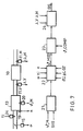
- the block diagram of Fig. 7 shows the catalyst 10, the front oxygen sensor 11.V, the rear Lambda probe 11.H, the injection assembly 18, the Throttle valve assembly 15, a speed sensor 19 and an engine temperature sensor 20.
- For the Controls are a start signal block 21, a temperature model block 22, a first comparator 23.1 and a second comparator 23.2 available.
- the start signal block 21 starts an assessment process if so is desired according to a start signal StS and thereby the motor temperature ⁇ _M below a threshold lies. It would be even more reliable to check the temperature of the To measure the catalyst and only then to start when its temperature is below a Threshold lies.
- FIGS. 7 and 8 it is assumed that the procedure only is started when the catalyst is approximately at ambient temperature lies.
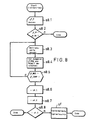
- step s8.1 ⁇ _M measured. If this temperature is above one Threshold temperature ⁇ _SW what in one step s8.2 is examined, the procedure is ended immediately, since it cannot be ruled out that the catalyst already above its conversion start temperature is heated. However, there is a cold start before, values of operating variables of the internal combustion engine and the catalyst measured (Step s8.3). With the help of the recorded values and one The model for the temperature of the catalyst is the Estimated catalyst temperature ⁇ _MOD determined (Step s8.4).
- step s8.5 it is examined (step s8.5) whether the estimated temperature is the above Comparative temperature ⁇ _COMP has reached. If this is not the case, steps s8.3 to s8.5 repeated. Otherwise, steps s8.6 to s8.8 executed completely following the steps s4.1 to s4.3 correspond with which it is examined whether the catalyst already converted. In step s8.8, that the catalyst hasn't converted yet, though the comparison temperature ⁇ _COMP has been exceeded, an error step sf is reached which corresponds to this designated step of FIG. 4 corresponds. After that or immediately after step s8.8, if namely the catalyst is converted properly reached the end of the process.
Landscapes
- Engineering & Computer Science (AREA)
- Chemical & Material Sciences (AREA)
- Chemical Kinetics & Catalysis (AREA)
- Combustion & Propulsion (AREA)
- Mechanical Engineering (AREA)
- General Engineering & Computer Science (AREA)
- Analytical Chemistry (AREA)
- Exhaust Gas After Treatment (AREA)
Description
Claims (4)
- Verfahren zum Beurteilen der Funktionsfähigkeit eines im Abgaskanal eines Verbrennungsmotors betriebenen Katalysators, bei demzur Untersuchung, bei welcher Temperatur der Katalysator zu konvertieren beginnt, eine Beurteilungsgröße BG berechnet wird, die dem Verhältnis der gemittelten Lambdawertschwankungen entspricht, wie sie von je einer hinter bzw. vor dem Katalysator angeordneten Abgassonde erfaßt werden und daß dann, wenn die Beurteilungsgröße BG einen Schwellwert unterschreitet, die zugehörige Temperatur des Katalysators als Konvertierungsbeginn-Temperatur erfaßt wird.der Verbrennungsmotor ausgehend von einem Zustand betrieben wird, bei dem die Katalysatortemperatur unter der Konvertierungsbeginn-Temperatur eines neuen Katalysators liegt,untersucht wird, bei welcher Temperatur der durch das Abgas des Motors erwärmte Katalysator zu konvertieren beginnt,die festgestellte Konvertierungsbeginn-Temperatur mit einer vorgegebenen Vergleichstemperatur verglichen wird, die über der Konvertierungsbeginn-Temperatur eines neuen Katalysators liegt und dann, wenn die festgestellte Konvertierungsbeginn-Temperatur unter der Vergleichstemperatur liegt, der Katalysator als funktionsfähig beurteilt wird, wobei
- Vorrichtung zum Beurteilen der Funktionsfähigkeit eines im Abgaskanal eines Verbrennungsmotors betriebenen Katalysators gemäß dem Verfahren nach Anspruch 1, mit einerund dann, wenn die festgestellte Konvertierungsbeginn-Temperatur unter der Vergleichstemperatur liegt, den Katalysator als funktionsfähig beurteilt, dadurch gekennzeichnet, daß die Ermittlungseinrichtung (13) zur Untersuchung, bei welcher Temperatur der Katalysator zu konvertieren beginnt, eine Beurteilungsgröße BG berechnet, die dem Verhältnis der gemittelten Lambdawertschwankungen entspricht, wie sie von je einer hinter bzw. vor dem Katalysator angeordneten Abgassonde erfaßt. werden und daß dann, wenn die Beurteilungsgröße BG einen Schwellwert unterschreitet, die zugehörige Temperatur des Katalysators als Konvertierungsbeginn-Temperatur erfaßt wird.Ermittlungseinrichtung (13) zum Untersuchen, bei welcher Temperatur der vom Abgas des Motors erwärmte Katalysator zu konvertieren beginnt, undeiner Vergleichs/Beurteilungseinrichtung (14.1), die die festgestellte Konvertierungsbeginn-Temperatur mit der Konvertierungsbeginn-Temperatur eines neuen Katalysators vergleicht,
- Verfahren zum Beurteilen der Funktionsfähigkeit eines im Abgaskanal eines Verbrennungsmotors betriebenen Katalysators, wobei
der Verbrennungsmotor ausgehend von einem Zustand betrieben wird, bei dem die Katalysatortemperatur unter der Konvertierungsbeginn-Temperatur eines neuen Katalysators liegt;
dadurch gekennzeichnet, daßder Verlauf der Temperatur des Katalysators aus einem Modell abgeschätzt wird, in das jeweils aktuelle Werte von Betriebsgrößen des Verbrennungsmotors eingegeben werden und wobei im Rahmen des Modells für die bei der Konvertierung freiwerdende Wärme von einem gerade noch brauchbaren Katalysator ausgegangen wird;die tatsächliche Temperatur des Katalysators untersucht wird, wenn die aus dem Modell abgeschätzte Temperatur eine Vergleichstemperatur erreicht hat, die über der Konvertierungsbeginn-Temperatur eines neuen Katalysators liegt; unddann, wenn die tatsächliche Temperatur des Katalysators über der Vergleichstemperatur liegt, der Katalysator als funktionsfähig beurteilt wird. - Vorrichtung zum Beurteilen der Funktionsfähigkeit eines im Abgaskanal eines Verbrennungsmotors betriebenen Katalysators gemäß dem Verfahren nach Anspruch 3, gekennzeichnet durch:eine Temperaturmodelleinrichtung (22) zum Abschätzen der Temperatur des durch das Abgas des Verbrennungsmotors erwärmten Katalysators aus einem Modell, in das jeweils aktuelle Werte von Betdebsgrößen des Verbrennungsmotors eingegeben werden und wobei im Rahmen des Modells für die bei der Konvertierung freiwerdende Wärme von einem gerade noch brauchbaren Katalysator ausgegangen wird.eine Vergleichseinrichtung (23), die ein Vergleichssignal ausgibt, wenn die aus dem Modell abgeschätzte Temperatur eine Vergleichstemperatur erreicht hat, die über der Konvertierungsbeginn-Temperatur eines neuen Katalysators liegt; undeine Beurteilungseinrichtung (24), die auf das Vergleichssignal hin die tatsächliche Temperatur des Katalysators untersucht und den Katalysator als funktionsfähig beurteilt, wenn die tatsächliche Temperatur über der Vergleichstemperatur liegt.
Applications Claiming Priority (3)
| Application Number | Priority Date | Filing Date | Title |
|---|---|---|---|
| DE4211092A DE4211092A1 (de) | 1992-04-03 | 1992-04-03 | Verfahren und Vorrichtung zum Beurteilen der Funktionsfähigkeit eines Katalysators |
| DE4211092 | 1992-04-03 | ||
| PCT/DE1993/000257 WO1993020340A2 (de) | 1992-04-03 | 1993-03-20 | Verfahren und vorrichtung zum beurteilen der funktionsfähigkeit eines katalysators |
Publications (3)
| Publication Number | Publication Date |
|---|---|
| EP0587836A1 EP0587836A1 (de) | 1994-03-23 |
| EP0587836B1 EP0587836B1 (de) | 1995-12-06 |
| EP0587836B2 true EP0587836B2 (de) | 1999-11-17 |
Family
ID=6455904
Family Applications (1)
| Application Number | Title | Priority Date | Filing Date |
|---|---|---|---|
| EP93905208A Expired - Lifetime EP0587836B2 (de) | 1992-04-03 | 1993-03-20 | Verfahren und vorrichtung zum beurteilen der funktionsfähigkeit eines katalysators |
Country Status (5)
| Country | Link |
|---|---|
| US (1) | US5675967A (de) |
| EP (1) | EP0587836B2 (de) |
| JP (1) | JPH06508414A (de) |
| DE (2) | DE4211092A1 (de) |
| WO (1) | WO1993020340A2 (de) |
Cited By (1)
| Publication number | Priority date | Publication date | Assignee | Title |
|---|---|---|---|---|
| DE102007045256A1 (de) * | 2007-09-21 | 2009-04-02 | Volkswagen Ag | Verfahren zum Prüfen der Funktionsfähigkeit eines Oxidationskatalysators einer Brennkraftmaschine |
Families Citing this family (71)
| Publication number | Priority date | Publication date | Assignee | Title |
|---|---|---|---|---|
| JP3331758B2 (ja) * | 1994-07-25 | 2002-10-07 | 株式会社デンソー | 排出ガス浄化装置の温度制御装置 |
| DE4330997A1 (de) * | 1993-09-13 | 1995-03-16 | Bosch Gmbh Robert | Verfahren zur Überwachung des Anspringverhaltens eines Katalysatorsystems in einem Kraftfahrzeug |
| US5419122A (en) * | 1993-10-04 | 1995-05-30 | Ford Motor Company | Detection of catalytic converter operability by light-off time determination |
| JP3244584B2 (ja) * | 1994-02-10 | 2002-01-07 | 株式会社日立製作所 | エンジン排気ガス浄化装置の診断方法及び装置 |
| DE4426020B4 (de) * | 1994-07-22 | 2005-07-28 | Robert Bosch Gmbh | Verfahren und Vorrichtung zur Überwachung der Funktionsfähigkeit eines Katalysators im Abgaskanal einer Brennkraftmaschine |
| JP3456058B2 (ja) * | 1995-02-10 | 2003-10-14 | 株式会社デンソー | 触媒の劣化検出装置及び排気浄化装置の異常検出装置 |
| US6523340B1 (en) * | 1995-02-10 | 2003-02-25 | Hitachi, Ltd. | Method and apparatus for diagnosing engine exhaust gas purification system |
| JP2753397B2 (ja) | 1995-03-16 | 1998-05-20 | ヒュンダイ モーター カンパニー | 触媒装置と酸素量検出装置の劣化判定装置およびその方法 |
| JP3239698B2 (ja) * | 1995-07-25 | 2001-12-17 | トヨタ自動車株式会社 | 内燃機関の触媒劣化判定装置 |
| DE19541903A1 (de) * | 1995-11-10 | 1997-05-15 | Bayerische Motoren Werke Ag | Überwachungssystem für die Abgasreinigung einer Brennkraftmaschine |
| JP3830568B2 (ja) * | 1995-12-18 | 2006-10-04 | 日本碍子株式会社 | 排気ガス浄化触媒の劣化検知方法 |
| DE19645202B4 (de) * | 1995-12-23 | 2006-05-11 | Volkswagen Ag | Verfahren zur Überwachung der Konvertierungsrate eines Abgaskatalysators für eine Brennkraftmaschine |
| JP3674017B2 (ja) | 1996-03-19 | 2005-07-20 | 株式会社デンソー | 排出ガス浄化用触媒劣化検出装置 |
| US5787705A (en) * | 1996-08-30 | 1998-08-04 | General Motors Corporation | Catalyst diagnostic |
| US5722236A (en) * | 1996-12-13 | 1998-03-03 | Ford Global Technologies, Inc. | Adaptive exhaust temperature estimation and control |
| JP3262157B2 (ja) * | 1997-01-24 | 2002-03-04 | 本田技研工業株式会社 | 内燃機関の燃料供給制御装置 |
| US5822979A (en) * | 1997-02-24 | 1998-10-20 | Ford Global Technologies, Inc. | Catalyst monitoring using a hydrocarbon sensor |
| DE19714293C1 (de) * | 1997-04-07 | 1998-09-03 | Siemens Ag | Verfahren zum Überprüfen der Konvertierungsfähigkeit eines Katalysators |
| DE19726791A1 (de) | 1997-06-24 | 1999-01-07 | Volkswagen Ag | Verfahren zur Überwachung der Konvertierungsrate eines Abgaskatalysators für eine Brennkraftmaschine |
| DE19736233C2 (de) | 1997-08-20 | 2001-03-29 | Siemens Ag | Verfahren zum Überprüfen eines Katalysators |
| US5996337A (en) * | 1998-02-06 | 1999-12-07 | Engelhard Corporation | Dynamic calorimetric sensor system |
| DE19811574A1 (de) * | 1998-03-17 | 1999-09-23 | Siemens Ag | Verfahren und Vorrichtung zum Überwachen der Funktionsfähigkeit eines Katalysators einer Brennkraftmaschine |
| US6202406B1 (en) * | 1998-03-30 | 2001-03-20 | Heralus Electro-Nite International N.V. | Method and apparatus for catalyst temperature control |
| US6050128A (en) * | 1998-05-28 | 2000-04-18 | Ford Global Technologies, Inc. | Catalyst deterioration monitoring |
| US6131439A (en) * | 1998-05-28 | 2000-10-17 | Ford Global Technologies, Inc. | Catalyst deterioration detection with sensor calibration |
| US6354076B1 (en) * | 1998-07-16 | 2002-03-12 | Honda Giken Kogyo Kabushiki Kaisha | Exhaust gas purification system of internal combustion engine |
| EP1106800B1 (de) * | 1998-07-17 | 2007-10-24 | Honda Giken Kogyo Kabushiki Kaisha | Verfahren zur beurteilung der verschlechterung eines katalysators zur abgasreinigung |
| DE19835748A1 (de) * | 1998-08-07 | 2000-02-10 | Daimler Chrysler Ag | Verfahren zur simulierten Bildung eines die momentane Katalysatortemperatur repräsentierenden Signals |
| US7886523B1 (en) | 1998-08-24 | 2011-02-15 | Legare Joseph E | Control methods for improved catalytic converter efficiency and diagnosis |
| US6651422B1 (en) | 1998-08-24 | 2003-11-25 | Legare Joseph E. | Catalyst efficiency detection and heating method using cyclic fuel control |
| US7707821B1 (en) | 1998-08-24 | 2010-05-04 | Legare Joseph E | Control methods for improved catalytic converter efficiency and diagnosis |
| DE19850338C2 (de) | 1998-11-02 | 2001-11-22 | Heraeus Electro Nite Int | Verfahren und Einrichtung zur Kontrolle und Beobachtung der Alterung eines Katalysators im Abgas von Verbrennungskraftmaschinen und des Schadstoffausstoßes |
| DE19907382A1 (de) * | 1999-02-20 | 2000-08-24 | Bayerische Motoren Werke Ag | Verfahren zur Abschätzung der Katalysatortemperatur |
| DE19933712A1 (de) * | 1999-07-19 | 2001-05-17 | Volkswagen Ag | Verfahren zur Regelung eines Arbeitsmodus einer Verbrennungskraftmaschine |
| DE60027987T8 (de) * | 1999-11-09 | 2007-02-15 | Honda Giken Kogyo K.K. | Steuerungssystem für eine Brennkraftmaschine |
| DE19955947C2 (de) | 1999-11-19 | 2002-04-11 | Heraeus Electro Nite Int | Verfahren zur Überprüfung der katalytischen Aktivität eines Katalysators |
| DE19955972C2 (de) * | 1999-11-19 | 2002-03-14 | Heraeus Electro Nite Int | Verfahren zum Kalibrieren eines Temperatursensors |
| DE19957185A1 (de) * | 1999-11-27 | 2001-05-31 | Volkswagen Ag | Verfahren und Vorrichtung zur Steuerung einer Aufheizphase zumindest eines in einem Abgaskanal einer Verbrennungskraftmaschine angeordneten Katalysators |
| JP4312325B2 (ja) * | 1999-12-28 | 2009-08-12 | 本田技研工業株式会社 | 排ガス浄化用触媒装置の劣化状態評価方法 |
| DE19963924A1 (de) * | 1999-12-31 | 2001-07-12 | Bosch Gmbh Robert | Verfahren zum Betreiben eines Speicherkatalysators einer Brennkraftmaschine |
| DE19963925A1 (de) * | 1999-12-31 | 2001-07-12 | Bosch Gmbh Robert | Verfahren zum Betreiben eines Speicherkatalysators einer Brennkraftmaschine |
| US6523341B1 (en) | 2000-01-07 | 2003-02-25 | Ford Global Technologies, Inc. | Cold start vehicle catalyst monitor |
| DE10013893A1 (de) * | 2000-03-21 | 2001-09-27 | Dmc2 Degussa Metals Catalysts | Verfahren zur Überprüfung der Funktionstüchtigkeit eines Abgasreinigungskatalysators |
| DE10031924A1 (de) | 2000-06-30 | 2002-01-10 | Bosch Gmbh Robert | Überprüfung von Katalysatorheizmassnahmen bei Brennkraftmaschinen |
| US6363713B1 (en) * | 2000-07-20 | 2002-04-02 | Ford Global Technologies, Inc. | On-board diagnostics for detecting the operation of diesel emissions control system |
| US6408616B1 (en) * | 2000-07-20 | 2002-06-25 | Ford Global Technologies, Inc. | Diesel OBD-II system for detection of degradation of catalyst activity |
| DE10038461B4 (de) * | 2000-08-07 | 2009-12-24 | Volkswagen Ag | Modell für einen NOx-Speicherkatalysator |
| DE10065123B4 (de) * | 2000-12-28 | 2012-12-20 | Robert Bosch Gmbh | Verfahren zur Steuerung einer Diagnose eines Katalysators im Abgas eines Verbrennungsmotors |
| US6668545B2 (en) * | 2001-03-30 | 2003-12-30 | General Motors Corporation | Catalyst warm-up assessment method for a motor vehicle catalytic converter |
| US7121085B2 (en) * | 2001-09-04 | 2006-10-17 | Ford Global Technologies, Llc | Method and apparatus for controlling hydrocarbon injection into engine exhaust to reduce NOx |
| DE10300555B4 (de) * | 2002-01-10 | 2009-03-19 | Toyota Jidosha Kabushiki Kaisha, Toyota-shi | Verschlechterungsermittelungsvorrichtung für eine Verbrennungsmotorabgassteuerungsvorrichtung und Verschlechterungsermittelungsverfahren |
| DE10248431A1 (de) * | 2002-10-17 | 2004-04-29 | Robert Bosch Gmbh | Verfahren zur Erkennung der Beladung eines Partikelfilters |
| DE10257172B4 (de) * | 2002-12-03 | 2011-06-22 | Volkswagen AG, 38440 | Verfahren zum Betreiben einer Verbrennungskraftmaschine mit einer flexiblen Anpassung der Bauteileschutzauslegung |
| DE10323247A1 (de) * | 2003-05-22 | 2004-12-09 | Umicore Ag & Co.Kg | Verfahren zum Betreiben eines Antriebssystems aus einem Dieselmotor mit einem Dieseloxidationskatalysator zur Abgasreinigung |
| DE102004004277A1 (de) * | 2004-01-27 | 2005-09-22 | Audi Ag | Verfahren zur Beurteilung der Güte eines einer Brennkraftmaschine eines Fahrzeuges, insbesondere eines Kraftfahrzeuges, nachgeschalteten Abgaskatalysators |
| DE102004006882B4 (de) * | 2004-02-12 | 2007-10-04 | Audi Ag | Verfahren zur Steuerung der Gemischanfettung einer magerlauffähigen Brennkraftmaschine eines Fahrzeugs, insbesondere eines Kraftfahrzeugs |
| DE102004058714B4 (de) * | 2004-12-06 | 2006-08-31 | Siemens Ag | Verfahren und Vorrichtung zum Überprüfen von Temperaturwerten eines Temperatursensors einer Brennkraftmaschine |
| US8544258B2 (en) * | 2005-09-23 | 2013-10-01 | GM Global Technology Operations LLC | Exhaust treatment system diagnostic via ammonium nitrite decomposition |
| US8112988B2 (en) * | 2006-03-16 | 2012-02-14 | Ford Global Technologies, Llc | System and method for desulfating a NOx trap |
| DE102008041385A1 (de) | 2008-08-20 | 2010-02-25 | Robert Bosch Gmbh | Verfahren und Vorrichtung zur Erkennung eines defekten Katalysators im Abgasstrom eines Verbrennungsmotors |
| JP5604852B2 (ja) * | 2009-11-06 | 2014-10-15 | トヨタ自動車株式会社 | 内燃機関の触媒装置温度推定装置 |
| US20120222399A1 (en) * | 2011-03-03 | 2012-09-06 | GM Global Technology Operations LLC | Oxidation catalyst burn threshold adjustment to avoid quenching |
| KR101305632B1 (ko) * | 2011-09-21 | 2013-09-09 | 기아자동차주식회사 | 배기정화장치의 피독감지시스템 및 감지방법 |
| DE102011115328A1 (de) | 2011-10-07 | 2013-04-11 | Mtu Friedrichshafen Gmbh | Verfahren zum Überwachen einer Abgasanlage |
| DE102011119214A1 (de) * | 2011-11-23 | 2013-05-23 | Daimler Ag | Verfahren zum Bestimmen einer Umsetzfähigkeit einer Abgasnachbehandlungseinrichtung für ein Fahrzeug |
| DE102012022840A1 (de) * | 2012-11-23 | 2014-05-28 | Audi Ag | Verfahren zur Überprüfung eines Abgaskatalysators |
| US20170234197A1 (en) * | 2016-02-12 | 2017-08-17 | GM Global Technology Operations LLC | Vehicle oxidation catalyst diagnostic strategy |
| KR101816426B1 (ko) * | 2016-08-01 | 2018-01-08 | 현대자동차주식회사 | 촉매 히팅 제어방법 |
| US11359529B2 (en) * | 2020-03-02 | 2022-06-14 | GM Global Technology Operations LLC | Monitoring of diesel oxidation catalyst in aftertreatment assembly |
| DE102020126961A1 (de) | 2020-10-14 | 2022-04-14 | Bayerische Motoren Werke Aktiengesellschaft | Verfahren zum Ermitteln eines Zustands eines Katalysators und Abgasnachbehandlungseinrichtung |
| DE102021114932A1 (de) | 2021-06-10 | 2022-12-15 | Bayerische Motoren Werke Aktiengesellschaft | Verfahren zum Betreiben einer Abgasnachbehandlungseinrichtung für eine Verbrennungskraftmaschine sowie Steuereinheit |
Citations (9)
| Publication number | Priority date | Publication date | Assignee | Title |
|---|---|---|---|---|
| DE2643739A1 (de) † | 1976-09-29 | 1978-03-30 | Bosch Gmbh Robert | Verfahren zur ueberwachung der aktivitaet von katalysatoren fuer die abgasreinigung |
| US4251990A (en) † | 1978-09-05 | 1981-02-24 | Nippondenso Co., Ltd. | Air-fuel ratio control system |
| US4622809A (en) † | 1984-04-12 | 1986-11-18 | Daimler-Benz Aktiengesellschaft | Method and apparatus for monitoring and adjusting λ-probe-controlled catalytic exhaust gas emission control systems of internal combustion engines |
| EP0231611A2 (de) † | 1986-01-27 | 1987-08-12 | General Motors Corporation | System zum Voraussagen der Temperatur eines katalytischen Umwandlers |
| US4831838A (en) † | 1985-07-31 | 1989-05-23 | Toyota Jidosha Kabushiki Kaisha | Double air-fuel ratio sensor system carrying out learning control operation |
| US4947818A (en) † | 1988-04-28 | 1990-08-14 | Toyota Jidosha Kabushiki Kaisha | Internal combustion engine with device for warning of malfunction in an air-fuel ratio control system |
| WO1991014856A1 (de) † | 1990-03-19 | 1991-10-03 | Emitec Gesellschaft Für Emissionstechnologie Mbh | Verfahren und vorrichtung zur steuerung eines verbrennungsmotors unter einbeziehung der aktuellen temperatur eines nachgeschalteten katalysators |
| US5060473A (en) † | 1988-07-13 | 1991-10-29 | Nissan Motor Company, Limited | System for detecting deterioration of catalyst in catalytic converter |
| EP0475177A2 (de) † | 1990-08-24 | 1992-03-18 | Nippondenso Co., Ltd. | Vorrichtung zum Feststellen des Reinigungsfaktors eines Katalysators in einem katalytischen Konverter für einen Innenverbrennungsmotor |
Family Cites Families (11)
| Publication number | Priority date | Publication date | Assignee | Title |
|---|---|---|---|---|
| JPS4828492U (de) * | 1971-08-09 | 1973-04-07 | ||
| DE2304622A1 (de) * | 1973-01-31 | 1974-08-15 | Bosch Gmbh Robert | Einrichtung zur ueberwachung von katalytischen reaktoren in abgasentgiftungsanlagen von brennkraftmaschinen |
| DE2444334A1 (de) * | 1974-09-17 | 1976-03-25 | Bosch Gmbh Robert | Verfahren und einrichtung zur ueberwachung der aktivitaet von katalytischen reaktoren |
| DE3500594C2 (de) * | 1985-01-10 | 1995-08-17 | Bosch Gmbh Robert | Zumeßsystem für eine Brennkraftmaschine zur Beeinflussung des Betriebsgemisches |
| DE3516981A1 (de) * | 1985-05-10 | 1986-11-13 | Audi AG, 8070 Ingolstadt | Verfahren zum ueberpruefen der funktionsfaehigkeit eines abgaskatalysators |
| IT1187855B (it) * | 1986-01-14 | 1987-12-23 | Fiat Auto Spa | Dispositivo di protezione per il catalizzatore di una marmitta catalitica per autoveicoli |
| JPH0315619A (ja) * | 1989-06-12 | 1991-01-24 | Nissan Motor Co Ltd | 内燃機関二次空気導入系の故障診断装置 |
| IT1237742B (it) * | 1989-12-22 | 1993-06-15 | Fiat Auto Spa | Dispositivo di allarme per la protezione di convertitori catalitici per i gas di scarico di motori endotermici e veicolo munito di tale dispositivo |
| GB9003316D0 (en) * | 1990-02-14 | 1990-04-11 | Lucas Ind Plc | Monitoring of operation of catalytic converter |
| DE4122787A1 (de) * | 1990-07-23 | 1992-01-30 | Volkswagen Ag | Einrichtung zur ueberwachung des konvertierungsgrads eines katalysators |
| JP3015619U (ja) | 1995-03-09 | 1995-09-05 | サングローブ株式会社 | 釣り用手袋 |
-
1992
- 1992-04-03 DE DE4211092A patent/DE4211092A1/de not_active Withdrawn
-
1993
- 1993-03-20 DE DE59301093T patent/DE59301093D1/de not_active Expired - Lifetime
- 1993-03-20 EP EP93905208A patent/EP0587836B2/de not_active Expired - Lifetime
- 1993-03-20 JP JP5516961A patent/JPH06508414A/ja active Pending
- 1993-03-20 WO PCT/DE1993/000257 patent/WO1993020340A2/de not_active Ceased
- 1993-03-20 US US08/157,089 patent/US5675967A/en not_active Expired - Lifetime
Patent Citations (9)
| Publication number | Priority date | Publication date | Assignee | Title |
|---|---|---|---|---|
| DE2643739A1 (de) † | 1976-09-29 | 1978-03-30 | Bosch Gmbh Robert | Verfahren zur ueberwachung der aktivitaet von katalysatoren fuer die abgasreinigung |
| US4251990A (en) † | 1978-09-05 | 1981-02-24 | Nippondenso Co., Ltd. | Air-fuel ratio control system |
| US4622809A (en) † | 1984-04-12 | 1986-11-18 | Daimler-Benz Aktiengesellschaft | Method and apparatus for monitoring and adjusting λ-probe-controlled catalytic exhaust gas emission control systems of internal combustion engines |
| US4831838A (en) † | 1985-07-31 | 1989-05-23 | Toyota Jidosha Kabushiki Kaisha | Double air-fuel ratio sensor system carrying out learning control operation |
| EP0231611A2 (de) † | 1986-01-27 | 1987-08-12 | General Motors Corporation | System zum Voraussagen der Temperatur eines katalytischen Umwandlers |
| US4947818A (en) † | 1988-04-28 | 1990-08-14 | Toyota Jidosha Kabushiki Kaisha | Internal combustion engine with device for warning of malfunction in an air-fuel ratio control system |
| US5060473A (en) † | 1988-07-13 | 1991-10-29 | Nissan Motor Company, Limited | System for detecting deterioration of catalyst in catalytic converter |
| WO1991014856A1 (de) † | 1990-03-19 | 1991-10-03 | Emitec Gesellschaft Für Emissionstechnologie Mbh | Verfahren und vorrichtung zur steuerung eines verbrennungsmotors unter einbeziehung der aktuellen temperatur eines nachgeschalteten katalysators |
| EP0475177A2 (de) † | 1990-08-24 | 1992-03-18 | Nippondenso Co., Ltd. | Vorrichtung zum Feststellen des Reinigungsfaktors eines Katalysators in einem katalytischen Konverter für einen Innenverbrennungsmotor |
Non-Patent Citations (2)
| Title |
|---|
| SAE Paper 910175 † |
| VDI Bericht 639 (1987) † |
Cited By (1)
| Publication number | Priority date | Publication date | Assignee | Title |
|---|---|---|---|---|
| DE102007045256A1 (de) * | 2007-09-21 | 2009-04-02 | Volkswagen Ag | Verfahren zum Prüfen der Funktionsfähigkeit eines Oxidationskatalysators einer Brennkraftmaschine |
Also Published As
| Publication number | Publication date |
|---|---|
| WO1993020340A3 (de) | 1994-01-06 |
| DE4211092A1 (de) | 1993-10-07 |
| EP0587836A1 (de) | 1994-03-23 |
| US5675967A (en) | 1997-10-14 |
| WO1993020340A2 (de) | 1993-10-14 |
| DE59301093D1 (de) | 1996-01-18 |
| EP0587836B1 (de) | 1995-12-06 |
| JPH06508414A (ja) | 1994-09-22 |
Similar Documents
| Publication | Publication Date | Title |
|---|---|---|
| EP0587836B1 (de) | Verfahren und vorrichtung zum beurteilen der funktionsfähigkeit eines katalysators | |
| DE10038655B4 (de) | Luftkraftstoffverhältnisregelgerät für Brennkraftmaschinen | |
| EP1336037B1 (de) | Verfahren und vorrichtung zur steuerung eines abgasnachbehandlungssystems | |
| DE19711295B4 (de) | Vorrichtung zur Ermittlung einer Verschlechterung eines Katalysators zur Abgasreinigung | |
| DE602005005849T2 (de) | Vorrichtung und verfahren zur bestimmung der von einem dieselmotor eines kraftfahrzeuges ausgestossenen nox-menge und diagnose- sowie motorverwaltungssystem mit einer derartigen vorrichtung | |
| DE19736233C2 (de) | Verfahren zum Überprüfen eines Katalysators | |
| EP0546318B1 (de) | Verfahren und Vorrichtung zur Ermittlung der Konvertierungsfähigkeit eines Katalysators | |
| DE102016222418A1 (de) | Verfahren zur Regelung einer Füllung eines Speichers eines Katalysators für eine Abgaskomponente | |
| DE19732167C2 (de) | Abgasreinigungsvorrichtung für Verbrennungsmotoren | |
| DE4100397C2 (de) | Verfahren und Anordnung zur Überwachung des Konvertierungsgrads eines Katalysators | |
| DE102018216980A1 (de) | Verfahren zur Regelung einer Füllung eines Speichers eines Katalysators für eine Abgaskomponente in Abhängigkeit von einer Alterung des Katalysators | |
| WO2018104425A1 (de) | Verfahren und steuergerät zur durchführung von diagnosen eines abgassystems eines verbrennungsmotors | |
| DE4302779A1 (de) | Verfahren zur Überprüfung der Funktionstüchtigkeit von Abgaskatalysatoren | |
| DE19843871A1 (de) | Diagnose eines NOx-Speicherkatalysators mit nachgeschaltetem NOx-Sensor | |
| DE102018251720A1 (de) | Verfahren zur Ermittlung einer maximalen Speicherfähigkeit eines Abgaskomponentenspeichers eines Katalysators | |
| DE102004031321C5 (de) | Verfahren zum Dosieren eines Brennstoffs in einen Abgaskanal einer Brennkraftmaschine und Vorrichtung zur Durchführung des Verfahrens | |
| EP1193376B1 (de) | Regelung eines NOx-Speicherkatalysators | |
| DE4435196C1 (de) | Verfahren zum Überprüfen eines Brennersystems zur Katalysatoraufheizung | |
| EP1329627B1 (de) | Verfahren und Vorrichtung zum Steuern einer Bauteilschutzfunktion | |
| DE69128398T2 (de) | Verfahren und Vorrichtung zur Überwachung der Verschlechterung des Abgasreinigers eines Innenverbrennungsmotors | |
| DE69705150T2 (de) | Verfahren zur Diagnose des Wirkungsgrades eines stromabwärts von einem Katalysator angeordneten Stochiometrischen Abgassensors | |
| DE3642402C2 (de) | ||
| DE102009054935B4 (de) | Verfahren und Vorrichtung zur Diagnose der Dynamik eines Abgassensors | |
| DE102005042843B4 (de) | Verfahren zur Diagnose einer in einem Abgasbereich einer Brennkraftmaschine angeordneten Abgasbehandlungsvorrichtung, und Vorrichtung zur Durchführung des Verfahrens | |
| DE10211345B4 (de) | Verfahren zum Bewerten des Aufwärmens eines Katalysators für einen katalytischen Konverter eines Kraftfahrzeugs |
Legal Events
| Date | Code | Title | Description |
|---|---|---|---|
| PUAI | Public reference made under article 153(3) epc to a published international application that has entered the european phase |
Free format text: ORIGINAL CODE: 0009012 |
|
| 17P | Request for examination filed |
Effective date: 19931105 |
|
| AK | Designated contracting states |
Kind code of ref document: A1 Designated state(s): DE FR SE |
|
| 17Q | First examination report despatched |
Effective date: 19941219 |
|
| GRAA | (expected) grant |
Free format text: ORIGINAL CODE: 0009210 |
|
| AK | Designated contracting states |
Kind code of ref document: B1 Designated state(s): DE FR SE |
|
| ET | Fr: translation filed | ||
| REF | Corresponds to: |
Ref document number: 59301093 Country of ref document: DE Date of ref document: 19960118 |
|
| PLBQ | Unpublished change to opponent data |
Free format text: ORIGINAL CODE: EPIDOS OPPO |
|
| PLBI | Opposition filed |
Free format text: ORIGINAL CODE: 0009260 |
|
| PLBI | Opposition filed |
Free format text: ORIGINAL CODE: 0009260 |
|
| 26 | Opposition filed |
Opponent name: ROTH-TECHNIK GMBH & CO. FORSCHUNG FUER AUTOMOBIL- Effective date: 19960808 |
|
| PLBF | Reply of patent proprietor to notice(s) of opposition |
Free format text: ORIGINAL CODE: EPIDOS OBSO |
|
| 26 | Opposition filed |
Opponent name: SIEMENS AKTIENGESELLSCHAFT ZENTRALABTEILUNG FORSCH Effective date: 19960906 Opponent name: ROTH-TECHNIK GMBH & CO. FORSCHUNG FUER AUTOMOBIL- Effective date: 19960808 |
|
| PLBF | Reply of patent proprietor to notice(s) of opposition |
Free format text: ORIGINAL CODE: EPIDOS OBSO |
|
| PLBF | Reply of patent proprietor to notice(s) of opposition |
Free format text: ORIGINAL CODE: EPIDOS OBSO |
|
| PLAW | Interlocutory decision in opposition |
Free format text: ORIGINAL CODE: EPIDOS IDOP |
|
| PLAW | Interlocutory decision in opposition |
Free format text: ORIGINAL CODE: EPIDOS IDOP |
|
| PUAH | Patent maintained in amended form |
Free format text: ORIGINAL CODE: 0009272 |
|
| STAA | Information on the status of an ep patent application or granted ep patent |
Free format text: STATUS: PATENT MAINTAINED AS AMENDED |
|
| 27A | Patent maintained in amended form |
Effective date: 19991117 |
|
| AK | Designated contracting states |
Kind code of ref document: B2 Designated state(s): DE FR SE |
|
| PLAW | Interlocutory decision in opposition |
Free format text: ORIGINAL CODE: EPIDOS IDOP |
|
| ET3 | Fr: translation filed ** decision concerning opposition | ||
| PGFP | Annual fee paid to national office [announced via postgrant information from national office to epo] |
Ref country code: FR Payment date: 20040318 Year of fee payment: 12 |
|
| PGFP | Annual fee paid to national office [announced via postgrant information from national office to epo] |
Ref country code: SE Payment date: 20040322 Year of fee payment: 12 |
|
| PG25 | Lapsed in a contracting state [announced via postgrant information from national office to epo] |
Ref country code: SE Free format text: LAPSE BECAUSE OF NON-PAYMENT OF DUE FEES Effective date: 20050321 |
|
| EUG | Se: european patent has lapsed | ||
| PG25 | Lapsed in a contracting state [announced via postgrant information from national office to epo] |
Ref country code: FR Free format text: LAPSE BECAUSE OF NON-PAYMENT OF DUE FEES Effective date: 20051130 |
|
| REG | Reference to a national code |
Ref country code: FR Ref legal event code: ST Effective date: 20051130 |
|
| PLAB | Opposition data, opponent's data or that of the opponent's representative modified |
Free format text: ORIGINAL CODE: 0009299OPPO |
|
| PGFP | Annual fee paid to national office [announced via postgrant information from national office to epo] |
Ref country code: DE Payment date: 20120502 Year of fee payment: 20 |
|
| REG | Reference to a national code |
Ref country code: DE Ref legal event code: R071 Ref document number: 59301093 Country of ref document: DE |
|
| PG25 | Lapsed in a contracting state [announced via postgrant information from national office to epo] |
Ref country code: DE Free format text: LAPSE BECAUSE OF EXPIRATION OF PROTECTION Effective date: 20130321 |