EP0587941A2 - Bearbeitungskopf für Werkzeugmaschinen mit Hypoidkegelradern zur Einstellung dieses Bearbeitungskopfes - Google Patents
Bearbeitungskopf für Werkzeugmaschinen mit Hypoidkegelradern zur Einstellung dieses Bearbeitungskopfes Download PDFInfo
- Publication number
- EP0587941A2 EP0587941A2 EP92118460A EP92118460A EP0587941A2 EP 0587941 A2 EP0587941 A2 EP 0587941A2 EP 92118460 A EP92118460 A EP 92118460A EP 92118460 A EP92118460 A EP 92118460A EP 0587941 A2 EP0587941 A2 EP 0587941A2
- Authority
- EP
- European Patent Office
- Prior art keywords
- fork
- fitted
- operating head
- axis
- support
- Prior art date
- Legal status (The legal status is an assumption and is not a legal conclusion. Google has not performed a legal analysis and makes no representation as to the accuracy of the status listed.)
- Withdrawn
Links
- 230000033001 locomotion Effects 0.000 title claims abstract description 11
- 239000003638 chemical reducing agent Substances 0.000 description 6
- 238000003754 machining Methods 0.000 description 3
- 230000008030 elimination Effects 0.000 description 2
- 238000003379 elimination reaction Methods 0.000 description 2
- 239000003570 air Substances 0.000 description 1
- 238000005452 bending Methods 0.000 description 1
- 239000002826 coolant Substances 0.000 description 1
- 239000000314 lubricant Substances 0.000 description 1
- 239000000463 material Substances 0.000 description 1
- 230000007246 mechanism Effects 0.000 description 1
- 238000000034 method Methods 0.000 description 1
- 238000003801 milling Methods 0.000 description 1
Images


Classifications
-
- B—PERFORMING OPERATIONS; TRANSPORTING
- B23—MACHINE TOOLS; METAL-WORKING NOT OTHERWISE PROVIDED FOR
- B23B—TURNING; BORING
- B23B31/00—Chucks; Expansion mandrels; Adaptations thereof for remote control
- B23B31/02—Chucks
- B23B31/34—Chucks with means enabling the workpiece to be reversed or tilted
-
- B—PERFORMING OPERATIONS; TRANSPORTING
- B23—MACHINE TOOLS; METAL-WORKING NOT OTHERWISE PROVIDED FOR
- B23Q—DETAILS, COMPONENTS, OR ACCESSORIES FOR MACHINE TOOLS, e.g. ARRANGEMENTS FOR COPYING OR CONTROLLING; MACHINE TOOLS IN GENERAL CHARACTERISED BY THE CONSTRUCTION OF PARTICULAR DETAILS OR COMPONENTS; COMBINATIONS OR ASSOCIATIONS OF METAL-WORKING MACHINES, NOT DIRECTED TO A PARTICULAR RESULT
- B23Q1/00—Members which are comprised in the general build-up of a form of machine, particularly relatively large fixed members
- B23Q1/25—Movable or adjustable work or tool supports
- B23Q1/44—Movable or adjustable work or tool supports using particular mechanisms
- B23Q1/50—Movable or adjustable work or tool supports using particular mechanisms with rotating pairs only, the rotating pairs being the first two elements of the mechanism
- B23Q1/54—Movable or adjustable work or tool supports using particular mechanisms with rotating pairs only, the rotating pairs being the first two elements of the mechanism two rotating pairs only
- B23Q1/5406—Movable or adjustable work or tool supports using particular mechanisms with rotating pairs only, the rotating pairs being the first two elements of the mechanism two rotating pairs only a single rotating pair followed perpendicularly by a single rotating pair
-
- B—PERFORMING OPERATIONS; TRANSPORTING
- B23—MACHINE TOOLS; METAL-WORKING NOT OTHERWISE PROVIDED FOR
- B23Q—DETAILS, COMPONENTS, OR ACCESSORIES FOR MACHINE TOOLS, e.g. ARRANGEMENTS FOR COPYING OR CONTROLLING; MACHINE TOOLS IN GENERAL CHARACTERISED BY THE CONSTRUCTION OF PARTICULAR DETAILS OR COMPONENTS; COMBINATIONS OR ASSOCIATIONS OF METAL-WORKING MACHINES, NOT DIRECTED TO A PARTICULAR RESULT
- B23Q5/00—Driving or feeding mechanisms; Control arrangements therefor
- B23Q5/02—Driving main working members
- B23Q5/04—Driving main working members rotary shafts, e.g. working-spindles
- B23Q5/043—Accessories for spindle drives
-
- Y—GENERAL TAGGING OF NEW TECHNOLOGICAL DEVELOPMENTS; GENERAL TAGGING OF CROSS-SECTIONAL TECHNOLOGIES SPANNING OVER SEVERAL SECTIONS OF THE IPC; TECHNICAL SUBJECTS COVERED BY FORMER USPC CROSS-REFERENCE ART COLLECTIONS [XRACs] AND DIGESTS
- Y10—TECHNICAL SUBJECTS COVERED BY FORMER USPC
- Y10T—TECHNICAL SUBJECTS COVERED BY FORMER US CLASSIFICATION
- Y10T409/00—Gear cutting, milling, or planing
- Y10T409/30—Milling
- Y10T409/306664—Milling including means to infeed rotary cutter toward work
- Y10T409/307672—Angularly adjustable cutter head
-
- Y—GENERAL TAGGING OF NEW TECHNOLOGICAL DEVELOPMENTS; GENERAL TAGGING OF CROSS-SECTIONAL TECHNOLOGIES SPANNING OVER SEVERAL SECTIONS OF THE IPC; TECHNICAL SUBJECTS COVERED BY FORMER USPC CROSS-REFERENCE ART COLLECTIONS [XRACs] AND DIGESTS
- Y10—TECHNICAL SUBJECTS COVERED BY FORMER USPC
- Y10T—TECHNICAL SUBJECTS COVERED BY FORMER US CLASSIFICATION
- Y10T409/00—Gear cutting, milling, or planing
- Y10T409/30—Milling
- Y10T409/30784—Milling including means to adustably position cutter
- Y10T409/307952—Linear adjustment
- Y10T409/308232—Linear adjustment and angular adjustment
-
- Y—GENERAL TAGGING OF NEW TECHNOLOGICAL DEVELOPMENTS; GENERAL TAGGING OF CROSS-SECTIONAL TECHNOLOGIES SPANNING OVER SEVERAL SECTIONS OF THE IPC; TECHNICAL SUBJECTS COVERED BY FORMER USPC CROSS-REFERENCE ART COLLECTIONS [XRACs] AND DIGESTS
- Y10—TECHNICAL SUBJECTS COVERED BY FORMER USPC
- Y10T—TECHNICAL SUBJECTS COVERED BY FORMER US CLASSIFICATION
- Y10T409/00—Gear cutting, milling, or planing
- Y10T409/30—Milling
- Y10T409/30784—Milling including means to adustably position cutter
- Y10T409/308512—Compound angular adjustment
Definitions
- This invention relates to an operating head for automatic machine tools which uses bevel gear pairs with hypoid crown wheel and pinion to transmit the chuck positioning motion.
- the invention relates to operating heads of the type comprising a fork fitted to a support with several degrees of freedom and a motor chuck, hinged to the said fork, which can be revolved and positioned along one or more axes in relation to the fork.
- the purpose of the invention is to obtain an operating head of the type indicated above which, though equipped with a high-power motor chuck (5-7 KW), is also very compact, so that work can be performed inside hollow objects if required, any play due to assembly tolerances and to wear of the parts can be eliminated, and sufficient rigidity is produced to enable the machine to withstand the stresses transmitted by the tool during machining without buckling.
- a high-power motor chuck 5-7 KW
- a further purpose of the invention is to obtain an operating head in which, again in order to improve the rigidity characteristics of the machine, the head "pivot point" projects less in relation to the chuck connection plane.
- Another purpose of the invention is to produce an operating head which is simpler to assemble than the ones currently used.
- US patent no. 4.904.131 describes an operating head which presents the general structure described above, in which the chuck positioning motion (axis A) is transmitted from a motor located in the fork support arm to the electric chuck via an inclined shaft with bevel gears at the ends which engage corresponding cogwheels, one built into the fork support arm and the other into the chuck support.
- This system produces a very compact head.
- German patent application 3.809.750 also describes an operating head in which the chuck positioning motion is transmitted via a set of bevel gears subject to an axial elastic force, in order to eliminate play due to wear.
- This system is quite complex and too bulky.
- Italian patent 1.220.733 illustrates a machine tool comprising an arm that moves along three cartesian axes; a fork fitted to the end of the arm can rotate around the arm axis and is equipped with a motor chuck presenting three degrees of freedom in relation to the fork.
- the present invention also falls into this category; it is designed to further improve this type of equipment by offering a head which simultaneously presents all the above-mentioned advantages of compactnesss, rigidity and elimination of play.
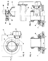
- no. 1 indicates the support arm of the operating head, the body of which, indicated as a whole as no. 2, basically consists of a fork with a motor chuck 5 fitted between fork arms 3 and 4.
- Fork 2 is fitted to arm or sleeve 1 via a hollow shaft 6, built into the fork, whose axis coincides with the axis of arm 1.
- Hollow shaft 6, together with the fork, can rotate around the axis of arm 1 (axis C), while the motor chuck can rotate around an axis passing through the fork arms which is orthogonal to the preceding one (axis A).
- Both these movements are numerically controlled in a known way, and serve to position and revolve the chuck and the tool with it.
- shaft 6 of fork 2 is fitted to arm 1 on bearings 7; a crown wheel with hypoid toothing 8, fixed to the said shaft, engages a corresponding bevel pinion 9, activated by a motor 10, which can be pushed axially by Belleville washers or the like to press against the crown wheel toothing in order to eliminate any play due to wear on the parts.
- Both motor 10 and the linkage constituted by crown wheel 8 and pinion 9 are housed inside arm 1.
- This configuration eliminates the need to use a reducer, (axis C) which is employed in known heads to attach the fork to the sleeve.
- This configuration means that the axis of reducer C must be aligned with the axis of sleeve 1, following which the fork is installed and then, after the fork has been fitted, the electric chuck axis is aligned with the sleeve and reducer axes.
- the axis of motor chuck 5 can be aligned with the fork axis during bench assembly and then, when the fork has been fitted to the sleeve, its axis is aligned with the sleeve axis by adjusting the locking screws used to attach hollow shaft 6 to the fork.
- reducer R means that the fork can be shortened, thus reducing the degree to which the pivot point projects in relation to the point at which the support arm is connected; so considerably improving the rigidity characteristics of the unit.
- chuck 5 is fitted to fork 2 via a pair of hubs or pins 11 and corresponding bearings 12.
- motor 10 (fig. 5) activates the rotations of the fork around the axis of arm 1 (axis C), while motor 15 (fig. 1) activates, via hypoid gear pair 14-13, the angular movements and/or swivel of the chuck around axis A-A passing through the fork arms, perpendicular to axis C.
- the bottom of crown wheel 13, fitted to the support hub of motor chuck 5, should preferably rest on a thrust bearing 16 located between the bottom of the crown wheel and wall 17 of the fork.
- the rotations of the chuck around axis A are detected by an encoder 18 or similar system, while air, lubricants, coolants, etc. are supplied to the motor chuck through a series of pipes (the piping system being shown as no. 19) passing though the chuck support hub in the other arm (4) of the fork.
- the fork can rotate around the axis of the support arm through an angle close to 360°, but the extent of its rotation is limited by the presence of one or more cams which activate limit and reset switches.
- this applies to machining performed on the outer surface of patterns, when it is useful for the tool, having machined all round the pattern until it reaches the starting point, to carry on for a little in order to ensure the continuity of the machined surface, without leaving grooves or the like at the point where machining started.
- the head in accordance with the invention is fitted with cams, which activate limit switches, not fitted directly to the fork shaft but located on a support connected to the shaft via a suitable reducer.
- a pulley 20 is fitted to fork shaft 5 coaxial with it; via a belt 21, pulley 20 drives a corresponding pulley 22 fitted idle on a shaft 30 built into the casing of arm 1.
- the ratio between pulleys 20 and 22 is such that the second pulley rotates at a lower speed than the first.
- the ratio between pulleys 20 and 22 might be 1:2.
- Cams 23, which activate limit and/or reset microswitches 24 built into the structure of fork support arm 1, are integral with pulley 22.
- motor 10 rotates the shaft of pinion 9 via a drive of known type.
- This shaft engages with crown wheel 8 built into fork shaft 6, which is thus made to rotate around axis C.
- Pinion 9 can be suitably loaded in such a way as to eliminate play due to wear on the parts.
- the extent of the fork rotations is detected by encoder 25 connected to the numerical control of the machine.
- the fork can rotate through more than 360° before the cams fitted to pulley 22 engage the limit switches.
- the fork can be made to rotate through over 400° around axis C.
- hypoid gear pair to transmit motion to the fork means that fewer gears are required, thus enabling the projection of the pivot point to be reduced and space to be saved and, without any change in the overall size of the operating head, providing more room for tools, which can therefore be selected from a wider range.
- the chuck is positioned around axis A by hypoid gear pair 14-13 activated by motor 15 (fig. 1).
- motor 15 fig. 1
- the use of a large crown wheel produces greater resistance to the stresses transmitted by the tool, as the arm of the lever (distance between axis A and toothing of crown wheel 13) which transmits these stresses to the remaining mechanisms is larger.
Landscapes
- Engineering & Computer Science (AREA)
- Mechanical Engineering (AREA)
- Automatic Tool Replacement In Machine Tools (AREA)
Applications Claiming Priority (2)
| Application Number | Priority Date | Filing Date | Title |
|---|---|---|---|
| ITPC920011A IT1261026B (it) | 1992-07-22 | 1992-07-22 | Testa operatrice per macchine utensili automatiche, in cui si utilizzano coppie coniche ipoidali per trasmettere il moto per il posizionamento del mandrino |
| ITPC920011 | 1992-07-22 |
Publications (2)
| Publication Number | Publication Date |
|---|---|
| EP0587941A2 true EP0587941A2 (de) | 1994-03-23 |
| EP0587941A3 EP0587941A3 (en) | 1994-06-08 |
Family
ID=11389001
Family Applications (1)
| Application Number | Title | Priority Date | Filing Date |
|---|---|---|---|
| EP19920118460 Withdrawn EP0587941A3 (en) | 1992-07-22 | 1992-10-29 | Operating head for automatic machine tools in which hypoid bevel gear pairs are used to transmit the chuck positioning motion |
Country Status (3)
| Country | Link |
|---|---|
| US (1) | US5257883A (de) |
| EP (1) | EP0587941A3 (de) |
| IT (1) | IT1261026B (de) |
Cited By (4)
| Publication number | Priority date | Publication date | Assignee | Title |
|---|---|---|---|---|
| WO2000061315A1 (en) * | 1999-04-07 | 2000-10-19 | Amada Company, Limited | Automatic bending system and manipulator for the system |
| EP2014409A1 (de) * | 2007-10-24 | 2009-01-14 | WENZEL Präzision GmbH | Mehrachsen-Drehkopf mit integrierter Steuereinrichtung und Koordinatenmessmaschine mit solch einem Mehrachsen-Drehkopf |
| CN100464086C (zh) * | 2007-01-24 | 2009-02-25 | 大连光洋科技工程有限公司 | 一种快换方法以及所用快换结构 |
| CN100563919C (zh) * | 2007-03-06 | 2009-12-02 | 乔福机械股份有限公司 | 直驱式主轴头组件及其制造方法与综合加工机 |
Families Citing this family (13)
| Publication number | Priority date | Publication date | Assignee | Title |
|---|---|---|---|---|
| US5584621A (en) * | 1995-06-13 | 1996-12-17 | Bertsche Engineering Corp. | Direct drive multiple axes rotary spindle head for milling machine |
| ES2171121B1 (es) | 2000-07-06 | 2004-02-16 | Soraluce S Coop | Sistema de modularidad y accionamiento aplicable al carnero-cabezal de una fresadora. |
| DE102005007371A1 (de) * | 2005-02-17 | 2006-08-24 | Siemens Ag | Elektrische Maschine |
| CZ302304B6 (cs) * | 2005-05-31 | 2011-02-16 | Trimill, A. S. | Polohovací a brzdicí zarízení výkyvného vretena |
| JP4996393B2 (ja) * | 2006-09-14 | 2012-08-08 | 津田駒工業株式会社 | 工作機械用の加工用ヘッド |
| US7293340B1 (en) | 2006-12-15 | 2007-11-13 | Roundtop Machinery Industries Co., Ltd | Direct drive spindle, machining center and methods of fabricating the same |
| CN100475437C (zh) * | 2007-01-15 | 2009-04-08 | 大连光洋科技工程有限公司 | 由交流永磁同步外转子式力矩电机驱动的双摆铣头 |
| DE102008016497A1 (de) | 2008-03-31 | 2009-10-01 | Liebherr-Verzahntechnik Gmbh | Bearbeitungskopf |
| JP5496323B2 (ja) * | 2010-04-23 | 2014-05-21 | 株式会社牧野フライス製作所 | 主軸ユニット及びテーブルユニット、並びに工作機械 |
| TWI417155B (zh) | 2010-07-20 | 2013-12-01 | Ind Tech Res Inst | 齒輪減速式旋轉主軸頭 |
| TWI417165B (zh) | 2010-07-20 | 2013-12-01 | Ind Tech Res Inst | 工作機械之旋轉主軸頭 |
| CN102962682B (zh) * | 2012-11-26 | 2014-12-17 | 桂林电子科技大学 | 精密齿轮传动式a/c轴双摆角数控铣头 |
| EP2767356B1 (de) * | 2013-02-19 | 2017-11-22 | SMW-AUTOBLOK Spannsysteme GmbH | Schwenk-Spannfutter |
Family Cites Families (12)
| Publication number | Priority date | Publication date | Assignee | Title |
|---|---|---|---|---|
| FR2102405A5 (de) * | 1970-07-16 | 1972-04-07 | Gambin Sa | |
| US3719254A (en) * | 1971-11-10 | 1973-03-06 | Dotco Inc | Lubricated angle drive attachment for air operated tool |
| SU673387A1 (ru) * | 1978-01-13 | 1979-07-15 | Предприятие П/Я В-8852 | Шпиндельна головка |
| DE2944983C2 (de) * | 1979-11-07 | 1982-07-22 | Maho Werkzeugmaschinenbau Babel & Co, 8962 Pfronten | Spindelstock für eine Universal-Fräs- und Bohrmaschine |
| US4370080A (en) * | 1980-10-01 | 1983-01-25 | The Ingersoll Milling Machine Company | Tool head having nutating spindle |
| DE3311289A1 (de) * | 1983-03-28 | 1984-10-04 | Th. Kekeisen GmbH & Co Maschinen- und Werkzeugfabrik, 7958 Laupheim | Universalfraeskopf fuer eine werkzeugmaschine |
| DE8336030U1 (de) * | 1983-12-15 | 1985-05-23 | Werkzeugmaschinenfabrik Adolf Waldrich Coburg Gmbh & Co, 8630 Coburg | Vorrichtung zum verschwenken einer werkzeugaufnahmevorrichtung, insbesondere eines winkelfraeskopfes, am freien (unteren) ende eines fraesspindelschlittens |
| US4683772A (en) * | 1985-07-25 | 1987-08-04 | Westinghouse Electric Corp. | Hand gear train with three degrees of freedom |
| GB2215243B (en) * | 1988-02-24 | 1992-02-26 | Jobs Spa | A chuck head for automatic machine tools. |
| JPH01222809A (ja) * | 1988-02-26 | 1989-09-06 | Shin Nippon Koki Kk | 工作機械 |
| IT1220733B (it) * | 1988-03-09 | 1990-06-21 | Jobs Spa | Testa operatrice per macchine utensili automatiche atta ad aumentare il numero degli assi di lavoro della macchina |
| US4990039A (en) * | 1989-11-17 | 1991-02-05 | Liaw Y T | Structure of vertical milling machine ram adapter |
-
1992
- 1992-07-22 IT ITPC920011A patent/IT1261026B/it active IP Right Grant
- 1992-10-29 EP EP19920118460 patent/EP0587941A3/en not_active Withdrawn
- 1992-11-16 US US07/977,236 patent/US5257883A/en not_active Expired - Fee Related
Cited By (5)
| Publication number | Priority date | Publication date | Assignee | Title |
|---|---|---|---|---|
| WO2000061315A1 (en) * | 1999-04-07 | 2000-10-19 | Amada Company, Limited | Automatic bending system and manipulator for the system |
| US6722178B1 (en) | 1999-04-07 | 2004-04-20 | Amada Company, Limited | Automatic bending system and manipulator for the system |
| CN100464086C (zh) * | 2007-01-24 | 2009-02-25 | 大连光洋科技工程有限公司 | 一种快换方法以及所用快换结构 |
| CN100563919C (zh) * | 2007-03-06 | 2009-12-02 | 乔福机械股份有限公司 | 直驱式主轴头组件及其制造方法与综合加工机 |
| EP2014409A1 (de) * | 2007-10-24 | 2009-01-14 | WENZEL Präzision GmbH | Mehrachsen-Drehkopf mit integrierter Steuereinrichtung und Koordinatenmessmaschine mit solch einem Mehrachsen-Drehkopf |
Also Published As
| Publication number | Publication date |
|---|---|
| IT1261026B (it) | 1996-04-29 |
| EP0587941A3 (en) | 1994-06-08 |
| ITPC920011A0 (it) | 1992-07-22 |
| ITPC920011A1 (it) | 1994-01-22 |
| US5257883A (en) | 1993-11-02 |
Similar Documents
| Publication | Publication Date | Title |
|---|---|---|
| US5257883A (en) | Operating head for automatic machine tools | |
| US4502830A (en) | Industrial robot | |
| KR850000058B1 (ko) | 산업로보트 | |
| USRE33732E (en) | Method of machining a workpiece in a turret lathe and an NC lathe for performing this method | |
| US5533418A (en) | Spherical robotic shoulder joint | |
| US5111709A (en) | Industrial robot with a telescopic horizontal arm | |
| US4047448A (en) | Robot head | |
| US4785513A (en) | Turret having rotating and non-rotating tooling | |
| US5882158A (en) | Drive assembly | |
| US5996329A (en) | Multi-axis machining head | |
| US5413439A (en) | Universal spindle head for machine tool | |
| JP2722345B2 (ja) | 産業用ロボットの手首用2自由度駆動機構 | |
| US5056971A (en) | Operating head chuck unit for automatic machine tools | |
| US6003409A (en) | Play-free device for driving a rotary table | |
| AU645950B2 (en) | Spindle drive | |
| USRE34155E (en) | Machining a workpiece in a turret lathe and an NC lathe therefor | |
| JPH0726673B2 (ja) | 運動機構 | |
| CN113579314B (zh) | 一种八轴立式加工中心 | |
| JP3418452B2 (ja) | 複合運動駆動装置 | |
| US4528876A (en) | Universal single spindle pin crankshaft lathe | |
| JP4272759B2 (ja) | 加工ヘッド装置 | |
| JPH0763906B2 (ja) | 位置決め装置 | |
| EP0174916B1 (de) | Industrieroboteranordnung | |
| JPH02292189A (ja) | 球面作業ロボット | |
| JP3907301B2 (ja) | タレット刃物台装置 |
Legal Events
| Date | Code | Title | Description |
|---|---|---|---|
| PUAI | Public reference made under article 153(3) epc to a published international application that has entered the european phase |
Free format text: ORIGINAL CODE: 0009012 |
|
| AK | Designated contracting states |
Kind code of ref document: A2 Designated state(s): DE ES FR GB IT |
|
| PUAL | Search report despatched |
Free format text: ORIGINAL CODE: 0009013 |
|
| AK | Designated contracting states |
Kind code of ref document: A3 Designated state(s): DE ES FR GB IT |
|
| 17P | Request for examination filed |
Effective date: 19941125 |
|
| 17Q | First examination report despatched |
Effective date: 19951228 |
|
| GRAG | Despatch of communication of intention to grant |
Free format text: ORIGINAL CODE: EPIDOS AGRA |
|
| GRAH | Despatch of communication of intention to grant a patent |
Free format text: ORIGINAL CODE: EPIDOS IGRA |
|
| STAA | Information on the status of an ep patent application or granted ep patent |
Free format text: STATUS: THE APPLICATION IS DEEMED TO BE WITHDRAWN |
|
| 18D | Application deemed to be withdrawn |
Effective date: 19961202 |