EP0588281A1 - Hygienische Einrichtung für Badezimmer - Google Patents
Hygienische Einrichtung für Badezimmer Download PDFInfo
- Publication number
- EP0588281A1 EP0588281A1 EP19930114664 EP93114664A EP0588281A1 EP 0588281 A1 EP0588281 A1 EP 0588281A1 EP 19930114664 EP19930114664 EP 19930114664 EP 93114664 A EP93114664 A EP 93114664A EP 0588281 A1 EP0588281 A1 EP 0588281A1
- Authority
- EP
- European Patent Office
- Prior art keywords
- human body
- light receiving
- hygienic apparatus
- receiving means
- remote controller
- Prior art date
- Legal status (The legal status is an assumption and is not a legal conclusion. Google has not performed a legal analysis and makes no representation as to the accuracy of the status listed.)
- Granted
Links
Images
Classifications
-
- E—FIXED CONSTRUCTIONS
- E03—WATER SUPPLY; SEWERAGE
- E03D—WATER-CLOSETS OR URINALS WITH FLUSHING DEVICES; FLUSHING VALVES THEREFOR
- E03D5/00—Special constructions of flushing devices, e.g. closed flushing system
- E03D5/10—Special constructions of flushing devices, e.g. closed flushing system operated electrically, e.g. by a photo-cell; also combined with devices for opening or closing shutters in the bowl outlet and/or with devices for raising/or lowering seat and cover and/or for swiveling the bowl
- E03D5/105—Special constructions of flushing devices, e.g. closed flushing system operated electrically, e.g. by a photo-cell; also combined with devices for opening or closing shutters in the bowl outlet and/or with devices for raising/or lowering seat and cover and/or for swiveling the bowl touchless, e.g. using sensors
-
- E—FIXED CONSTRUCTIONS
- E03—WATER SUPPLY; SEWERAGE
- E03D—WATER-CLOSETS OR URINALS WITH FLUSHING DEVICES; FLUSHING VALVES THEREFOR
- E03D9/00—Sanitary or other accessories for lavatories ; Devices for cleaning or disinfecting the toilet room or the toilet bowl; Devices for eliminating smells
- E03D9/08—Devices in the bowl producing upwardly-directed sprays; Modifications of the bowl for use with such devices ; Bidets; Combinations of bowls with urinals or bidets; Hot-air or other devices mounted in or on the bowl, urinal or bidet for cleaning or disinfecting
Definitions
- the present invention relates to a hygienic apparatus for a bathroom or a sanitary room, and it particularly relates to such a hygienic apparatus provided with human body detecting means.
- the human body detecting means is disposed at an end of a casing, and it is comprised of light emitting means adapted to emit an optical signal toward a human body, and light receiving means adapted to receive the optical signal reflected from the human body, thereby detecting where the human body is.
- remote controller light receiving means is disposed in the casing, and it is positioned adjacent to the position where the human body detecting means is disposed.
- the remote controller light receiving means is adapted to receive other optical signals emitted by a remote controller disposed on a wall of a bathroom, thereby actuating the "CW-630" hygienic apparatus.
- the human body detecting means and the remote controller light receiving means are disposed at different positions independently. Consequently, it is needed to provide the casing with two windows at the end, windows which are adapted to pass the optical signal reflected from the human body and the other optical signals emitted by the remote controller, respectively.
- Such a construction adversely affects the operability in the assembling operation, and it eventually results in an increasing manufacturing cost.
- a hygienic apparatus for a bathroom can carry out the aforementioned object, and it comprises: human body detecting means including light emitting means adapted to emit an optical signal toward a human body, and first light receiving means adapted to receive the optical signal reflected from the human body, thereby detecting where a human body is; second light receiving means adapted to receive other optical signals emitted by a remote controller disposed on a wall of a bathroom; and a body including a window, the window adapted to incorporate the human body detecting means and the second light receiving means therein.
- the human body detecting means and the second light receiving means are disposed in the single window formed in the body.
- the window is shared by the human body detecting means and the second light receiving means.
- the single window can be shared by the human body detecting means and the second light receiving means, and accordingly it can be adapted to pass the optical signal reflected from the human body as well as the other optical signals emitted by the remote controller disposed independently of the present hygienic apparatus in a bathroom.
- the assembly operation of the present hygienic apparatus can be simplified as a whole, and thereby the manufacturing cost can be reduced.
- the body of the present hygienic apparatus can further include a casing which is disposed on the top rear side thereof, which is adapted to hold a lid and a seat rotatably, and which has the window.
- the second light receiving means can be preferably disposed between the light emitting means and the first light receiving means of the human body detecting means.
- the human body detecting means can be preferably adapted to detect whether the human body is in front of the body or not.
- the human body detecting means can be preferably adapted to detect whether the human body is on the body or not.
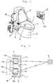
- Figure 1 illustrates the present hygienic apparatus in a perspective view
- Figure 2 illustrates human body detecting means and second light receiving means of the present hygienic apparatus in a cross-sectional view.
- the present hygienic apparatus 1 comprises a body or a toilet bowl 2 provided with a casing 3. Further, the casing 3 is disposed on the top rear side of the toilet bowl 2, and it is adapted to rotatably hold a seat 4 and a lid 5 at their ends. Furthermore, in the rear inner wall of the toilet bowl 2, there is held a nozzle 6 movably back and forth.
- the nozzle 6 is adapted to spout lukewarm water having an adequate temperature in a sufficient amount upward in Figure 1, thereby carrying out the anus washing or the female pubic portion washing. Further, the nozzle 6 is adapted to blow lukewarm air having an adequate temperature in a sufficient amount upward in Figure 1, thereby drying the human private parts after the respective washing operations.
- a remote controller 8 on a bathroom wall.
- the remote controller 8 is provided with switches (not shown) disposed therein, and it is further provided with remote controller light emitting means 8a on the bottom in the drawing.
- the remote controller light emitting means 8a emits an optical signal or beam, e.g., an infrared radiation in general, which is allotted to one of the switches.
- the human body detecting means 7 can be a human body detecting sensor which is adapted to detect whether the human body is in front of the toilet bowl 2 or not, or it can be a seated state detecting sensor which is adapted to detect whether the human body is on the seat 3 of the toilet bowl 2 or not.
- the human body detecting means 7 includes a container 13.
- a substrate 10 is disposed in the container 13, and light emitting means 11 and light receiving means 12 are disposed on the top side and the bottom side of the substrate 10, respectively, in the drawing.
- the light emitting means 11 and the light receiving means 12 constitute the human body detecting means 7, and they can include a photoelectric transducer, which converts light into electricity, or vice versa, such as a photodiode, a phototransistor, a light emitting diode, or the like.
- the light emitting means 11 can include a light emitting diode
- the light receiving means 12 can include a photodiode.
- the light emitting means 11 includes a tubular body 11a, a light emitting device 11b, and a light emitting lens 11c.
- the tubular body 11a is fixed above the top side of the substrate 10 in Figure 2, and it has an opening at the right end in the drawing.
- the light emitting device 11b is disposed so as to penetrate through the bottom of the tubular body 11a at the left end in the drawing, and it is fixed on the top side of the substrate 10 in the drawing.
- the light emitting lens 11c is disposed adjacent to the opening of the tubular body 11a so as to close the opening of the tubular body 11a.
- the light receiving means 12 includes a tubular body 12a, a light receiving device 12b, and a light receiving lens 12c.
- the tubular body 12a is fixed above the bottom side of the substrate 10 in Figure 2, and it has an opening at the right end in the drawing.
- the light receiving device 12b is disposed so as to penetrate through the bottom of the tubular body 12a at the left end in the drawing, and it is fixed on the bottom side of the substrate 10 in the drawing.
- the light receiving lens 12c is disposed adjacent to the opening of the tubular body 12a so as to close the opening of the tubular body 12a.
- the light emitting device 11b of the light emitting means 11 emits an optical signal or beam toward a human body 9 by way of the light emitting lens 11c.
- the optical signal is reflected from the human body 9.
- the reflected optical signal is received by the light receiving device 12b by way of the light receiving lens 12c, thereby detecting where the human body 9 is.
- the human body detecting means 7 carries out the detection of the human body 9 by the triangulation.
- remote controller light receiving means 14 is disposed fixedly on the intermediate side of the substrate 10 so as to interpose between the light emitting means 11 and the light receiving means 12 of the human body detecting means 7. It is adapted to receive the optical signals, other than the optical signal emitted by the light emitting means 11, emitted by the remote controller light emitting means 8a of the remote controller 8 illustrated in Figure 1.
- the remote controller light receiving means 14 can include a photoelectric transducer, which converts light into electricity, or vice versa, such as a photodiode, a phototransistor, or the like.
- the remote controller light receiving means 14 is disposed between the light emitting means 11 and the light receiving means 12 in order to effectively utilize the dead space between the light emitting means and the light receiving means of the conventional hygienic apparatus.
- the operation of the present hygienic apparatus 1 will be hereinafter described.
- an anus washing optical signal is emitted by the remote controller light emitting means 8a toward the remote controller light receiving means 14 which is incorporated into the human body detecting means 7.
- controlling means (not shown, but disposed in the casing 3) instructs the nozzle 6 to carry out the anus washing in accordance with the optical signal received by way of the remote controller light receiving means 14.
- the nozzle 6 advances forward, and it washes the anus of the user.
- the present hygienic apparatus 1 not only the light emitting means 11 and the light receiving means 12 of the human body detecting means 7 but also the remote controller light receiving means 14 are disposed in the single window "W" which is formed in the casing 3. To put it differently, in the present hygienic apparatus 1, the window "W" is shared by the human body detecting means 7 and the remote controller light receiving means 14. With the construction, the assembly operation of the present hygienic apparatus 1 can be simplified as a whole, and thereby the manufacturing cost can be reduced. In addition, the present hygienic apparatus 1 can be improved in the appearance as well.
- the conventional human body detecting means of the conventional hygienic apparatuses is provided with the dead space between the light emitting means and the light receiving means because it is similarly adapted to detect where the human body is by the triangulation.
- the remote controller light receiving means 14 is disposed between the light emitting means 11 and the light receiving means 12 of the human body detecting means 7 to eliminate the dead space, the detection of the human body 9 can be carried out accurately without interference because the light emitting means 11 is adapted to emit the optical signal having high directivity and the light receiving means 12 is adapted to receive the reflected optical signal with high sensitivity. Consequently, the present hygienic apparatus 1 can utilize the dead space effectively.
- the present hygienic apparatus 1 it is unnecessary to provide the casing 3 with a space for the remote controller light receiving means 14 independently of the human body detecting means 7. All in all, the present hygienic apparatus 1 is down-sized, thereby resulting in a further manufacturing cost reduction.
- a hygienic apparatus for a bathroom which is comprised of human body detecting device including light emitting device adapted to emit an optical signal toward a human body, and first light receiving device adapted to receive the optical signal reflected from the human body, thereby detecting where a human body is, second light receiving device adapted to receive other optical signals emitted by a remote controller disposed on a wall of a bathroom, and a body including a window, the window adapted to incorporate the human body detecting device and the second light receiving device therein.
- the window is shared by the human body detecting device and the second light receiving device.
Landscapes
- Health & Medical Sciences (AREA)
- Public Health (AREA)
- Engineering & Computer Science (AREA)
- Life Sciences & Earth Sciences (AREA)
- Hydrology & Water Resources (AREA)
- Water Supply & Treatment (AREA)
- Aviation & Aerospace Engineering (AREA)
- Molecular Biology (AREA)
- Epidemiology (AREA)
- Sanitary Device For Flush Toilet (AREA)
- Geophysics And Detection Of Objects (AREA)
- Bidet-Like Cleaning Device And Other Flush Toilet Accessories (AREA)
Applications Claiming Priority (2)
| Application Number | Priority Date | Filing Date | Title |
|---|---|---|---|
| JP245243/92 | 1992-09-14 | ||
| JP24524392A JPH0693646A (ja) | 1992-09-14 | 1992-09-14 | トイレ用衛生装置 |
Publications (2)
| Publication Number | Publication Date |
|---|---|
| EP0588281A1 true EP0588281A1 (de) | 1994-03-23 |
| EP0588281B1 EP0588281B1 (de) | 1997-01-02 |
Family
ID=17130791
Family Applications (1)
| Application Number | Title | Priority Date | Filing Date |
|---|---|---|---|
| EP19930114664 Expired - Lifetime EP0588281B1 (de) | 1992-09-14 | 1993-09-13 | Hygienische Einrichtung für Badezimmer |
Country Status (4)
| Country | Link |
|---|---|
| EP (1) | EP0588281B1 (de) |
| JP (1) | JPH0693646A (de) |
| DE (1) | DE69307064T2 (de) |
| ES (1) | ES2100409T3 (de) |
Cited By (2)
| Publication number | Priority date | Publication date | Assignee | Title |
|---|---|---|---|---|
| CN102041841A (zh) * | 2010-12-08 | 2011-05-04 | 广东朝阳卫浴有限公司 | 一种节水型智能冲水箱系统 |
| CN104024544A (zh) * | 2011-12-28 | 2014-09-03 | 豪威株式会社 | 基于力传感器的输入设备和具有这种输入设备的坐浴盆 |
Families Citing this family (2)
| Publication number | Priority date | Publication date | Assignee | Title |
|---|---|---|---|---|
| DE102013101209B4 (de) * | 2012-12-19 | 2019-08-14 | Hamberger Industriewerke Gmbh | WC-Sitzgarnitur |
| JP7342546B2 (ja) * | 2019-09-11 | 2023-09-12 | 株式会社アイシン | 便座装置 |
Citations (2)
| Publication number | Priority date | Publication date | Assignee | Title |
|---|---|---|---|---|
| US4805247A (en) * | 1987-04-08 | 1989-02-21 | Coyne & Delany Co. | Apparatus for preventing unwanted operation of sensor activated flush valves |
| EP0487977A1 (de) * | 1990-11-29 | 1992-06-03 | Inax Corporation | Automatische Wasserspüleinrichtung für W.C.-Anlage |
Family Cites Families (2)
| Publication number | Priority date | Publication date | Assignee | Title |
|---|---|---|---|---|
| JPH0614275B2 (ja) * | 1983-12-07 | 1994-02-23 | 松下電器産業株式会社 | 料理メニュー生成装置 |
| JP2982813B2 (ja) * | 1988-08-30 | 1999-11-29 | 小糸工業株式会社 | ワイヤレスリモコン操作式着座センサ付衛生処理装置 |
-
1992
- 1992-09-14 JP JP24524392A patent/JPH0693646A/ja active Pending
-
1993
- 1993-09-13 EP EP19930114664 patent/EP0588281B1/de not_active Expired - Lifetime
- 1993-09-13 ES ES93114664T patent/ES2100409T3/es not_active Expired - Lifetime
- 1993-09-13 DE DE1993607064 patent/DE69307064T2/de not_active Expired - Lifetime
Patent Citations (2)
| Publication number | Priority date | Publication date | Assignee | Title |
|---|---|---|---|---|
| US4805247A (en) * | 1987-04-08 | 1989-02-21 | Coyne & Delany Co. | Apparatus for preventing unwanted operation of sensor activated flush valves |
| EP0487977A1 (de) * | 1990-11-29 | 1992-06-03 | Inax Corporation | Automatische Wasserspüleinrichtung für W.C.-Anlage |
Cited By (3)
| Publication number | Priority date | Publication date | Assignee | Title |
|---|---|---|---|---|
| CN102041841A (zh) * | 2010-12-08 | 2011-05-04 | 广东朝阳卫浴有限公司 | 一种节水型智能冲水箱系统 |
| CN104024544A (zh) * | 2011-12-28 | 2014-09-03 | 豪威株式会社 | 基于力传感器的输入设备和具有这种输入设备的坐浴盆 |
| CN104024544B (zh) * | 2011-12-28 | 2016-12-28 | 豪威株式会社 | 基于力传感器的输入设备和具有这种输入设备的坐浴盆 |
Also Published As
| Publication number | Publication date |
|---|---|
| DE69307064T2 (de) | 1997-05-15 |
| JPH0693646A (ja) | 1994-04-05 |
| DE69307064D1 (de) | 1997-02-13 |
| ES2100409T3 (es) | 1997-06-16 |
| EP0588281B1 (de) | 1997-01-02 |
Similar Documents
| Publication | Publication Date | Title |
|---|---|---|
| JP2585087Y2 (ja) | 自動洗浄装置 | |
| EP0487977B1 (de) | Automatische Wasserspüleinrichtung für W.C.-Anlage | |
| CN112942517B (zh) | 一种智能马桶的冲厕控制方法和系统 | |
| SK282320B6 (sk) | Elektronické bezdotykové ovládacie zariadenie a spôsob bezdotykového ovládania zariadenia | |
| CN102373739A (zh) | 坐便器自动排水阀及工作方法 | |
| JP2005168719A (ja) | トイレ装置 | |
| EP0588281B1 (de) | Hygienische Einrichtung für Badezimmer | |
| JP2001299644A (ja) | トイレ装置 | |
| KR101974383B1 (ko) | 마이크로파센서를 사용한 소변감지장치 | |
| GB2264557A (en) | Water supply apparatus | |
| CN209924062U (zh) | 一种红外感应装置及自动冲水便器 | |
| JPH0659437B2 (ja) | 芳香剤等の自動噴霧装置 | |
| JP2982813B2 (ja) | ワイヤレスリモコン操作式着座センサ付衛生処理装置 | |
| CN118415627B (zh) | 一种人体目标姿态检测方法及智能产品的控制方法 | |
| JP3158424B2 (ja) | 厨房装置 | |
| JP2005273284A (ja) | 衛生洗浄装置 | |
| JP2022063473A (ja) | トイレ装置用リモコン | |
| CN216892693U (zh) | 一种马桶的脚部感应装置和马桶 | |
| JP2000303535A (ja) | 使用状態検出機能付き大便器 | |
| JPH01244034A (ja) | 便器洗浄装置 | |
| CN222908972U (zh) | 背景抑制卫浴感应器和感应自启动设备 | |
| JP2797627B2 (ja) | 厨房装置 | |
| JP2025184434A (ja) | トイレ装置 | |
| JPH0614275U (ja) | 局部洗浄装置付便器 | |
| KR200320587Y1 (ko) | 비데의 자동물내림구조 |
Legal Events
| Date | Code | Title | Description |
|---|---|---|---|
| PUAI | Public reference made under article 153(3) epc to a published international application that has entered the european phase |
Free format text: ORIGINAL CODE: 0009012 |
|
| 17P | Request for examination filed |
Effective date: 19930913 |
|
| AK | Designated contracting states |
Kind code of ref document: A1 Designated state(s): DE ES GB |
|
| RIN1 | Information on inventor provided before grant (corrected) |
Inventor name: TAKAMATA, AKIRA Inventor name: MIZUTANI, MASATAKA Inventor name: IDOTA, IKUYA Inventor name: KAWAI, SHINJI Inventor name: YAMAGUCHI, YUJI Inventor name: ISHIDA, AKIRA Inventor name: TANAKA, SEIJI |
|
| 17Q | First examination report despatched |
Effective date: 19940426 |
|
| GRAG | Despatch of communication of intention to grant |
Free format text: ORIGINAL CODE: EPIDOS AGRA |
|
| GRAH | Despatch of communication of intention to grant a patent |
Free format text: ORIGINAL CODE: EPIDOS IGRA |
|
| GRAH | Despatch of communication of intention to grant a patent |
Free format text: ORIGINAL CODE: EPIDOS IGRA |
|
| GRAA | (expected) grant |
Free format text: ORIGINAL CODE: 0009210 |
|
| AK | Designated contracting states |
Kind code of ref document: B1 Designated state(s): DE ES GB |
|
| REF | Corresponds to: |
Ref document number: 69307064 Country of ref document: DE Date of ref document: 19970213 |
|
| REG | Reference to a national code |
Ref country code: ES Ref legal event code: FG2A Ref document number: 2100409 Country of ref document: ES Kind code of ref document: T3 |
|
| PLBE | No opposition filed within time limit |
Free format text: ORIGINAL CODE: 0009261 |
|
| 26N | No opposition filed | ||
| REG | Reference to a national code |
Ref country code: GB Ref legal event code: IF02 |
|
| REG | Reference to a national code |
Ref country code: ES Ref legal event code: PC2A |
|
| REG | Reference to a national code |
Ref country code: GB Ref legal event code: 732E |
|
| PGFP | Annual fee paid to national office [announced via postgrant information from national office to epo] |
Ref country code: ES Payment date: 20090929 Year of fee payment: 17 |
|
| PGFP | Annual fee paid to national office [announced via postgrant information from national office to epo] |
Ref country code: GB Payment date: 20090909 Year of fee payment: 17 |
|
| PGFP | Annual fee paid to national office [announced via postgrant information from national office to epo] |
Ref country code: DE Payment date: 20090910 Year of fee payment: 17 |
|
| GBPC | Gb: european patent ceased through non-payment of renewal fee |
Effective date: 20100913 |
|
| REG | Reference to a national code |
Ref country code: DE Ref legal event code: R119 Ref document number: 69307064 Country of ref document: DE Effective date: 20110401 |
|
| PG25 | Lapsed in a contracting state [announced via postgrant information from national office to epo] |
Ref country code: DE Free format text: LAPSE BECAUSE OF NON-PAYMENT OF DUE FEES Effective date: 20110401 |
|
| PG25 | Lapsed in a contracting state [announced via postgrant information from national office to epo] |
Ref country code: GB Free format text: LAPSE BECAUSE OF NON-PAYMENT OF DUE FEES Effective date: 20100913 |
|
| REG | Reference to a national code |
Ref country code: ES Ref legal event code: FD2A Effective date: 20111019 |
|
| PG25 | Lapsed in a contracting state [announced via postgrant information from national office to epo] |
Ref country code: ES Free format text: LAPSE BECAUSE OF NON-PAYMENT OF DUE FEES Effective date: 20100914 |