EP0588377B1 - Méthode et appareil pour le transfert aseptique de fluide - Google Patents
Méthode et appareil pour le transfert aseptique de fluide Download PDFInfo
- Publication number
- EP0588377B1 EP0588377B1 EP93118056A EP93118056A EP0588377B1 EP 0588377 B1 EP0588377 B1 EP 0588377B1 EP 93118056 A EP93118056 A EP 93118056A EP 93118056 A EP93118056 A EP 93118056A EP 0588377 B1 EP0588377 B1 EP 0588377B1
- Authority
- EP
- European Patent Office
- Prior art keywords
- needle
- needles
- tank
- tube
- fluid
- Prior art date
- Legal status (The legal status is an assumption and is not a legal conclusion. Google has not performed a legal analysis and makes no representation as to the accuracy of the status listed.)
- Expired - Lifetime
Links
- 239000012530 fluid Substances 0.000 title claims abstract description 85
- 238000012546 transfer Methods 0.000 title claims abstract description 72
- 238000000034 method Methods 0.000 title claims abstract description 42
- 239000000463 material Substances 0.000 claims abstract description 101
- 230000035515 penetration Effects 0.000 claims description 60
- 229920001971 elastomer Polymers 0.000 claims description 25
- 230000000694 effects Effects 0.000 claims description 11
- 238000004891 communication Methods 0.000 claims description 10
- 230000001954 sterilising effect Effects 0.000 claims description 7
- 230000007480 spreading Effects 0.000 claims description 4
- 238000003892 spreading Methods 0.000 claims description 4
- 230000008569 process Effects 0.000 description 17
- 239000010408 film Substances 0.000 description 16
- 238000012545 processing Methods 0.000 description 16
- 241000894006 Bacteria Species 0.000 description 11
- 230000000712 assembly Effects 0.000 description 10
- 238000000429 assembly Methods 0.000 description 10
- 238000011109 contamination Methods 0.000 description 9
- 210000002445 nipple Anatomy 0.000 description 9
- 125000006850 spacer group Chemical group 0.000 description 9
- 238000013459 approach Methods 0.000 description 7
- 235000013365 dairy product Nutrition 0.000 description 7
- 239000001963 growth medium Substances 0.000 description 7
- 230000000903 blocking effect Effects 0.000 description 6
- 238000009434 installation Methods 0.000 description 6
- 230000006835 compression Effects 0.000 description 5
- 238000007906 compression Methods 0.000 description 5
- 239000000356 contaminant Substances 0.000 description 5
- 239000013039 cover film Substances 0.000 description 5
- 230000006870 function Effects 0.000 description 5
- 239000011159 matrix material Substances 0.000 description 5
- 238000012986 modification Methods 0.000 description 5
- 230000004048 modification Effects 0.000 description 5
- 229920002943 EPDM rubber Polymers 0.000 description 3
- 230000008901 benefit Effects 0.000 description 3
- 238000005520 cutting process Methods 0.000 description 3
- 230000001066 destructive effect Effects 0.000 description 3
- 239000000806 elastomer Substances 0.000 description 3
- 238000003780 insertion Methods 0.000 description 3
- 230000037431 insertion Effects 0.000 description 3
- 230000001788 irregular Effects 0.000 description 3
- 238000012423 maintenance Methods 0.000 description 3
- 238000004519 manufacturing process Methods 0.000 description 3
- 208000035143 Bacterial infection Diseases 0.000 description 2
- RRHGJUQNOFWUDK-UHFFFAOYSA-N Isoprene Chemical compound CC(=C)C=C RRHGJUQNOFWUDK-UHFFFAOYSA-N 0.000 description 2
- 229920000690 Tyvek Polymers 0.000 description 2
- 239000004775 Tyvek Substances 0.000 description 2
- 239000000853 adhesive Substances 0.000 description 2
- 230000001070 adhesive effect Effects 0.000 description 2
- 230000004075 alteration Effects 0.000 description 2
- 208000022362 bacterial infectious disease Diseases 0.000 description 2
- 239000011248 coating agent Substances 0.000 description 2
- 238000000576 coating method Methods 0.000 description 2
- 239000000645 desinfectant Substances 0.000 description 2
- 239000013536 elastomeric material Substances 0.000 description 2
- 230000013011 mating Effects 0.000 description 2
- VNWKTOKETHGBQD-UHFFFAOYSA-N methane Chemical compound C VNWKTOKETHGBQD-UHFFFAOYSA-N 0.000 description 2
- 239000000203 mixture Substances 0.000 description 2
- -1 mother cultures Substances 0.000 description 2
- 230000002829 reductive effect Effects 0.000 description 2
- 238000005070 sampling Methods 0.000 description 2
- 238000012163 sequencing technique Methods 0.000 description 2
- 239000007858 starting material Substances 0.000 description 2
- 238000005728 strengthening Methods 0.000 description 2
- 230000000007 visual effect Effects 0.000 description 2
- VXNZUUAINFGPBY-UHFFFAOYSA-N 1-Butene Chemical compound CCC=C VXNZUUAINFGPBY-UHFFFAOYSA-N 0.000 description 1
- LFQSCWFLJHTTHZ-UHFFFAOYSA-N Ethanol Chemical compound CCO LFQSCWFLJHTTHZ-UHFFFAOYSA-N 0.000 description 1
- VGGSQFUCUMXWEO-UHFFFAOYSA-N Ethene Chemical compound C=C VGGSQFUCUMXWEO-UHFFFAOYSA-N 0.000 description 1
- 239000005977 Ethylene Substances 0.000 description 1
- IAYPIBMASNFSPL-UHFFFAOYSA-N Ethylene oxide Chemical compound C1CO1 IAYPIBMASNFSPL-UHFFFAOYSA-N 0.000 description 1
- 239000004677 Nylon Substances 0.000 description 1
- 239000004743 Polypropylene Substances 0.000 description 1
- 229920006266 Vinyl film Polymers 0.000 description 1
- 208000027418 Wounds and injury Diseases 0.000 description 1
- 230000004308 accommodation Effects 0.000 description 1
- 230000001154 acute effect Effects 0.000 description 1
- 239000000654 additive Substances 0.000 description 1
- 230000003466 anti-cipated effect Effects 0.000 description 1
- 230000001580 bacterial effect Effects 0.000 description 1
- 230000004888 barrier function Effects 0.000 description 1
- 238000005452 bending Methods 0.000 description 1
- IAQRGUVFOMOMEM-UHFFFAOYSA-N butene Natural products CC=CC IAQRGUVFOMOMEM-UHFFFAOYSA-N 0.000 description 1
- 238000005660 chlorination reaction Methods 0.000 description 1
- 238000004140 cleaning Methods 0.000 description 1
- 238000013329 compounding Methods 0.000 description 1
- 150000001875 compounds Chemical class 0.000 description 1
- 239000012141 concentrate Substances 0.000 description 1
- 230000006378 damage Effects 0.000 description 1
- 230000007423 decrease Effects 0.000 description 1
- 229920006351 engineering plastic Polymers 0.000 description 1
- 230000007613 environmental effect Effects 0.000 description 1
- 238000011049 filling Methods 0.000 description 1
- 238000011010 flushing procedure Methods 0.000 description 1
- 235000013305 food Nutrition 0.000 description 1
- 210000003918 fraction a Anatomy 0.000 description 1
- 239000012634 fragment Substances 0.000 description 1
- 230000008570 general process Effects 0.000 description 1
- 229920001903 high density polyethylene Polymers 0.000 description 1
- 239000004700 high-density polyethylene Substances 0.000 description 1
- 208000015181 infectious disease Diseases 0.000 description 1
- 230000036512 infertility Effects 0.000 description 1
- 208000014674 injury Diseases 0.000 description 1
- 238000005304 joining Methods 0.000 description 1
- 230000000670 limiting effect Effects 0.000 description 1
- 238000011068 loading method Methods 0.000 description 1
- 239000002184 metal Substances 0.000 description 1
- 238000002156 mixing Methods 0.000 description 1
- 238000010068 moulding (rubber) Methods 0.000 description 1
- 239000003345 natural gas Substances 0.000 description 1
- 229920001778 nylon Polymers 0.000 description 1
- 238000004806 packaging method and process Methods 0.000 description 1
- 230000036961 partial effect Effects 0.000 description 1
- 239000002245 particle Substances 0.000 description 1
- 239000004033 plastic Substances 0.000 description 1
- 229920003023 plastic Polymers 0.000 description 1
- 229920000642 polymer Polymers 0.000 description 1
- 229920000098 polyolefin Polymers 0.000 description 1
- 229920001155 polypropylene Polymers 0.000 description 1
- 230000000644 propagated effect Effects 0.000 description 1
- 230000008707 rearrangement Effects 0.000 description 1
- 230000009467 reduction Effects 0.000 description 1
- 230000004044 response Effects 0.000 description 1
- 230000000284 resting effect Effects 0.000 description 1
- 230000000717 retained effect Effects 0.000 description 1
- 230000002441 reversible effect Effects 0.000 description 1
- 238000011012 sanitization Methods 0.000 description 1
- 238000007789 sealing Methods 0.000 description 1
- 230000035945 sensitivity Effects 0.000 description 1
- 238000001228 spectrum Methods 0.000 description 1
- 230000000087 stabilizing effect Effects 0.000 description 1
- 238000004659 sterilization and disinfection Methods 0.000 description 1
- 229920001897 terpolymer Polymers 0.000 description 1
- 238000012549 training Methods 0.000 description 1
- 241001515965 unidentified phage Species 0.000 description 1
- 125000000391 vinyl group Chemical group [H]C([*])=C([H])[H] 0.000 description 1
- 229920002554 vinyl polymer Polymers 0.000 description 1
Images







Classifications
-
- B—PERFORMING OPERATIONS; TRANSPORTING
- B67—OPENING, CLOSING OR CLEANING BOTTLES, JARS OR SIMILAR CONTAINERS; LIQUID HANDLING
- B67D—DISPENSING, DELIVERING OR TRANSFERRING LIQUIDS, NOT OTHERWISE PROVIDED FOR
- B67D7/00—Apparatus or devices for transferring liquids from bulk storage containers or reservoirs into vehicles or into portable containers, e.g. for retail sale purposes
- B67D7/02—Apparatus or devices for transferring liquids from bulk storage containers or reservoirs into vehicles or into portable containers, e.g. for retail sale purposes for transferring liquids other than fuel or lubricants
-
- B—PERFORMING OPERATIONS; TRANSPORTING
- B67—OPENING, CLOSING OR CLEANING BOTTLES, JARS OR SIMILAR CONTAINERS; LIQUID HANDLING
- B67B—APPLYING CLOSURE MEMBERS TO BOTTLES JARS, OR SIMILAR CONTAINERS; OPENING CLOSED CONTAINERS
- B67B7/00—Hand- or power-operated devices for opening closed containers
- B67B7/24—Hole-piercing devices
- B67B7/26—Hole-piercing devices combined with spouts
-
- C—CHEMISTRY; METALLURGY
- C12—BIOCHEMISTRY; BEER; SPIRITS; WINE; VINEGAR; MICROBIOLOGY; ENZYMOLOGY; MUTATION OR GENETIC ENGINEERING
- C12M—APPARATUS FOR ENZYMOLOGY OR MICROBIOLOGY; APPARATUS FOR CULTURING MICROORGANISMS FOR PRODUCING BIOMASS, FOR GROWING CELLS OR FOR OBTAINING FERMENTATION OR METABOLIC PRODUCTS, i.e. BIOREACTORS OR FERMENTERS
- C12M33/00—Means for introduction, transport, positioning, extraction, harvesting, peeling or sampling of biological material in or from the apparatus
- C12M33/04—Means for introduction, transport, positioning, extraction, harvesting, peeling or sampling of biological material in or from the apparatus by injection or suction, e.g. using pipettes, syringes, needles
- C12M33/06—Means for introduction, transport, positioning, extraction, harvesting, peeling or sampling of biological material in or from the apparatus by injection or suction, e.g. using pipettes, syringes, needles for multiple inoculation or multiple collection of samples
-
- Y—GENERAL TAGGING OF NEW TECHNOLOGICAL DEVELOPMENTS; GENERAL TAGGING OF CROSS-SECTIONAL TECHNOLOGIES SPANNING OVER SEVERAL SECTIONS OF THE IPC; TECHNICAL SUBJECTS COVERED BY FORMER USPC CROSS-REFERENCE ART COLLECTIONS [XRACs] AND DIGESTS
- Y10—TECHNICAL SUBJECTS COVERED BY FORMER USPC
- Y10S—TECHNICAL SUBJECTS COVERED BY FORMER USPC CROSS-REFERENCE ART COLLECTIONS [XRACs] AND DIGESTS
- Y10S604/00—Surgery
- Y10S604/905—Aseptic connectors or couplings, e.g. frangible, piercable
Definitions
- a fluid transfer device comprising
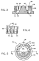
- the seal member 26 is seen generally in FIGURES 5 and 6.
- Seal member 26 has generally opposing first and second surfaces 58 and 60 respectively.
- the first surface 58 has a first generally outwardly projecting central portion 62 which is shown convex, and an upstanding outer wall portion 64 generally corresponding to outer wall 36 of adapter 24.
- Penetration zone 66 is between wall portion 64 and central portion 62.
- Penetration zone 66 is generally coextensive with the circumference of the first surface at its lower terminus between upstanding wall portion 64 and central portion 62.
- the adapter, the seal member, and the channel member are jointly configured and adapted to assure the alignment of channels 86 with holes 40, with an intervening pierceable, self-closing portion of the seal member corresponding to penetration zone 66.
- This alignment assures an unimpeded passage of needles through the fitting 93 along paths prescribed for the needles.
- the central axis of the fluid receiver assembly extends through channel member 28, seal member 26, and adapter 24, and thus corresponds with central axis 90 of channel member 28, as shown in FIGURES 8 and 11.
- FIGURE 26 shows a top view of the adapter 224 used in receiver assembly 212.
- the component parts of adapter 224 correspond to the related parts on adapter 24, with appropriate modifications to accommodate the four concentric rows of needle paths.
- adapter 224 has an outer wall 236, a central core member 238, and a plurality of holes 240 between the outer wall 236 and central core member 238.
- Continuous channel 246 between outer wall 236 and core member 238 includes bridging rings 274 between secondary channels 246A, 246B, 246C, and 246D, which incorporate the four concentric rings of holes 240.
- Bridging walls 252 separate the holes radially as in adapter 24 of FIGURES 2-4. Bridging rings 274 separate the concentric rows.
- the control means 222 can, for example, be a conventional pneumatic controller, with lines 225 being pneumatic lines suitable for carrying pneumatic energy to pneumatic cylinders in drivers 221.
- control means 222 could be a conventional electrical switching means, with wires 225 running to electrical power sources at driving means 221.
- the actual power and control means, in this particular illustrated embodiment of the method of effecting the transfer, are not critical, so long as both needle bundles 295A and 295B are driven at the same time, or essentially the same time, or in close enough sequencing to avoid contamination of either tank by drawing in of outside air, or spillage of fluid contents.
- the invention provides a novel means for aseptically transferring a fluid from a first enclosure to a second enclosure, including use of novel transfer and receiver apparatus, the environment in at least one of the enclosures being susceptible to contamination from the outside environment.
- the invention further provides a fitting, and an associated receiver assembly for facilitating making communicative fluid flow connection between the enclosures.
- the invention also provides a needle holder and a needle bundle useful in effecting the connection and the transfer.
- a transfer assembly comprising two needle bundles and a connecting flexible tubing accommodates the transfer where both tanks are stationary and not easily transported.
- the invention further provides novel methods for transferring material aseptically into an environment which is susceptible to contamination from the outside environment, or for aseptic transfers between enclosures.
Landscapes
- Engineering & Computer Science (AREA)
- Life Sciences & Earth Sciences (AREA)
- Health & Medical Sciences (AREA)
- Wood Science & Technology (AREA)
- Mechanical Engineering (AREA)
- Bioinformatics & Cheminformatics (AREA)
- Organic Chemistry (AREA)
- Chemical & Material Sciences (AREA)
- Zoology (AREA)
- Microbiology (AREA)
- Genetics & Genomics (AREA)
- Molecular Biology (AREA)
- Biotechnology (AREA)
- Biochemistry (AREA)
- General Engineering & Computer Science (AREA)
- General Health & Medical Sciences (AREA)
- Sustainable Development (AREA)
- Biomedical Technology (AREA)
- Infusion, Injection, And Reservoir Apparatuses (AREA)
- Physical Or Chemical Processes And Apparatus (AREA)
- Feeding, Discharge, Calcimining, Fusing, And Gas-Generation Devices (AREA)
- Medical Preparation Storing Or Oral Administration Devices (AREA)
- Coating Apparatus (AREA)
Claims (16)
- Dispositif de transfert d'un fluide comprenant :a) a faisceau d'aiguilles (95) comportant (i) a porte-aiguilles (96) présentant une pluralité de canaux de maintien d'aiguilles (100) s'étendant entre des première et seconde extrémités (97,98), (ii) une pluralité d'aiguilles (101) dans le porte-aiguilles, ces aiguilles ayant des premières parties extrêmes d'aiguille (102) s'étendant à partir de la première extrémité (97) du porte-aiguilles et des passes (164) à travers les aiguilles, etb) un tube (266) relié à la seconde extrémité (98) du porte-aiguilles (96) et s'étendant à partir d'elle afin de transporter un fluide.
- Dispositif de transfert d'un fluide suivant la revendication 1 caractérisé en ce qu'il comporte un capuchon (112) imperméable aux bactéries et recouvrant les portions des aiguilles qui s'étendent à partir de la première extrémité du porte-aiguilles.
- Dispositif de transfert d'un fluide suivant l'une quelconque des revendications 1 ou 2 caractérisé en ce que les premières parties extrêmes (102) des aiguilles (101) sont décalées de telle façon que ces parties extrêmes des aiguilles s'étendent sur des distances différentes à partir de la première extrémité (97) du porte-aiguilles (96).
- Dispositif de transfert d'un fluide suivant l'une quelconque des revendications 1 à 3 caractérisé en ce que le tube (266) est adapté de manière à pouvoir transporter au moins autant de fluide que la somme des capacités de transport des passages (164) dans les aiguilles.
- Dispositif de transfert d'un fluide suivant l'une quelconque des revendications 1 à 4 caractérisé en ce qu'il comporte un repère (152) sur le faisceau d'aiguilles pour orienter en coopération ce faisceau d'aiguilles par rapport à un récepteur (12) capable de recevoir le porte-aiguilles.
- Dispositif de transfert d'un fluide suivant l'une quelconque des revendications 1 à 5 caractérisé en ce que le tube (266) a des première et seconde extrémités, le porte-aiguilles est monté sur une première extrémité du tube et il comprend a premier connecteur (295A) de pénétration dans un récipient et le tube comporte un second connecteur (295B) de pénétration dans un récipient prévu sur la seconde extrémité du tube, le tube étant adapté de manière à transporter un fluide transmis à travers les premier et second connecteurs de pénétration dans un récipient.
- Dispositif de transfert d'un fluide suivant la revendication 6 caractérisé en ce que le second connecteur (295B) de pénétration dans un récipient comprend un second porte-aiguilles ayant des première et seconde extrémités et comprenant (i) au moins a canal (100) de maintien d'une aiguille s'étendant entre les première et seconde extrémités (97,98), (ii) au moins une aiguille (101) dans le porte-aiguilles, cette aiguille ayant une première partie extrême d'aiguille (102) s'étendant à partir de la première extrémité du porte-aiguilles et a passe (164) à travers l'aiguille si bien que l'aiguille établit un passée de communication pour un fluide entre le tube et l'environnement extérieur à ce tube.
- Dispositif de transfert d'un fluide suivant l'une quelconque des revendications 6 ou 7 caractérisé en ce qu'il connue deux récipients (10) pour établir une communication entre eux pour le passe d'un fluide.
- Dispositif de transfert d'un fluide suivant l'une quelconque des revendications 1 à 8 caractérisé en ce que le second connecteur (295B) de pénétration dans un récipient comprend un second faisceau d'aiguilles (95), ce second faisceau d'aiguilles comprenant (i) a second porte-aiguilles (96) ayant une pluralité de canaux de maintien d'aiguilles qui s'étendent entre ses première et seconde extrémités, (ii) une seconde pluralité d'aiguilles (101) dans le second porte-aiguilles, cette seconde pluralité d'aiguilles ayant des parties extrêmes d'aiguille (102) s'étendant à partir de la première extrémité du seconde porte-aiguilles, et des passes (164) à travers la seconde pluralité d'aiguilles si bien que la seconde pluralité d'aiguilles établit, en combinaison, des passages de communication pour un fluide entre le tube et l'environnement extérieur à ce tube.
- Procédé de transfert d'une matière (23) entre des premier et second récipients (10), en utilisant un dispositif de transfert comprenant des premier et second connecteurs (295A,295B) de pénétration dans un récipient, connectés l'un à l'autre par un tube intermédiaire (266), chacun des connecteurs de pénétration dans un récipient comportant une aiguille (101) s'étendant à partir de lui, caractérisé en ce qu'il comprend les étapes consistant :a) à entraîner, vers et dans le premier récipient, l'aiguille se trouvant dans le premier connecteur de pénétration dans un récipient, en établissant ainsi une communication pour un fluide, à travers l'aiguille se trouvant dans le premier connecteur de pénétration dans un récipient, avec l'intérieur du premier récipient;b) à entraîner vers et dans le second récipient, l'aiguille se trouvant dans le second connecteur de pénétration dans un récipient, en établissant ainsi une communication pour un fluide, à travers l'aiguille se trouvant dans le second connecteur de pénétration dans un récipient, avec l'intérieur du second récipient et en établissant d'une manière correspondante une communication pour un fluide entre les premier et second récipients, à travers la combinaison des premier et second connecteurs de pénétration dans un récipient et du tube, etc) à refouler une matière à partir de l'un des récipients et vers l'autre récipient avec une force suffisante pour assurer le transfert de la matière à travers les connecteurs de pénétration dans un récipient et le tube.
- Procédé suivant la revendication 10 caractérisé ce que le premier connecteur de pénétration dans un récipient comprend une pluralité d'aiguilles (101) s'étendant à partir de la première extrémité (97) et il comporte l'étape d'entraînement de cette pluralité d'aiguilles vers et dans le premier récipient (10) et l'écartement des aiguilles pendant le passe de ces aiguilles vers et dans le premier récipient.
- Procédé suivant la revendication 11 caractérisé en ce qu'il comporte l'entraînement des aiguilles à travers un embout (93) gant des canaux de passée des aiguilles qui divergent les uns par rapport aux autres de telle façon que les aiguilles divergent les unes par rapport aux autres lorsque ces aiguilles passent à travers l'embout, vers et dans le premier récipient.
- Procédé suivant l'une quelconque des revendications 10 à 12 caractérisé en ce qu'on entraîne pratiquement en même temps le second connecteur de pénétration dans un récipient (295B) vers et dans le second récipient et le premier connecteur de pénétration dans un récipient (295A) vers et dans le premier récipient.
- Procédé suivant l'une quelconque des revendications 11 ou 12 caractérisé en ce que l'étape d'entraînement des aiguilles vers et dans au moins un récipient à travers l'embout comporte l'entraînement des aiguilles à travers un capuchon en caoutchouc (26) sur l'embout, ce capuchon en caoutchouc étant disposé, sur l'embout (93), vers l'intérieur du récipient.
- Procédé de transfert d'un matériau suivant les revendications 10-14 caractérisé en ce qu'il comporte, avant l'entraînement des aiguilles vers et dans les premier et second récipients, l'étape consistant à établir une différence de pression entre les premier et second récipients.
- Procédé suivant l'une quelconque des revendications 10 à 15 caractérisé en ce qu'il comprend les étapes consistant à prévoir un ensemble de transfert de fluide, comprenant le tube, ayant des premier et second connecteurs de pénétration dans un récipient sur les extrémités de ce tube, dans un emballage stérile (68) à l'emplacement des premier et second récipients, pour une première utilisation, à entraîner les aiguilles des connecteurs de pénétration dans a récipient vers et dans les récipients respectifs et à effectuer le transfert de la matière à travers l'ensemble de transfert de fluide, à retirer les faisceaux d'aiguilles (95) des récipients, à transporter l'ensemble de transfert de fluide, comprenant le tube (266) et les connecteurs de pénétration dans un récipient (295A,295B), à distance de l'emplacement des premier et second récipients, jusqu'à un équipement de stérilisation, à stériliser l'ensemble de transfert de fluide à l'emplacement de l'équipement de stérilisation et à réemballer l'ensemble de transfert de fluide dans un emballage stérile en vue d'une seconde utilisation de l'ensemble de transfert de fluide.
Applications Claiming Priority (3)
| Application Number | Priority Date | Filing Date | Title |
|---|---|---|---|
| US07/261,020 US4941517A (en) | 1988-10-20 | 1988-10-20 | Aseptic fluid transfer apparatus and methods |
| US261020 | 1988-10-20 | ||
| EP89310803A EP0369617B1 (fr) | 1988-10-20 | 1989-10-20 | Méthode et appareil pour le transfert aseptique de fluide |
Related Parent Applications (1)
| Application Number | Title | Priority Date | Filing Date |
|---|---|---|---|
| EP89310803.5 Division | 1989-10-20 |
Publications (2)
| Publication Number | Publication Date |
|---|---|
| EP0588377A1 EP0588377A1 (fr) | 1994-03-23 |
| EP0588377B1 true EP0588377B1 (fr) | 1996-09-04 |
Family
ID=22991637
Family Applications (2)
| Application Number | Title | Priority Date | Filing Date |
|---|---|---|---|
| EP93118056A Expired - Lifetime EP0588377B1 (fr) | 1988-10-20 | 1989-10-20 | Méthode et appareil pour le transfert aseptique de fluide |
| EP89310803A Expired - Lifetime EP0369617B1 (fr) | 1988-10-20 | 1989-10-20 | Méthode et appareil pour le transfert aseptique de fluide |
Family Applications After (1)
| Application Number | Title | Priority Date | Filing Date |
|---|---|---|---|
| EP89310803A Expired - Lifetime EP0369617B1 (fr) | 1988-10-20 | 1989-10-20 | Méthode et appareil pour le transfert aseptique de fluide |
Country Status (5)
| Country | Link |
|---|---|
| US (1) | US4941517A (fr) |
| EP (2) | EP0588377B1 (fr) |
| AT (1) | ATE106851T1 (fr) |
| CA (1) | CA1331746C (fr) |
| DE (2) | DE68927113T2 (fr) |
Families Citing this family (44)
| Publication number | Priority date | Publication date | Assignee | Title |
|---|---|---|---|---|
| US5269350A (en) * | 1988-10-20 | 1993-12-14 | Galloway Company | Aseptic fluid transfer apparatus and methods |
| US5343900A (en) * | 1988-10-20 | 1994-09-06 | Galloway Company | Needle bundle driver and methods |
| US5086813A (en) * | 1988-10-20 | 1992-02-11 | Galloway Edwin J | Aseptic fluid transfer methods |
| US5199473A (en) * | 1988-10-20 | 1993-04-06 | Galloway Trust | Aseptic fluid transfer apparatus and methods |
| US5149318A (en) * | 1990-03-14 | 1992-09-22 | Minnesota Mining And Manufacturing Company | Quick-changeover blood handling apparatus |
| US5810398A (en) | 1992-10-02 | 1998-09-22 | Pall Corporation | Fluid delivery systems and methods and assemblies for making connections |
| US5393101A (en) * | 1992-10-02 | 1995-02-28 | Pall Corporation | Connector assembly |
| US5351860A (en) * | 1992-12-24 | 1994-10-04 | Nitto Kohki Co., Ltd. | Coupling for breaking a seal film of a dispensing opening for a fluid-filled container |
| SE507448C2 (sv) * | 1995-11-02 | 1998-06-08 | Novaseptum Ab | Anordning för införande och/eller uttagande av medium i en behållare innefattande en kanyl och ett membran |
| EP0914178B1 (fr) * | 1996-06-18 | 2003-03-12 | Alza Corporation | Dispositif d'amelioration d'apport ou d'echantillonnage d'agents transdermiques |
| EP1716885A3 (fr) | 1997-05-09 | 2006-11-15 | Pall Corporation | Ensembles de connecteur, systèmes de fluide et méthodes pour faire une connection |
| BR9811993A (pt) * | 1997-08-25 | 2000-09-05 | Chr Hansen As | Sistema de liberação de cultura iniciadora de laticìnio e seu uso |
| US5958338A (en) * | 1997-10-31 | 1999-09-28 | Terumo Cardiovascular Systems Corporation | Mounting apparatus for blood handling systems |
| ATE246144T1 (de) * | 1999-12-01 | 2003-08-15 | Procter & Gamble | Vorrichtung zu produktenlieferung |
| US7314759B2 (en) * | 2001-12-14 | 2008-01-01 | Darrell Lee Bigalke | Continuous fluid sampler and method |
| US6845676B2 (en) * | 2001-12-14 | 2005-01-25 | Darrell Lee Bigalke | Continuous fluid sampler and method |
| US7198611B2 (en) * | 2002-02-11 | 2007-04-03 | Baxter International Inc. | Dialysis connector and cap having an integral disinfectant |
| US7232419B2 (en) * | 2002-02-11 | 2007-06-19 | Baxter International Inc. | Enclosure with cam action snap release |
| JP4179991B2 (ja) * | 2002-04-26 | 2008-11-12 | ミリポア・コーポレイション | 使い捨て無菌流体輸送デバイス |
| US7293477B2 (en) | 2003-12-23 | 2007-11-13 | Millipore Corporation | Disposable, pre-sterilized fluid receptacle sampling device |
| US20070160719A1 (en) * | 2006-01-12 | 2007-07-12 | Bigalke Darrell L | Method of determining the source of bacteria |
| SG153002A1 (en) | 2007-11-16 | 2009-06-29 | Millipore Corp | Fluid transfer device |
| US8882700B2 (en) | 2008-05-02 | 2014-11-11 | Baxter International Inc. | Smart patient transfer set for peritoneal dialysis |
| US9348975B2 (en) * | 2008-05-02 | 2016-05-24 | Baxter International Inc. | Optimizing therapy outcomes for peritoneal dialysis |
| US8544349B2 (en) | 2008-07-18 | 2013-10-01 | Allpure Technologies, Inc. | Fluid transfer device |
| US8505396B2 (en) | 2008-07-18 | 2013-08-13 | Allpure Technologies, Inc. | Fluid transfer device |
| US8613422B2 (en) | 2008-07-18 | 2013-12-24 | Allpure Technologies, Inc. | Fluid transfer device |
| US20100130918A1 (en) * | 2008-11-21 | 2010-05-27 | Baxter International Inc. | Systems and methods for removing air from supply containers and associated fill tubing |
| US9555180B2 (en) * | 2008-11-21 | 2017-01-31 | Baxter International Inc. | Systems and methods for removing air from the patient's peritoneal cavity |
| FR2940440B1 (fr) * | 2008-12-18 | 2010-12-24 | Millipore Corp | Dispositif pour le transfert d'un milieu |
| FR2940439B1 (fr) * | 2008-12-18 | 2011-02-11 | Millipore Corp | Dispositif pour le transfert d'un milieu |
| WO2010088512A1 (fr) | 2009-01-30 | 2010-08-05 | Baxter International Inc. | Ensembles de transfert pour un traitement optimisé |
| US8544497B2 (en) | 2009-10-30 | 2013-10-01 | Emd Millipore Corporation | Fluid transfer device and system |
| US9568113B2 (en) | 2010-01-15 | 2017-02-14 | Allpure Technologies, Llc | Fluid transfer device |
| RU2537781C2 (ru) * | 2010-04-05 | 2015-01-10 | Дэниел ПАЙ | Стерильный соединитель с нестерильным изгибаемым кольцом и способ |
| US8454059B2 (en) | 2010-09-13 | 2013-06-04 | Pall Corporation | Connector assemblies, fluid systems including connector assemblies, and procedures for making fluid connections |
| JP2015501260A (ja) * | 2011-09-30 | 2015-01-15 | ジーイー・ヘルスケア・リミテッド | 容器コネクタ |
| US9920841B2 (en) | 2012-12-17 | 2018-03-20 | Emd Millipore Corporation | Interface and fluid-transfer system |
| BR112016013509B1 (pt) * | 2013-12-11 | 2021-12-28 | Ohio State Innovation Foundation | Sistema inoculante microbiano para promover o crescimento vegetal e método de cultivo de micróbios aeróbicos para promover o crescimento vegetal |
| GB2524841B (en) * | 2014-04-04 | 2016-09-07 | Browne-Wilkinson Oliver | Drinking liquid dispensing device |
| US10399752B2 (en) * | 2015-05-21 | 2019-09-03 | Csp Technologies, Inc. | Fluid receiver fitting for aseptic fluid transfer and methods for making the same |
| CA3050846A1 (fr) | 2016-01-19 | 2017-07-27 | Daniel Py | Connecteurs a usage unique |
| US9975753B1 (en) | 2017-04-26 | 2018-05-22 | Sartorius Stedim North America Inc. | Detachable fluid transfer device accessory and a fluid transfer assembly |
| US10800594B2 (en) * | 2017-10-31 | 2020-10-13 | Quality Mangement, Incorporated | Securable sampling port for an insulated container |
Family Cites Families (24)
| Publication number | Priority date | Publication date | Assignee | Title |
|---|---|---|---|---|
| DE526313C (de) * | 1931-06-04 | Dampfkessel Und Gasometerfabri | Vorrichtung zur Entnahme von Proben aus geschlossenen Behaeltern | |
| US2608972A (en) * | 1948-02-23 | 1952-09-02 | Chrigstrom Knut Vilhelm | Guide for hypodermic syringes |
| US2767587A (en) * | 1954-07-22 | 1956-10-23 | Cons Electrodynamics Corp | Sampling device |
| US2911123A (en) * | 1956-07-23 | 1959-11-03 | Saccomanno Geno | Bottle cap |
| US2994224A (en) * | 1958-09-15 | 1961-08-01 | Jersey Prod Res Co | Fluid sampler |
| US3128048A (en) * | 1962-11-13 | 1964-04-07 | Mary Ansara Nelson | Fog nozzle |
| GB997427A (en) * | 1963-06-18 | 1965-07-07 | Ceeco Products Pty Ltd | Bottle stoppers |
| US3238784A (en) * | 1964-01-07 | 1966-03-08 | Warren G Dorsey | Hooded seeding and sampling needle |
| US3412613A (en) * | 1966-08-11 | 1968-11-26 | Interior Usa | Device for taking fluid samples from closed systems |
| US3460702A (en) * | 1966-11-02 | 1969-08-12 | James E Andrews | Self-centering adapter cap for hypodermic needles |
| US3682315A (en) * | 1969-10-20 | 1972-08-08 | Wolfgang Haller | Cartridge type column for treatment of liquid streams and substrate enclosure therefor |
| US3640472A (en) * | 1970-08-28 | 1972-02-08 | John O Hruby Jr | Liquid discharge nozzle having improved flow control means |
| US3707239A (en) * | 1971-07-02 | 1972-12-26 | Precision Sampling Corp | Adapter unit, septum inlet devices and valves |
| US3779082A (en) * | 1972-10-04 | 1973-12-18 | Galloway Co | Aseptic sample fitting |
| US3930413A (en) * | 1972-12-07 | 1976-01-06 | Caterpillar Tractor Co. | Quick release gauge fitting |
| US3900028A (en) * | 1974-02-26 | 1975-08-19 | American Hospital Supply Corp | Injection site for sterile medical liquid container |
| US4084718A (en) * | 1977-02-28 | 1978-04-18 | Varian Associates, Inc. | Compression seal for elastomeric septum |
| US4296759A (en) * | 1977-06-27 | 1981-10-27 | Sherwood Medical Industries Inc. | Blood collection device and method with anti-backflow means |
| DK147119C (da) * | 1980-10-13 | 1984-10-15 | Kaj Ottung | Proeveventil for udtagning af sterile proever fra beholdere med let kontaminerbare vaesker |
| US4359908A (en) * | 1980-12-29 | 1982-11-23 | General Electric Company | Electrical bushing gas sampling apparatus and method |
| US4445896A (en) * | 1982-03-18 | 1984-05-01 | Cook, Inc. | Catheter plug |
| US4580453A (en) * | 1984-11-13 | 1986-04-08 | Taylor Julian S | Gear case oil sampler |
| US4676788A (en) * | 1985-11-27 | 1987-06-30 | E. I. Du Pont De Nemours And Company | Guide member for a vial |
| US4785676A (en) * | 1987-08-19 | 1988-11-22 | Deoca Henry M | Aseptic sample fitting |
-
1988
- 1988-10-20 US US07/261,020 patent/US4941517A/en not_active Expired - Fee Related
-
1989
- 1989-01-16 CA CA000588331A patent/CA1331746C/fr not_active Expired - Fee Related
- 1989-10-20 DE DE68927113T patent/DE68927113T2/de not_active Expired - Fee Related
- 1989-10-20 EP EP93118056A patent/EP0588377B1/fr not_active Expired - Lifetime
- 1989-10-20 DE DE68915946T patent/DE68915946T2/de not_active Expired - Fee Related
- 1989-10-20 EP EP89310803A patent/EP0369617B1/fr not_active Expired - Lifetime
- 1989-10-20 AT AT89310803T patent/ATE106851T1/de not_active IP Right Cessation
Also Published As
| Publication number | Publication date |
|---|---|
| EP0369617B1 (fr) | 1994-06-08 |
| DE68927113T2 (de) | 1997-03-20 |
| ATE106851T1 (de) | 1994-06-15 |
| DE68915946D1 (de) | 1994-07-14 |
| US4941517A (en) | 1990-07-17 |
| EP0369617A3 (en) | 1990-08-22 |
| EP0369617A2 (fr) | 1990-05-23 |
| DE68927113D1 (de) | 1996-10-10 |
| CA1331746C (fr) | 1994-08-30 |
| EP0588377A1 (fr) | 1994-03-23 |
| DE68915946T2 (de) | 1995-02-02 |
Similar Documents
| Publication | Publication Date | Title |
|---|---|---|
| EP0588377B1 (fr) | Méthode et appareil pour le transfert aseptique de fluide | |
| US5370164A (en) | Aseptic fluid transfer apparatus and methods | |
| CN103889388B (zh) | 刺穿和填充装置 | |
| US5086813A (en) | Aseptic fluid transfer methods | |
| US10144540B2 (en) | Apparatus and method for filling and resealing | |
| US8613422B2 (en) | Fluid transfer device | |
| US6893428B2 (en) | Over-wrap bag enclosure for sterile connectors | |
| US20100030181A1 (en) | Dual-lumen needle | |
| EP2101711A1 (fr) | Aiguille à lumière double présentant une ouverture à encoche allongée | |
| US5199473A (en) | Aseptic fluid transfer apparatus and methods | |
| AU2004224795A1 (en) | Connector for packings containing medical liquids, and corresponding packing for medical liquids | |
| US6322739B1 (en) | Method of manufacturing pharmaceutical articles | |
| US20240102564A1 (en) | Umbrella check valve assembly having retention plate | |
| WO2017082895A1 (fr) | Ensemble sensiblement aseptique pour traiter des fluides | |
| US20100063460A1 (en) | Dual-lumen needle | |
| US20030097115A1 (en) | Closed sterile system devices and methods | |
| EP0961735B1 (fr) | Procede de fabrication de fermetures pharmaceutiques et fermeture pharmaceutique | |
| CA1338558C (fr) | Methode et dispositif pour le transfert de fluide en milieu aseptique | |
| DE102006062982B3 (de) | Vorrichtung zum Nehmen von Proben aus Systemen mit flexiblen Wandungen und zum Eintragen von Fluiden in solche | |
| WO2002041824A2 (fr) | Enceinte surenveloppante pour connecteur sterile | |
| WO1996035632A1 (fr) | Appareil de distribution sterile de produit | |
| JPH062200U (ja) | サンプリング装置 | |
| AU2011244840A1 (en) | Improved sterile sampling methods and apparatus | |
| HK1028872A (en) | Improvements related to medical containers |
Legal Events
| Date | Code | Title | Description |
|---|---|---|---|
| PUAI | Public reference made under article 153(3) epc to a published international application that has entered the european phase |
Free format text: ORIGINAL CODE: 0009012 |
|
| AC | Divisional application: reference to earlier application |
Ref document number: 369617 Country of ref document: EP |
|
| AK | Designated contracting states |
Kind code of ref document: A1 Designated state(s): BE DE GB |
|
| 17P | Request for examination filed |
Effective date: 19940825 |
|
| 17Q | First examination report despatched |
Effective date: 19951020 |
|
| GRAH | Despatch of communication of intention to grant a patent |
Free format text: ORIGINAL CODE: EPIDOS IGRA |
|
| GRAH | Despatch of communication of intention to grant a patent |
Free format text: ORIGINAL CODE: EPIDOS IGRA |
|
| GRAA | (expected) grant |
Free format text: ORIGINAL CODE: 0009210 |
|
| AC | Divisional application: reference to earlier application |
Ref document number: 369617 Country of ref document: EP |
|
| AK | Designated contracting states |
Kind code of ref document: B1 Designated state(s): BE DE GB |
|
| REF | Corresponds to: |
Ref document number: 68927113 Country of ref document: DE Date of ref document: 19961010 |
|
| PLBE | No opposition filed within time limit |
Free format text: ORIGINAL CODE: 0009261 |
|
| STAA | Information on the status of an ep patent application or granted ep patent |
Free format text: STATUS: NO OPPOSITION FILED WITHIN TIME LIMIT |
|
| 26N | No opposition filed | ||
| PGFP | Annual fee paid to national office [announced via postgrant information from national office to epo] |
Ref country code: GB Payment date: 19971002 Year of fee payment: 9 |
|
| PGFP | Annual fee paid to national office [announced via postgrant information from national office to epo] |
Ref country code: BE Payment date: 19971030 Year of fee payment: 9 |
|
| PGFP | Annual fee paid to national office [announced via postgrant information from national office to epo] |
Ref country code: DE Payment date: 19971219 Year of fee payment: 9 |
|
| PG25 | Lapsed in a contracting state [announced via postgrant information from national office to epo] |
Ref country code: GB Free format text: LAPSE BECAUSE OF NON-PAYMENT OF DUE FEES Effective date: 19981020 |
|
| PG25 | Lapsed in a contracting state [announced via postgrant information from national office to epo] |
Ref country code: BE Free format text: LAPSE BECAUSE OF NON-PAYMENT OF DUE FEES Effective date: 19981031 |
|
| BERE | Be: lapsed |
Owner name: GALLOWAY CY Effective date: 19981031 |
|
| GBPC | Gb: european patent ceased through non-payment of renewal fee |
Effective date: 19981020 |
|
| PG25 | Lapsed in a contracting state [announced via postgrant information from national office to epo] |
Ref country code: DE Free format text: LAPSE BECAUSE OF NON-PAYMENT OF DUE FEES Effective date: 19990803 |