EP0588395A2 - Assemblage électrique et connecteur pour celui-ci - Google Patents
Assemblage électrique et connecteur pour celui-ci Download PDFInfo
- Publication number
- EP0588395A2 EP0588395A2 EP93202316A EP93202316A EP0588395A2 EP 0588395 A2 EP0588395 A2 EP 0588395A2 EP 93202316 A EP93202316 A EP 93202316A EP 93202316 A EP93202316 A EP 93202316A EP 0588395 A2 EP0588395 A2 EP 0588395A2
- Authority
- EP
- European Patent Office
- Prior art keywords
- platform
- electrical device
- electrical
- terminals
- connector
- Prior art date
- Legal status (The legal status is an assumption and is not a legal conclusion. Google has not performed a legal analysis and makes no representation as to the accuracy of the status listed.)
- Granted
Links
Images

Classifications
-
- H—ELECTRICITY
- H01—ELECTRIC ELEMENTS
- H01R—ELECTRICALLY-CONDUCTIVE CONNECTIONS; STRUCTURAL ASSOCIATIONS OF A PLURALITY OF MUTUALLY-INSULATED ELECTRICAL CONNECTING ELEMENTS; COUPLING DEVICES; CURRENT COLLECTORS
- H01R13/00—Details of coupling devices of the kinds covered by groups H01R12/70 or H01R24/00 - H01R33/00
- H01R13/66—Structural association with built-in electrical component
- H01R13/665—Structural association with built-in electrical component with built-in electronic circuit
- H01R13/6683—Structural association with built-in electrical component with built-in electronic circuit with built-in sensor
-
- H—ELECTRICITY
- H01—ELECTRIC ELEMENTS
- H01R—ELECTRICALLY-CONDUCTIVE CONNECTIONS; STRUCTURAL ASSOCIATIONS OF A PLURALITY OF MUTUALLY-INSULATED ELECTRICAL CONNECTING ELEMENTS; COUPLING DEVICES; CURRENT COLLECTORS
- H01R2201/00—Connectors or connections adapted for particular applications
- H01R2201/26—Connectors or connections adapted for particular applications for vehicles
Definitions
- This invention relates generally to electrical assemblies and more particularly to electrical assemblies comprising an electrical connector and an electrical device such as a sensor.
- US-A-4,894,017 discloses an electrical assembly comprising an electrical connector and a sensor that is disposed in a protective metal casing that is filled with a potting compound.
- the electrical connector and the sensor are mechanically and electrically connected by means of a printed circuit board. Both components have plastic pins that are heat staked for fastening the components to the printed circuit board and both components have terminal prongs that are plugged in and soldered to apertured contacts of the printed circuit board.
- the housing of the electrical connector also includes a narrow peripheral groove for mounting the electrical header connector on a slotted panel wall of the protective metal casing.
- the object of this invention is to provide an improved electrical assembly of the above noted type and an improved electrical connector for such an electrical assembly.
- a feature of the improved electrical assembly is that the electrical connector and the electrical device are connected to each other directly both mechanically and electrically. This eliminates the need for a printed circuit board and reduces cost. This also reduces the number of electrical interfaces between the electrical connector and the electrical device from two to one. The reduction of electrical interfaces increases electrical reliability and performance and further reduces cost. Elimination of the printed circuit board also reduces the number of mechanical connections which also increases reliability and reduces cost.
- a feature of the improved electrical connector is that the electrical connector has a connector body and terminals that are configured for supporting an electrical device and for connecting directly to the supported electrical device mechanically and electrically thereby eliminating the need for a printed circuit board or any other intervening element.
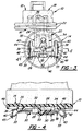
- an electrical assembly 10 of this invention comprises an electrical connector 12 and an electrical device 14 such as a sensor that is used in automotive systems.
- the electrical connector 12 and the electrical device 14 are connected to each other both mechanically and electrically without an intervening element such as a printed circuit board that is commonly used in prior art electrical assemblies of this type.
- the electrical connector 12 is configured to support the electrical device 14 and make direct mechanical and electrical connections with the supported electrical device 14. More specifically the electrical connector 12 has a one-piece connector body 16 of mouldable, thermoplastic electrically insulative material.
- the connector body 16 has an upright socket 18 at one end for receiving a mating electrical connector (not shown), and a cantilevered platform 20 at the other end for supporting the electrical device 14 in an upright position near the socket 18.
- the connector body 16 has a narrow peripheral groove defined by confronting flanges 22 that are disposed between the socket 18 and the platform 20. The narrow peripheral groove is used to mount the electrical assembly on a slotted panel wall of a protective metal casing as shown in Figure 6 of US-A-4,894,017 that is discussed in the introduction, and that is incorporated in this patent specification by reference.
- the cantilevered platform 20 has a curved rib 24 adjacent the flanges 22, a straight rib 26 at its free end and two holes 28 between the ribs for securing the electrical device 14 on the platform 20.
- the ribs 24 and 26 strengthen the platform 20 and also help locate the electrical device 14 for fastening to the platform.
- the platform 20 also has two laterally spaced bifurcated fingers 30 that project from the free end for optionally holding a second electrical device such as a diode 32 or other similar electrical device that has axial lead wires 33 extending from each end.
- the electrical connector 12 also has two one-piece terminals 34 and 35 that are insert moulded in the connector body 16.
- the insert moulded terminals 34 and 35 have exposed, upright contacts 36 at one end of generally L-shaped stampings that project into the socket 18.
- the terminals 34 and 35 have exposed contacts 38 at the other end of generally L-shaped stampings that project outwardly of the platform 20 in the lateral direction.
- the upright contacts 36 are in the from of double thickness blades that are formed by folding the one end of the stampings back over onto itself.
- the one end of the terminal 35 is bifurcated to form two upright contacts 36 at the one end.
- the contacts 38 are flanged to provide upright walls 40 that are laterally spaced from the side edges of the platform 20.
- the walls 40 are slit to provide integral straps 42 that are raised outwardly of the walls 40 to form sockets for receiving flat prongs 44 of the electrical device 14 that is mounted on the platform.
- the walls 40 also have T-shaped slots 45 for receiving the ends of the lead wires 33 of the diode 32.
- the electrical device 14 comprises a round housing 46 of thermoplastic material that has a circular lip 48 at the bottom.
- the housing also has two depending pins 50 that fit into the holes 28 when the electrical device 14 is plugged onto the platform 20.
- the electrical device 14 has two flat prongs 44 that project from the bottom of the housing 46. These flat prongs 44 are connected to electrical componentry within the housing 46 and project from the bottom of the housing 46 to connect the internal electrical componentry with external electrical devices via the electrical connector 12.
- the electrical device 14 is plugged onto the platform 20 of the electrical connector 12 so that the flat prongs 44 plug into the sockets of the contacts 38 and the plastic pins fit 50 into the holes 28.
- the plastic pins 50 are then heat staked to fasten the electrical device 14 and the electrical connector 12 together.
- another electrical device such as a diode 32 may be incorporated in the electrical assembly 10.
- This diode 32 is mechanically fastened and electrically connected to the electrical connector 12 by the lead wires 33 of the diode.
- the lead wires 33 are wedged in the bifurcated fingers 30 as shown in Figures 2, 3 and 4 to fasten the diode 32 to the front of the platform 20 while the ends of the lead wires 33 are wedged in the T-shaped slots 45 of the contacts 38 to connect the diode 32 to the electrical connector 12 electrically.
Landscapes
- Engineering & Computer Science (AREA)
- Microelectronics & Electronic Packaging (AREA)
- Connector Housings Or Holding Contact Members (AREA)
- Multi-Conductor Connections (AREA)
Applications Claiming Priority (2)
| Application Number | Priority Date | Filing Date | Title |
|---|---|---|---|
| US07/944,622 US5238429A (en) | 1992-09-14 | 1992-09-14 | Electrical assembly and connector therefor |
| US944622 | 1992-09-14 |
Publications (3)
| Publication Number | Publication Date |
|---|---|
| EP0588395A2 true EP0588395A2 (fr) | 1994-03-23 |
| EP0588395A3 EP0588395A3 (en) | 1996-01-17 |
| EP0588395B1 EP0588395B1 (fr) | 1998-11-11 |
Family
ID=25481742
Family Applications (1)
| Application Number | Title | Priority Date | Filing Date |
|---|---|---|---|
| EP93202316A Expired - Lifetime EP0588395B1 (fr) | 1992-09-14 | 1993-08-05 | Assemblage électrique et connecteur pour celui-ci |
Country Status (3)
| Country | Link |
|---|---|
| US (1) | US5238429A (fr) |
| EP (1) | EP0588395B1 (fr) |
| DE (1) | DE69322038T2 (fr) |
Cited By (2)
| Publication number | Priority date | Publication date | Assignee | Title |
|---|---|---|---|---|
| DE19648710C1 (de) * | 1996-11-25 | 1998-02-19 | Bosch Gmbh Robert | Vielpoliger Steckverbinder |
| WO2003009429A1 (fr) * | 2001-07-17 | 2003-01-30 | Robert Bosch Gmbh | Element capteur |
Families Citing this family (12)
| Publication number | Priority date | Publication date | Assignee | Title |
|---|---|---|---|---|
| JP3428717B2 (ja) * | 1994-02-07 | 2003-07-22 | 住友電装株式会社 | 電気コネクタ |
| US5668698A (en) * | 1996-01-22 | 1997-09-16 | General Motors Corporation | Smart connector for an electrical device |
| JPH10172631A (ja) * | 1996-12-04 | 1998-06-26 | Kel Corp | 電気コネクタ |
| KR100283769B1 (ko) | 1997-12-01 | 2001-03-02 | 고이데 가즈유끼 | 자동 2륜차의 배선구조 및 자동 2륜차의 배선방법 |
| US6448676B1 (en) | 1999-05-18 | 2002-09-10 | Siemens Automotive Inc. | Pulse width modulated engine cooling fan motor with integrated MOSFET |
| DE10030954A1 (de) * | 2000-06-24 | 2002-01-03 | Efen Elektrotech Fab | Stromverteiler |
| DE102004007150A1 (de) * | 2004-02-12 | 2005-08-25 | Patent-Treuhand-Gesellschaft für elektrische Glühlampen mbH | Sockel für eine Scheinwerferlampe und Scheinwerferlampe |
| US7063570B1 (en) | 2005-02-25 | 2006-06-20 | Delphi Technologies, Inc. | Electrical connector and component packaging assembly |
| WO2007113030A1 (fr) * | 2006-03-30 | 2007-10-11 | Brose Fahrzeugteile Gmbh & Co. Kg | Module de raccordement pour raccorder une unité de commande ou équivalent à une unité d'entraînement |
| US8202124B1 (en) | 2011-03-11 | 2012-06-19 | Lear Corporation | Contact and receptacle assembly for a vehicle charging inlet |
| DE102013224296A1 (de) * | 2013-11-27 | 2015-05-28 | Robert Bosch Gmbh | Elektrische Steckvorrichtung zum Anschluss einer Magnetspule und/oder eines Sensorelements |
| US20160190722A1 (en) * | 2014-12-24 | 2016-06-30 | Yazaki Corporation | Connector |
Family Cites Families (9)
| Publication number | Priority date | Publication date | Assignee | Title |
|---|---|---|---|---|
| US2976513A (en) * | 1957-01-14 | 1961-03-21 | Pennsylvania Furnace And Iron | Light unit for vehicles |
| US4430983A (en) * | 1980-12-19 | 1984-02-14 | Acf Industries, Inc. | Carburetor bleed air control solenoid improvement |
| DE3440748C2 (de) * | 1984-11-08 | 1993-12-23 | Hirschmann Richard Gmbh Co | Leitungssteckverbinder mit Bauelementeeinsatz |
| JPH055796Y2 (fr) * | 1987-02-12 | 1993-02-16 | ||
| US4871331A (en) * | 1988-05-25 | 1989-10-03 | Yazaki Corporation | Bulb socket for wedged-base bulb |
| US4956561A (en) * | 1988-12-27 | 1990-09-11 | Caterpillar Inc. | Smart power connector |
| US4894017A (en) * | 1989-01-13 | 1990-01-16 | General Motors Corporation | Electrical header assembly |
| IT219137Z2 (it) * | 1989-11-21 | 1992-12-10 | Weber Srl | Dispositivo di connessione elettrica per un iniettore di un dispositivo di alimentazione di carburante per un motore a combustione interna |
| JPH0574515A (ja) * | 1991-09-11 | 1993-03-26 | M Syst Giken:Kk | プラグ・イン型電気機器用ソケツト |
-
1992
- 1992-09-14 US US07/944,622 patent/US5238429A/en not_active Expired - Fee Related
-
1993
- 1993-08-05 EP EP93202316A patent/EP0588395B1/fr not_active Expired - Lifetime
- 1993-08-05 DE DE69322038T patent/DE69322038T2/de not_active Expired - Fee Related
Cited By (4)
| Publication number | Priority date | Publication date | Assignee | Title |
|---|---|---|---|---|
| DE19648710C1 (de) * | 1996-11-25 | 1998-02-19 | Bosch Gmbh Robert | Vielpoliger Steckverbinder |
| US5902153A (en) * | 1996-11-25 | 1999-05-11 | Robert Bosch Gmbh | Multi-pole connector having microtemperature fuse and resistor |
| EP0844701A3 (fr) * | 1996-11-25 | 1999-12-01 | Robert Bosch Gmbh | Connecteur à fiche multipolaire |
| WO2003009429A1 (fr) * | 2001-07-17 | 2003-01-30 | Robert Bosch Gmbh | Element capteur |
Also Published As
| Publication number | Publication date |
|---|---|
| DE69322038D1 (de) | 1998-12-17 |
| EP0588395A3 (en) | 1996-01-17 |
| DE69322038T2 (de) | 1999-04-01 |
| EP0588395B1 (fr) | 1998-11-11 |
| US5238429A (en) | 1993-08-24 |
Similar Documents
| Publication | Publication Date | Title |
|---|---|---|
| US6315620B1 (en) | System, method, and device for a pre-loaded straddle mounted connector assembly | |
| US5746626A (en) | Electrical connector assembly | |
| EP0588395B1 (fr) | Assemblage électrique et connecteur pour celui-ci | |
| US5876241A (en) | Horizontal battery connector | |
| US6346009B1 (en) | Shielded multiple electrical connector assembly | |
| EP2020708A1 (fr) | Module de distribution électrique et son embase | |
| CN100362704C (zh) | 具有电线控制模块的电连接器 | |
| EP0582726A1 (fr) | Douille modulaire | |
| JPH08339861A (ja) | コネクタソケット | |
| US4731925A (en) | Method for providing a power connector | |
| JPH08190903A (ja) | 印刷回路基板用の改良したバッテリーホルダ | |
| US5788520A (en) | Connector shorting bar retention | |
| US4414298A (en) | Printed circuit board mount for batteries and the like | |
| EP0709931A2 (fr) | Connecteur de bord de circuit monté en surface | |
| US5711676A (en) | Vertically mounted cable plug | |
| US6464514B1 (en) | Card edge connector with grounding pad | |
| WO2004062043A1 (fr) | Connecteur electrique de cable souple | |
| US4968266A (en) | Surface mount connector | |
| EP0948102B1 (fr) | Connecteur de bord de carte | |
| US6146212A (en) | Terminal connector assembly | |
| EP0507166A2 (fr) | Connecteur électrique de mise à la terre | |
| JP2967480B2 (ja) | 電気コネクタ | |
| US5282752A (en) | Combination connector tool | |
| US5490800A (en) | Electrical connector | |
| US6146172A (en) | Electrical connector |
Legal Events
| Date | Code | Title | Description |
|---|---|---|---|
| PUAI | Public reference made under article 153(3) epc to a published international application that has entered the european phase |
Free format text: ORIGINAL CODE: 0009012 |
|
| AK | Designated contracting states |
Kind code of ref document: A2 Designated state(s): DE FR GB IT |
|
| PUAL | Search report despatched |
Free format text: ORIGINAL CODE: 0009013 |
|
| AK | Designated contracting states |
Kind code of ref document: A3 Designated state(s): DE FR GB IT |
|
| 17P | Request for examination filed |
Effective date: 19960717 |
|
| 17Q | First examination report despatched |
Effective date: 19970116 |
|
| GRAG | Despatch of communication of intention to grant |
Free format text: ORIGINAL CODE: EPIDOS AGRA |
|
| GRAG | Despatch of communication of intention to grant |
Free format text: ORIGINAL CODE: EPIDOS AGRA |
|
| GRAH | Despatch of communication of intention to grant a patent |
Free format text: ORIGINAL CODE: EPIDOS IGRA |
|
| GRAH | Despatch of communication of intention to grant a patent |
Free format text: ORIGINAL CODE: EPIDOS IGRA |
|
| GRAA | (expected) grant |
Free format text: ORIGINAL CODE: 0009210 |
|
| AK | Designated contracting states |
Kind code of ref document: B1 Designated state(s): DE FR GB IT |
|
| REF | Corresponds to: |
Ref document number: 69322038 Country of ref document: DE Date of ref document: 19981217 |
|
| ET | Fr: translation filed | ||
| PGFP | Annual fee paid to national office [announced via postgrant information from national office to epo] |
Ref country code: FR Payment date: 19990806 Year of fee payment: 7 |
|
| PGFP | Annual fee paid to national office [announced via postgrant information from national office to epo] |
Ref country code: GB Payment date: 19990831 Year of fee payment: 7 |
|
| PLBE | No opposition filed within time limit |
Free format text: ORIGINAL CODE: 0009261 |
|
| PGFP | Annual fee paid to national office [announced via postgrant information from national office to epo] |
Ref country code: DE Payment date: 19990927 Year of fee payment: 7 |
|
| 26N | No opposition filed | ||
| PG25 | Lapsed in a contracting state [announced via postgrant information from national office to epo] |
Ref country code: GB Free format text: LAPSE BECAUSE OF NON-PAYMENT OF DUE FEES Effective date: 20000805 |
|
| GBPC | Gb: european patent ceased through non-payment of renewal fee |
Effective date: 20000805 |
|
| PG25 | Lapsed in a contracting state [announced via postgrant information from national office to epo] |
Ref country code: FR Free format text: LAPSE BECAUSE OF NON-PAYMENT OF DUE FEES Effective date: 20010430 |
|
| PG25 | Lapsed in a contracting state [announced via postgrant information from national office to epo] |
Ref country code: DE Free format text: LAPSE BECAUSE OF NON-PAYMENT OF DUE FEES Effective date: 20010501 |
|
| REG | Reference to a national code |
Ref country code: FR Ref legal event code: ST |
|
| PG25 | Lapsed in a contracting state [announced via postgrant information from national office to epo] |
Ref country code: IT Free format text: LAPSE BECAUSE OF NON-PAYMENT OF DUE FEES;WARNING: LAPSES OF ITALIAN PATENTS WITH EFFECTIVE DATE BEFORE 2007 MAY HAVE OCCURRED AT ANY TIME BEFORE 2007. THE CORRECT EFFECTIVE DATE MAY BE DIFFERENT FROM THE ONE RECORDED. Effective date: 20050805 |